EP0394169A2 - Verfahren und Gerät für die Parallelverarbeitung von Postnormalisation und Abrundung - Google Patents
Verfahren und Gerät für die Parallelverarbeitung von Postnormalisation und Abrundung Download PDFInfo
- Publication number
- EP0394169A2 EP0394169A2 EP90480045A EP90480045A EP0394169A2 EP 0394169 A2 EP0394169 A2 EP 0394169A2 EP 90480045 A EP90480045 A EP 90480045A EP 90480045 A EP90480045 A EP 90480045A EP 0394169 A2 EP0394169 A2 EP 0394169A2
- Authority
- EP
- European Patent Office
- Prior art keywords
- circuit
- rounding
- result
- floating point
- bit
- Prior art date
- Legal status (The legal status is an assumption and is not a legal conclusion. Google has not performed a legal analysis and makes no representation as to the accuracy of the status listed.)
- Withdrawn
Links
Images

Classifications
-
- G—PHYSICS
- G06—COMPUTING OR CALCULATING; COUNTING
- G06F—ELECTRIC DIGITAL DATA PROCESSING
- G06F7/00—Methods or arrangements for processing data by operating upon the order or content of the data handled
- G06F7/38—Methods or arrangements for performing computations using exclusively denominational number representation, e.g. using binary, ternary, decimal representation
- G06F7/48—Methods or arrangements for performing computations using exclusively denominational number representation, e.g. using binary, ternary, decimal representation using non-contact-making devices, e.g. tube, solid state device; using unspecified devices
- G06F7/483—Computations with numbers represented by a non-linear combination of denominational numbers, e.g. rational numbers, logarithmic number system or floating-point numbers
-
- G—PHYSICS
- G06—COMPUTING OR CALCULATING; COUNTING
- G06F—ELECTRIC DIGITAL DATA PROCESSING
- G06F7/00—Methods or arrangements for processing data by operating upon the order or content of the data handled
- G06F7/38—Methods or arrangements for performing computations using exclusively denominational number representation, e.g. using binary, ternary, decimal representation
- G06F7/48—Methods or arrangements for performing computations using exclusively denominational number representation, e.g. using binary, ternary, decimal representation using non-contact-making devices, e.g. tube, solid state device; using unspecified devices
- G06F7/499—Denomination or exception handling, e.g. rounding or overflow
- G06F7/49936—Normalisation mentioned as feature only
-
- G—PHYSICS
- G06—COMPUTING OR CALCULATING; COUNTING
- G06F—ELECTRIC DIGITAL DATA PROCESSING
- G06F7/00—Methods or arrangements for processing data by operating upon the order or content of the data handled
- G06F7/38—Methods or arrangements for performing computations using exclusively denominational number representation, e.g. using binary, ternary, decimal representation
- G06F7/48—Methods or arrangements for performing computations using exclusively denominational number representation, e.g. using binary, ternary, decimal representation using non-contact-making devices, e.g. tube, solid state device; using unspecified devices
- G06F7/499—Denomination or exception handling, e.g. rounding or overflow
- G06F7/49942—Significance control
- G06F7/49947—Rounding
- G06F7/49957—Implementation of IEEE-754 Standard
Definitions
- the present invention relates to a method and apparatus for performing floating point arithmetic operations in a data processing system. More particularly, the invention relates to an apparatus, and method for implementing the apparatus, for performing floating point operations by parallel processing the steps of normalizing and rounding to complete the floating point operation. These steps are performed after the floating point arithmetic operation has been completed, and a floating point answer has been developed.
- the typical floating point arithmetic operation may be accomplished in either single precision or double precision format.
- Each of these formats utilizes a sign, exponent and fraction field, where the respective fields occupy predefined portions of the floating point number.
- the sign field is a single bit occupying the most significant bit position;
- the exponent field is an 8-bit quantity occupying the next-most significant bit positions;
- the fraction field occupies the least significant 23-bit positions.
- the sign field is a single bit occupying the most significant bit position;
- the exponent field is an 11-bit field occupying the next-most significant bit positions;
- the frac tion field is a 52-bit field occupying the least significant bit positions.
- indicator bits are injected into the fraction field of the floating point number, and are used by the arithmetic control logic to indicate when certain conditions exist in the floating point operation. For example, an "implicit" bit I is created by the arithmetic control logic when the exponent of the floating point number has a nonzero value. The implicit bit I is created at the time a floating point number is loaded into the arithmetic registers, and the implicit bit I occupies the first bit position in the fraction field of the number.
- a "guard" bit G is set by the floating point control logic during certain arithmetic operations, as an indicator of the loss of precision of the floating point number being processed.
- the G bit is set when a right shift, required for normalization, shifts a significant bit off the right side of the register capacity. For single precision numbers the G bit occupies bit position 25 in the fraction field; for double precision numbers the G bit occupies position 54 in the fraction field.
- a "round” bit is similarly used for certain floating point arithmetic operations, and is set by the arithmetic control logic, and the R bit occupies bit position 26 in the fraction field of a single precision number, and bit position 55 in the fraction field of a double precision number.
- a "sticky" bit S is an indicator bit which is set in certain floating point arithmetic operations when any lower precision bit is a "1", as an indicator that the floating point number has lost some precision.
- the S bit occupies position 27 of the fraction field in a single precision floating point number, and position 56 in the fraction field of a double precision floating point number.
- the three extra bits in the fraction field are used exclusively for rounding operations, after the result has been normalized.
- the guard (G) and round (R) bits are treated as if they are a part of the fraction; they are shifted with the rest of the fraction, and included in all arithmetic.
- the sticky (S) bit is not shifted with the fraction, but is included in the arithmetic. It acts as a "catcher" for 1's shifted off the right of the fraction; when a 1 is shifted off the right side of the fraction, the S bit will remain a 1 until normalization and rounding are finished.
- the “round to nearest” mode means that the value nearest to the infinitely precise result should be delivered. If the two nearest representable values are equally near, the one with its least significant bit zero shall be delivered.
- the “round to positive infinity” mode means that the value closest to and not less than the infinitely precise result should be delivered.
- the “round to negative infinity” mode means that the value closest to and not greater than the infinitely precise result should be delivered.
- the “round to zero” mode means that the result delivered should be the closest to but not greater in magnitude than the infinitely precise result. If none of the G, R, and S bits are a "1", no rounding will be accomplished regardless of the mode of rounding selected.
- the invention includes an apparatus for performing floating point arithmetic operations, and a method for processing the apparatus to implement parallel normalization and rounding operations.
- the fractional result of a floating point arithmetic operation is examined at the first 2-bit positions; if these 2-bit positions are in the form 1.X no normalization will be required and only a rounding opera tion will be executed. If the first 2-bit positions are in the form 0.1X the fraction will be shifted left one position and then the rounding operation will be implemented, without further normalization. If the first 2-bits are in neither of the predescribed formats the fraction will be normalized and sent directly to an output without the necessity of incurring a rounding operation. Since the need to perform normalization and/or rounding is completely predictable and dependent upon the foregoing 2-bit formats, the operation of normalization and rounding can be accomplished as a parallel processing operation rather than as a sequential processing operation.
- FIG. 1 there is shown a block diagram of the floating point arithmetic circuit 10 which is used in conjunction with the present invention.
- the execution of floating point arithmetic utilizes this circuit because of the specific algorithms which must be performed to determine the proper results.
- This circuit presumes that the floating point numbers have been prearranged according to a particular format, where the most significant bit represents the sign of the floating point number, and wherein a group of the next-most significant bits represent the exponent of the floating point number, and wherein the remaining bits represent the fraction value of the number; i.e., the fraction value presuming that the binary point is placed at the left-most end of the fraction value.
- the hardware registers and logic associated with FIG. 1 include four additional bits; the I bit occupies the most significant position in the fraction field, and the G, R and S bits respectively occupy the least significant bit positions in the fraction field.
- Floating point operands cannot be added to or subtracted from each other unless their exponents are equal. This requires that their exponents be compared, and the operand fraction with the smaller exponent be shifted the amount of the exponent difference. The fractions can then be added or subtracted with the larger exponent as the result exponent. Multiplication of floating point operands requires that the exponents be added and the fractions multiplied. Division of floating point operands requires that the divisor exponent be subtracted from the dividend exponent and the dividend fraction be divided by the divisor fraction.
- the floating point arithmetic circuit of FIG. 1 can support both single and double precision arithmetic opera tions. It is designed to support a floating point add or subtract operation, a 14-bit floating point multiply operation, and a 2-bit floating point divide operation.
- the floating point arithmetic circuit 10 of FIG. 1 utilizivelyes a storage data bus 12 for receiving and transmitting data from other sources, such as a data processing system or the like.
- Information received over data storage bus 12 may be transmitted into a plurality of floating point registers 14.
- floating point registers 14 In the preferred embodiment there are eight floating point registers 14, each adapted to hold the floating point operands and the results of floating point operations.
- Floating point registers 14 may transmit information to an FA register 16, an FB register 18, or an FC register 22.
- FA register 16 may also transmit information back to floating point registers 14.
- the FA register 16 is a destination register for data from the floating point registers 14, and is the source register for data being transmitted to the floating point registers 14.
- the FA register 16 is also the source register for data which may be transferred to a memory via storage data bus 12, and it is a destination register for data transmitted from the carry-propagate adder 30, the exponent adder 20, and from the normalize-round circuit 34.
- the FA register 16 has outputs to the multiple selector 24, the prealigner circuit 26, the normalize-round circuit 34, and the exponent adder 20.
- the FA register 16 contains the second operand for add, subtract, compare, multiply and divide operations.
- FA register 16 has a section 16a for holding the exponent of the floating point number, and a section 16b for holding the operand portion of the floating point number.
- the FA register 16 In order to selectively control which of the plurality of inputs to the FA register 16 are to be gated into the register, the FA register 16 has an input multiplexer circuit 15 associated therewith. Multiplexer circuit 15 provides for the selective gating of the various inputs into register 16, under control of an activation signal A. Other registers in the floating point arithmetic circuit 10 have similar multiplexer input controls.
- a control logic circuit 11 generates all of the activation signals required for data interchange and processing operations within floating point arithmetic circuit 10.
- Control logic circuit 11 has a plurality of control signal outputs, designated A, each of which serve as control inputs to various circuits and registers. It is well within the skill of the art to understand the need and design for a control logic circuit 11, as well as the activation signals A which are required for the operation of floating point arithmetic circuit 10; accordingly, a detailed presentation of these circuits and signals is not required herein.
- the FB register 18 is a destination register for data received from the storage data buss 12, the floating point registers 14, and is also a destination register for data from the carry-propagate adder 30, and from the normalize-round circuit 34. It has outputs to the multiple selector 24, the prealigner circuit 26, and the exponent adder 20.
- the FB register is used to contain the first operand for the add, subtract, compare and divide operations; it also contains the intermediate result of the add, subtract and multiply operations.
- the FB register 18 has a section 18a for containing the exponent value of the floating point number, and a section 18b for containing the operand portion of the floating point number, and has an input multiplexer circuit 17 for gating data into the register under control of activation signals from control logic circuit 11.
- the FC register 22 is a destination register for data from memory via storage data buss 12, and a destination register for data from the carry-propagate adder 30 and from the normalize-round circuit 34. It is also the destination register from the floating point registers 14.
- the FC register 22 has outputs to the multiple selector 24, the prealigner circuit 26, and the normalize-round circuit 34.
- the FC register 22 is used to contain the first operand of the multiply operation, and it is the destination register for the result of a divide operation.
- An input multiplexer circuit 21 controls the gating of data into FC register 22, under control of activation signals from control logic circuit 11.
- the exponent adder 20 is a 13-bit adder circuit that is used for exponent arithmetic. It handles the exponent calculations for either single or double precision exponents.
- the exponent adder is a source for data transmitted. to FA register section 16a, and FB register section 18a.
- the exponent adder 20 has an input multiplexer circuit 19.
- the prealigner circuit 26 is used to pre-shift the fraction with the smaller exponent for the add and subtract operation, which is necessary to make the floating point operand exponents equal prior to an add or subtract operation.
- the prealigner circuit 26 has the capability to shift a floating point fraction right from 0 to 55-bit positions, depending upon whether single or double precision arithmetic is being performed.
- the prealigner circuit 26 has an output to the carry-propagate adder 30, and to the FC register 22.
- the multiple selector 24 is a logic circuit which generates multiples of the multiplicand for the multiply operation, and multiples of the divisor for the divide operation. For the divide operation, the multiples are decoded from the high-order bits of the dividend, or partial dividend, and of the divisor. The complement of the operand may be generated by the multiple selector when necessary.
- the multiple selector 24 receives data from the FA register 16, the FB register 18, and the FC register 22. The multiple selector 24 has outputs to the carry-save adder tree 28.
- the carry-save adder tree 28 will permit three operands to be added together at the same time. This permits the use of a divide algorithm which generates two quotient bits per iteration.
- the carry-save adder tree 28 receives data from the multiple selector 24, and transmits data to the carry-propagate adder 30.
- the carry-propagate adder 30 is a 57-bit adder, and has an input from the carry-save adder 28 for generating the partial product of a multiply operation or the partial dividend of a divide operation.
- the carry- propagate adder circuit 30 may also receive inputs from the prealigner circuit 26, the FA register 16, and the FB register 18.
- the carry-propagate adder has an output connection to the FA register 16 and the FB register 18.
- An input multiplexer circuit 29 controls the gating of data into carry-propagate adder 30, under control of activation signals A from control logic circuit 11.
- the normalize-round circuit 34 includes a normalize circuit 34a which is used to normalize the results of a floating point operation. For example, the result of a multiply operation may require a left-shift of 1-bit in order to normalize the fraction, and the result of an add or subtract operation may require a left-shift of up to 54-bit positions.
- the normalize-round circuit 34 also includes a round circuit 34b, which contains an incrementor circuit, for use in certain rounding operations, where the result may have to be incremented by a value of 1 in the low-order bit position.
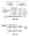
- FIG. 2 shows the parts of the circuit of FIG. 1 which are utilized for normalization and rounding after an arithmetic operation has been completed according to the teachings of the prior art.
- FIG. 3 shows a data flow path for prior art normalizing and rounding, wherein the floating point result needing normalization and rounding is first processed for normalization, and subsequently processed for rounding. The steps of the data flow path are under control of a normalize and rounding control logic circuit 11, and the operations are sequentially performed. Referring to the block diagram of FIG. 2, the sequence of normalizing and rounding requires several steps of operation. First, the result fraction held in register 16 is normalized by gating it into a normalize logic circuit 34a, which is essentially a shifter.
- the data in normalize circuit 34a is left shifted to eliminate all of the leading zeros, and a count is made of the number of shifts required to accomplish this.
- the shift count is subtracted from the result exponent of register 16, in exponent adder 20, and the resulting exponent is replaced into register 16a.
- the normalized fraction is rounded by round circuit 34b, which operates according to predetermined rounding parameters, and the rounded fraction is replaced into register 16b.
- the new exponent and fraction quantity is transferred into one of the floating point registers 14 for subsequent operations.
- the present invention provides a solution to this time problem, by converting the sequential normalizing and rounding operations into parallel operations.
- the result fraction for all arithmetic operations can be represented in one of the four following formats :
- any multiplication operation utilizing pre-normalized operands will result in a product in either the form of case 1 or case 2 above.
- any division operation which is performed using a 2-bit non-restore divide algorithm, which uses pre-normalized operands will produce a quotient always in the form of case 1 or case 2 above.
- Addition and subtraction operations will provide results in any of the four possible formats.
- the present invention deals with the formats represented by cases 1, 2 and 3 above, and copending U.S. patent application serial no. 07/339,347 (Docket RO 9 89 004), entitled "Floating Point Normalization and Rounding Prediction Circuit, filed of even date herewith, discloses an invention that effectively converts case 4 into a case 1 format.
- Table 1 shows a chart which illustrates examples for addition solutions and Table 2 illustrates examples for subtraction solutions.
- operand 1 and 2 are the fractional values to be added or subtracted, and the "exponent difference” indicates if the operand exponents are equal (difference of zero) or not equal (difference greater than zero), or have a difference of one.
- the "result” column identifies the possible formats of the answer.
- the column entitled “Norm” indicates whether normalization is needed (Y), and the column entitled “Round” indicates whether rounding is needed, and if so, how the rounding will be performed.
- R1 indicates that the method of the copending application hereinbefore identified will be used for rounding
- R2 indicates that a round will occur without any shifting operation
- R3 indicates that a 1-bit shift to the left will occur before rounding.
- the fractional result is shifted 1-bit position to the right and rounded when needed.
- the fractional result is shifted 1-bit position to the left and rounding is done normally.
- the result When subtracting two normalized numbers with the same exponent, the result will be either 0.1XXX... or 0.0XXX... . For both results, the guard (G), round (R) and sticky (S) will not be set, so normalization is the only operation which needs to be completed. If one exponent is higher, the result will be in the format 1.XXX... or 0.1XXX or 0.0XXX. In the first format (1.XXX%) rounding is the only operation needed, and in the second format (0.1XXX%) the result can be normalized and rounded through a single one-bit left shift and then rounded normally. In the third format a normalize only operation is required. This third format can only occur for a difference of 1 between the two exponents.
- the result will be of the form 0.1X or 1.XX. If the difference between the exponents is 1, then only the guard bit G can be set; the guard bit G will be cleared upon normalization since the result is 0.0X; i.e., no requirement for rounding will exist with the third format. In other words, it is never necessary to both shift more than 1-bit and also to round the result.
- the possible results are in the format 1.XXX... and 0.1XXX.... This case may cause the rounding bits to be set, and the result may be rounded without and with the 1-bit left shift respectively. In other words, it is apparent that the result from a subtraction between a normalized operand and denormalized operand never require more than a 1-bit shift when rounding is required.
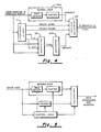
- FIG. 4 shows the arithmetic circuit 10 modification organization for normalization and rounding in parallel according to the teachings of the present invention.
- the fraction resulting from an arithmetic operation is held in register 16 in one of the three possible formats described above.
- the fraction result is simultaneously coupled to normalize circuit 34a and selector circuit 53.
- Normalize circuit 34a operates in the conventional manner described hereinbefore, and provides a normalized output to output selector circuit 56.
- the parallel connection from register 16 to selector circuit 53 is further controlled by control logic circuit 11.
- Control logic circuit 11 examines the first two bits of the fractional result, and activates the selector line (1.X) if the 2-bit format is 1.X, and activates the selector line (0.1X) if the 2-bit format is 0.1X. If the 2-bit format is neither 1.X nor 0.1X the fractional result from register 16 is not passed through selector circuit 53 to round circuit 34b, but is sen t to normalizer 34a. If the fractional result 2-bit format is 1.X, the fractional result is passed directly through selector circuit 53 into rounder circuit 34b, and thence to output selector circuit 56; the signal "select round” is simultaneously activated, causing output selector circuit 56 to gate the signals received from rounder circuit 34 back to register 16. This sequence is followed because, when the 2-bit format is 1.X, the implicit bit I is set to a "1," and no normalization is required the only operation being required is rounding.
- the control logic circuit 11 activates signal line (0.1X) thereby shifting the fractional result one bit position to the left while at the same time transferring the result through selector circuit 53 into rounder 34b, and thence into output selector 56.
- Control logic circuit 11 will activate either the signal "select norm” or the signal “select round” depending upon the 2-bit format examination, and also depending upon the value of the exponent difference.
- the various combinations which are possible, and which determine the signal line to be activated, are shown in Tables 1 and 2. It is apparent from an examination of Tables 1 and 2 that activation of either the "select norm” signal or the “select round” signal, but not both, will accomplish the desired result in all cases. It is therefore apparent that, according to the teachings of the invention, the postnormalization and rounding operations may be performed in parallel as described, obviating the need for sequential processing as was accomplished in the prior art. This parallel processing reduces the total time required for such post-processing, and consequently results in a net savings in processing time in accordance with the present invention.
- FIG. 5 shows the data flow path for practice of the invention, wherein the fraction result is simultaneously cou pled to both the normalizer and the rounder, and the parallel processing is controlled by the control logic 11.
- Control logic 11 signals to the output selector 56 to indicate which of the two parallel paths contain the correct output result.
Landscapes
- Engineering & Computer Science (AREA)
- General Physics & Mathematics (AREA)
- Physics & Mathematics (AREA)
- Mathematical Optimization (AREA)
- Computing Systems (AREA)
- Mathematical Analysis (AREA)
- Computational Mathematics (AREA)
- Pure & Applied Mathematics (AREA)
- Theoretical Computer Science (AREA)
- Nonlinear Science (AREA)
- General Engineering & Computer Science (AREA)
- Complex Calculations (AREA)
- Image Processing (AREA)
Applications Claiming Priority (2)
| Application Number | Priority Date | Filing Date | Title |
|---|---|---|---|
| US07/339,348 US4926370A (en) | 1989-04-17 | 1989-04-17 | Method and apparatus for processing postnormalization and rounding in parallel |
| US339348 | 1989-04-17 |
Publications (2)
| Publication Number | Publication Date |
|---|---|
| EP0394169A2 true EP0394169A2 (de) | 1990-10-24 |
| EP0394169A3 EP0394169A3 (de) | 1992-06-24 |
Family
ID=23328606
Family Applications (1)
| Application Number | Title | Priority Date | Filing Date |
|---|---|---|---|
| EP19900480045 Withdrawn EP0394169A3 (de) | 1989-04-17 | 1990-03-13 | Verfahren und Gerät für die Parallelverarbeitung von Postnormalisation und Abrundung |
Country Status (3)
| Country | Link |
|---|---|
| US (1) | US4926370A (de) |
| EP (1) | EP0394169A3 (de) |
| JP (1) | JPH02294820A (de) |
Cited By (3)
| Publication number | Priority date | Publication date | Assignee | Title |
|---|---|---|---|---|
| EP0560945A4 (en) * | 1990-12-03 | 1995-07-12 | Univ Leland Stanford Junior | Adaptive decision feedback equalizer apparatus for processing information stored on digital storage media |
| WO1998006029A1 (en) * | 1996-08-07 | 1998-02-12 | Valery Yakovlevich Gorshtein | Apparatus and methods for execution of computer instructions |
| US5844830A (en) * | 1996-08-07 | 1998-12-01 | Sun Microsystems, Inc. | Executing computer instrucrions by circuits having different latencies |
Families Citing this family (26)
| Publication number | Priority date | Publication date | Assignee | Title |
|---|---|---|---|---|
| CA1309665C (en) * | 1987-06-27 | 1992-11-03 | Kenzo Akagiri | Amplitude compressing/expanding circuit |
| EP0472148B1 (de) * | 1990-08-24 | 2001-05-09 | Matsushita Electric Industrial Co., Ltd. | Verfahren und Gerät zur Berechnung von Gleitkommadaten |
| US5150319A (en) * | 1991-05-03 | 1992-09-22 | Sun Microsystems, Inc. | Circuitry for rounding in a floating point multiplier |
| US5258943A (en) * | 1991-12-23 | 1993-11-02 | Intel Corporation | Apparatus and method for rounding operands |
| US5822557A (en) * | 1991-12-27 | 1998-10-13 | Fujitsu Limited | Pipelined data processing device having improved hardware control over an arithmetic operations unit |
| US5390134A (en) * | 1993-01-29 | 1995-02-14 | Hewlett-Packard Company | System and method for reducing latency in a floating point processor |
| KR0139733B1 (ko) * | 1994-04-29 | 1998-07-01 | 구자홍 | 부동 소수점 덧셈/뺄셈 연산기의 반올림 방법 및 장치 |
| US5548544A (en) * | 1994-10-14 | 1996-08-20 | Ibm Corporation | Method and apparatus for rounding the result of an arithmetic operation |
| US5550768A (en) * | 1995-01-31 | 1996-08-27 | International Business Machines Corporation | Rounding normalizer for floating point arithmetic operations |
| US5757682A (en) * | 1995-03-31 | 1998-05-26 | International Business Machines Corporation | Parallel calculation of exponent and sticky bit during normalization |
| US5808926A (en) * | 1995-06-01 | 1998-09-15 | Sun Microsystems, Inc. | Floating point addition methods and apparatus |
| US5635858A (en) * | 1995-06-07 | 1997-06-03 | International Business Machines, Corporation | Zero-stopping incrementers |
| US5886915A (en) * | 1995-11-13 | 1999-03-23 | Intel Corporation | Method and apparatus for trading performance for precision when processing denormal numbers in a computer system |
| US5880983A (en) * | 1996-03-25 | 1999-03-09 | International Business Machines Corporation | Floating point split multiply/add system which has infinite precision |
| US5764549A (en) * | 1996-04-29 | 1998-06-09 | International Business Machines Corporation | Fast floating point result alignment apparatus |
| US5790445A (en) * | 1996-04-30 | 1998-08-04 | International Business Machines Corporation | Method and system for performing a high speed floating point add operation |
| US6167419A (en) * | 1997-04-01 | 2000-12-26 | Matsushita Electric Industrial Co., Ltd. | Multiplication method and multiplication circuit |
| US6151615A (en) * | 1997-09-02 | 2000-11-21 | Intrinsity, Inc. | Method and apparatus for formatting an intermediate result for parallel normalization and rounding technique for floating point arithmetic operations |
| US6185593B1 (en) | 1997-09-02 | 2001-02-06 | Intrinsity, Inc. | Method and apparatus for parallel normalization and rounding technique for floating point arithmetic operations |
| US6173299B1 (en) | 1997-09-02 | 2001-01-09 | Intrinsity, Inc. | Method and apparatus for selecting an intermediate result for parallel normalization and rounding technique for floating point arithmetic operations |
| US6175847B1 (en) | 1998-07-22 | 2001-01-16 | Intrinsity, Inc. | Shifting for parallel normalization and rounding technique for floating point arithmetic operations |
| US6684232B1 (en) * | 2000-10-26 | 2004-01-27 | International Business Machines Corporation | Method and predictor for streamlining execution of convert-to-integer operations |
| KR100574144B1 (ko) * | 2001-01-31 | 2006-04-25 | 마츠시타 덴끼 산교 가부시키가이샤 | 복호 장치, 기지국 장치, 통신 단말 장치 및 복호 방법 |
| US10540143B2 (en) | 2015-10-24 | 2020-01-21 | Alan A. Jorgensen | Apparatus for calculating and retaining a bound on error during floating point operations and methods thereof |
| US9817662B2 (en) | 2015-10-24 | 2017-11-14 | Alan A Jorgensen | Apparatus for calculating and retaining a bound on error during floating point operations and methods thereof |
| US12124936B2 (en) * | 2020-10-12 | 2024-10-22 | Black Sesame Technologies Inc. | Integer-based fused convolutional layer in a convolutional neural network |
Family Cites Families (14)
| Publication number | Priority date | Publication date | Assignee | Title |
|---|---|---|---|---|
| US4528640A (en) * | 1982-07-13 | 1985-07-09 | Sperry Corporation | Method and a means for checking normalizing operations in a computer device |
| JPS5983244A (ja) * | 1982-11-04 | 1984-05-14 | Nec Corp | 演算処理装置 |
| JPS608933A (ja) * | 1983-06-28 | 1985-01-17 | Nec Corp | 演算処理装置 |
| US4562553A (en) * | 1984-03-19 | 1985-12-31 | Analogic Corporation | Floating point arithmetic system and method with rounding anticipation |
| JPS6125245A (ja) * | 1984-07-12 | 1986-02-04 | Nec Corp | 丸め処理回路 |
| JPS61122750A (ja) * | 1984-11-20 | 1986-06-10 | Matsushita Electric Ind Co Ltd | 演算装置 |
| JPS61131123A (ja) * | 1984-11-30 | 1986-06-18 | Toshiba Corp | 浮動小数点演算装置 |
| JPH0644225B2 (ja) * | 1986-03-27 | 1994-06-08 | 日本電気株式会社 | 浮動小数点丸め正規化回路 |
| US4758972A (en) * | 1986-06-02 | 1988-07-19 | Raytheon Company | Precision rounding in a floating point arithmetic unit |
| JP2558669B2 (ja) * | 1986-12-29 | 1996-11-27 | 松下電器産業株式会社 | 浮動小数点演算装置 |
| JP2537876B2 (ja) * | 1987-06-11 | 1996-09-25 | 松下電器産業株式会社 | 丸め処理回路 |
| JP2555135B2 (ja) * | 1988-03-11 | 1996-11-20 | 富士通株式会社 | 演算回路 |
| JPH0776911B2 (ja) * | 1988-03-23 | 1995-08-16 | 松下電器産業株式会社 | 浮動小数点演算装置 |
| JPH02115926A (ja) * | 1988-10-26 | 1990-04-27 | Matsushita Electric Ind Co Ltd | 浮動小数点正規化丸め装装置 |
-
1989
- 1989-04-17 US US07/339,348 patent/US4926370A/en not_active Expired - Fee Related
-
1990
- 1990-03-13 EP EP19900480045 patent/EP0394169A3/de not_active Withdrawn
- 1990-04-17 JP JP2099453A patent/JPH02294820A/ja active Pending
Cited By (5)
| Publication number | Priority date | Publication date | Assignee | Title |
|---|---|---|---|---|
| EP0560945A4 (en) * | 1990-12-03 | 1995-07-12 | Univ Leland Stanford Junior | Adaptive decision feedback equalizer apparatus for processing information stored on digital storage media |
| WO1998006029A1 (en) * | 1996-08-07 | 1998-02-12 | Valery Yakovlevich Gorshtein | Apparatus and methods for execution of computer instructions |
| US5844830A (en) * | 1996-08-07 | 1998-12-01 | Sun Microsystems, Inc. | Executing computer instrucrions by circuits having different latencies |
| US5963461A (en) * | 1996-08-07 | 1999-10-05 | Sun Microsystems, Inc. | Multiplication apparatus and methods which generate a shift amount by which the product of the significands is shifted for normalization or denormalization |
| US6099158A (en) * | 1996-08-07 | 2000-08-08 | Sun Microsystems, Inc. | Apparatus and methods for execution of computer instructions |
Also Published As
| Publication number | Publication date |
|---|---|
| EP0394169A3 (de) | 1992-06-24 |
| JPH02294820A (ja) | 1990-12-05 |
| US4926370A (en) | 1990-05-15 |
Similar Documents
| Publication | Publication Date | Title |
|---|---|---|
| EP0394169A2 (de) | Verfahren und Gerät für die Parallelverarbeitung von Postnormalisation und Abrundung | |
| US4941120A (en) | Floating point normalization and rounding prediction circuit | |
| US6529928B1 (en) | Floating-point adder performing floating-point and integer operations | |
| US5357237A (en) | In a data processor a method and apparatus for performing a floating-point comparison operation | |
| EP0973089B1 (de) | Verfahren und Gerät zur Berechnung von Gleitkommadaten | |
| US5373461A (en) | Data processor a method and apparatus for performing postnormalization in a floating-point execution unit | |
| US4758972A (en) | Precision rounding in a floating point arithmetic unit | |
| US5128889A (en) | Floating-point arithmetic apparatus with compensation for mantissa truncation | |
| US6751644B1 (en) | Method and apparatus for elimination of inherent carries | |
| EP0483864A2 (de) | Hardware-Anordnung zur Addition und Subtraktion von Gleitkommazahlen | |
| US5548545A (en) | Floating point exception prediction for compound operations and variable precision using an intermediate exponent bus | |
| US5247471A (en) | Radix aligner for floating point addition and subtraction | |
| US5260889A (en) | Computation of sticky-bit in parallel with partial products in a floating point multiplier unit | |
| EP0394161A2 (de) | Die Wahl von Divisormultiplizierern in einer Gleitkomma-Divisionsschaltung | |
| EP0394162A2 (de) | Zweibit-Gleitkomma-Divisionsschaltung mit nur einem Übertragsicherstellungsaddierer | |
| USH1222H (en) | Apparatus for determining sticky bit value in arithmetic operations | |
| US5117384A (en) | Method and apparatus for exponent adder | |
| EP0512686B1 (de) | Abrundungsschaltung in einem Gleitkommamultiplizierer | |
| US4979141A (en) | Technique for providing a sign/magnitude subtraction operation in a floating point computation unit | |
| EP0332215B1 (de) | Operationsschaltung für auf die Fliesskommadarstellung basierenden Operanden | |
| US20070038693A1 (en) | Method and Processor for Performing a Floating-Point Instruction Within a Processor | |
| US5432727A (en) | Apparatus for computing a sticky bit for a floating point arithmetic unit | |
| US5570309A (en) | Iterative arithmetic processor | |
| US6185593B1 (en) | Method and apparatus for parallel normalization and rounding technique for floating point arithmetic operations | |
| EP0438962A2 (de) | Verfahren und Gerät zur Addition von Exponenten |
Legal Events
| Date | Code | Title | Description |
|---|---|---|---|
| PUAI | Public reference made under article 153(3) epc to a published international application that has entered the european phase |
Free format text: ORIGINAL CODE: 0009012 |
|
| AK | Designated contracting states |
Kind code of ref document: A2 Designated state(s): DE FR GB |
|
| 17P | Request for examination filed |
Effective date: 19901213 |
|
| PUAL | Search report despatched |
Free format text: ORIGINAL CODE: 0009013 |
|
| AK | Designated contracting states |
Kind code of ref document: A3 Designated state(s): DE FR GB |
|
| 17Q | First examination report despatched |
Effective date: 19940928 |
|
| STAA | Information on the status of an ep patent application or granted ep patent |
Free format text: STATUS: THE APPLICATION IS DEEMED TO BE WITHDRAWN |
|
| 18D | Application deemed to be withdrawn |
Effective date: 19960206 |