EP0393309B1 - Multiple depth buffers for graphics and solid modelling - Google Patents
Multiple depth buffers for graphics and solid modelling Download PDFInfo
- Publication number
- EP0393309B1 EP0393309B1 EP90100993A EP90100993A EP0393309B1 EP 0393309 B1 EP0393309 B1 EP 0393309B1 EP 90100993 A EP90100993 A EP 90100993A EP 90100993 A EP90100993 A EP 90100993A EP 0393309 B1 EP0393309 B1 EP 0393309B1
- Authority
- EP
- European Patent Office
- Prior art keywords
- buffer means
- depth
- intensity
- solid
- depths
- Prior art date
- Legal status (The legal status is an assumption and is not a legal conclusion. Google has not performed a legal analysis and makes no representation as to the accuracy of the status listed.)
- Expired - Lifetime
Links
Images


Classifications
-
- G—PHYSICS
- G06—COMPUTING; CALCULATING OR COUNTING
- G06T—IMAGE DATA PROCESSING OR GENERATION, IN GENERAL
- G06T15/00—3D [Three Dimensional] image rendering
- G06T15/10—Geometric effects
- G06T15/40—Hidden part removal
- G06T15/405—Hidden part removal using Z-buffer
Definitions
- This invention relates generally to computer graphics and solid model generation and, in particular, to apparatus and method for generating realistically shaded pictures or images of solids defined in Constructive Solid Geometry (CSG) as Boolean combinations of simple primitive volumes.
- CSG Constructive Solid Geometry
- Solid Modelling systems play an increasingly important role in the design of manufactured parts and of manufacturing processes. These systems provide users with both interactive design tools which considerably reduce the cost of design activity and also with simulation and analysis tools which shorten the design cycle and improve the quality of the final products and the efficiency of manufacturing processes.
- a solid can be described in terms of its boundary as a list of the types, positions, and dimensions of all of the solids' faces. However, such a description is in general too "verbose" for humans, who prefer to design solids in a hierarchical and incremental manner by combining or altering previously defined subsolids. Many such combinations of subsolids are precisely specified through Boolean set theoretic operations. For example, assembling two parts into a single solid can be modelled mathematically as a set theoretic union. Further shape modifications that produce specific geometric features, such as slots, holes and bosses, are often formulated in terms of set theoretic unions and differences between the solid to be modified and simple primitive volumes, such as cylinders or blocks, to be added to or subtracted from the solid.
- a solid model is often employed to represent and analyze the geometric effects of certain manufacturing operations such as material removal by milling and drilling. Such geometric effects can also be expressed in terms of set theoretic operators as, for example, the difference between a part and a region swept by a cutter. Applying a sequence of such operations is an effective method of simulating a machining process. Given the trajectory of a cutter, a solid modeller can be used to verify that the cutter does not collide with fixtures, and also to compute how much material is removed during each motion of the cutter. Such an analysis is important for planning efficient and error free manufacturing processes. The analysis requires the ability to compute Boolean set intersections between solids and to check whether such an intersection is empty or not.
- the probability of being able to assemble several parts can be analyzed with a solid modeller by producing a large number of models of each part to be assembled, according to specified form and position tolerances, and then determining in which cases the models interfere.
- two solids are considered to interfere if and only if their set theoretic intersection is a non-empty three dimensional set.
- a solid model which can represent parts, tools or characterize the effect of manufacturing operations, can be specified by combining subsolids or primitive volumes through set theoretic Boolean operations such as the union, intersection, and difference of sets.
- Such a solid is represented by a set theoretic Boolean expression which can be efficiently stored within a computer memory in a binary tree representation.
- Such a solid modelling technique is for example disclosed in COMPUTER & GRAPHICS, vol. 10, no. 4, 1986, pages 333-339, Pergamons Journals Ltd, Oxford, GB; M. GERVAUTZ: "Three improvements of the ray tracing algorithm for CGS trees".
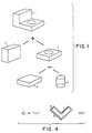
- Solid 1 is an illustrative binary tree representation of a solid (1) which is composed of the union of two subsolids (2) and (3).
- Subsolid (3) is composed of the difference between the block primitive (4) and the cylindrical primitive (5).
- the form of such a tree is directly obtained by parsing the Boolean expression (2) + ((4)-(5)).
- the root of the tree (solid 1) is associated with the solid defined by the Boolean expression.
- Internal nodes of the tree correspond to Boolean operations and are associated with subsolids.
- Leaves of the tree are associated with primitive volumes, which often are the intersection of relatively simple algebraic half-spaces, that is, regions of space where a simple polynomial function of three space coordinates has a non-positive value.
- a ball of radius R centered at the origin is a half-space defined by the function x2 + y2 + z2 - R2 ⁇ 0.
- An arbitrarily positioned and oriented primitive volume can be described in terms of a rigid motion transformation, a combination of a rotation with a translation, and of a congruent primitive volume defined in a convenient local coordinate system.
- Simple primitive volumes can be represented by their type, such as sphere, cylinder or cone, and by a relatively few intrinsic parameters such as radius, length and apex angle. Such a tree is known as a Constructive Solid Geometry representation, and will be abbreviated hereinafter as CSG.
- the positions and dimensions, or intrinsic parameters, of the primitive volumes may be expressed in terms of a few primary parameters which characterize a particular member in an entire family of solids represented by the CSG tree.
- the resulting parameterized CSG representation can therefore be conveniently used to model, for example, an assembly of parts whose dimensions vary within tolerance limits and thus be employed to model and solve the problems described earlier.
- assembly analysis and simulation of manufacturing processes are based on repetitive detection of solid interferences, which involves testing as to whether an intersection of two solids corresponds to an empty set, and also of differences between solids, which involves testing as to whether a symmetric difference of two solids corresponds to an empty set.
- solid interferences which involves testing as to whether an intersection of two solids corresponds to an empty set
- differences between solids which involves testing as to whether a symmetric difference of two solids corresponds to an empty set.
- FIG. 1 Facilities for producing shaded pictures of planar or curved faces are available in graphic workstations that provide a polygon filling technique with Gouraud or Phong shading.
- Solid modeller software provides a compact description of each face of the solid, for example the coordinates of the corners of a polygon in space, and the workstation paints on a display screen a shaded image of the face.
- the colors and intensities are chosen to indicate the amount of light that would be reflected by the face, given the user defined position(s) of the light source(s) and the user defined position of the viewpoint in the model space. By changing the position of the viewpoint, the user may, for example, see the back of the displayed object or may zoom in on certain details.
- the display screen is decomposed into a large number of pixels or image picture elements.
- those pixels covered by the projection of the face must be colored appropriately.
- These pixels are determined using a model of the screen in the object space and dividing that screen model into small rectangles, each of which is associated with a pixel of the real screen.
- a point of a face "covers", or is viewed through a pixel if, in the model space, the line that joins the corresponding point with the viewpoint intersects the model of the screen at the corresponding rectangle.
- a given pixel may be covered by the projections of several faces of a solid model, however only the visible faces, which are closest to the viewpoint, should be displayed while the "hidden faces" should be eliminated. There are several known techniques for eliminating such hidden faces or surfaces.
- a normal at each interior point of a face is oriented towards the outside of the solid.
- the faces of a model are divided into two disjoint sets, namely a set consisting of front faces and a set consisting of back faces. This division may require splitting some curved faces, such as a sphere, into disjoint subsets.
- the normal is pointing towards the viewpoint in that the angle between the normal and a direction towards the viewpoint is less than 90 degrees.
- the normal is pointing away from the viewpoint in that the angle between the normal and the direction towards the viewpoint is greater or equal to 90 degrees.
- a back face is not a visible face.
- most conventional systems can distinguish between front and back faces automatically and can be instructed to display only the front faces.
- each pixel is covered by at most one front face. Consequently, correctly shaded images of convex solids can be obtained by simply displaying the front faces.
- the projections on the display screen of several front faces can overlap, and a face being processed may be displayed on the screen even though it is partly or totally hidden by other, previously processed faces.
- the simplest method to display only visible faces is to ensure that the visible faces are displayed after the faces which they occlude.
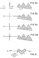
- the faces are ordered in such a manner that they can be displayed back to front, as shown in Fig. 4, and thus the visible faces which are closer to the viewpoint than the faces they occlude are displayed last.
- Such an ordering may be derived from a Binary Space Partition (BSP) tree which is viewpoint independent.
- BSP Binary Space Partition
- the construction of a BSP tree is computation intensive and requires a software preprocessing step which may require splitting faces.
- this method is not suitable for real-time interactive modelling systems.
- a depth buffer may be used to automatically select for each pixel the visible face.
- each pixel is associated with a storage location within the z-buffer which contains the depth of the currently displayed point, the depth typically being represented as a distance between the viewpoint and the displayed point.
- the depth of the projecting point is compared to the depth stored in the given pixel's memory location. If the new point is in front, that is, its depth is less than the depth stored in the pixel's memory, the new point is displayed and the pixel's memory is updated to reflect the new point's depth. Otherwise, the new point is ignored in that it lies behind an already displayed point and thus is not visible.
- Figs. 5a-5d This method is illustrated in Figs. 5a-5d for a plurality of points designated a, b and c.
- Fig. 5a the intensity for each pixel is set equal to a background intensity and the distance stored in the z-buffer is initially set equal to infinity or some large number.
- Fig. 5b a point "a” is processed. The intensity is made equal to that reflected by the point "a” and the distance stored in the z-buffer of the corresponding pixel is made equal to the distance from the view point to point "a”.
- Fig. 5c the point "b" is processed. In that the distance to "b” is less than the distance to "a” the point "b” is displayed and the intensity is made equal to that reflected by point "b".
- the depth of "b” is stored in the z-buffer memory.
- a point “c” is processed. In that the distance to point “c” along the z-axis is greater than the distance to point "b" currently stored int the z-buffer memory the point "c” is ignored and the final intensity of the point is that of point "b", which is the point visible through the corresponding pixel.
- One significant problem associated with the use of a BSP tree or of a conventional z-buffer is that the faces of the solid must be known. Since faces of the solid are not explicitly represented in the CSG tree they must be derived before they can be displayed. Such a derivation is known as a "boundary evaluation" and is a complex process which involves a large number of time consuming geometric calculations. Typically, the boundary evaluation process trims the faces of the primitive volumes by computing the solid's edges. Edges are computed by first generating curves, or pairwise intersections of surfaces, and then partitioning these curves accordingly to their intersections with all other primitive volume faces. Edges of the final solid are selected from this partition using the Boolean expression captured in the CSG tree.
- This boundary evaluation problem can be circumvented by employing a ray-casting algorithm, illustrated in Fig. 6, which computes lines, or rays, which pass through the viewpoint and the pixels of the screen model.
- the algorithm computes the intersection of each such ray with the solid.
- A being the closest to the viewpoint, is selected and the surface hit by the ray at that point is used to compute the associated pixel color.
- Computing the intersection of the ray with the solid may be accomplished by first classifying the ray against each primitive volume by partitioning the ray into segments that are entirely in, on, or out of the primitive volume and then by merging the results of these classifications up-the-tree according to the Boolean operators associated with the nodes of that tree.
- Such specialized hardware systems are generally substantially more costly and complex than a general purpose computer. Furthermore, these specialized systems by their nature do not address the problem of providing a fast and efficient method of shading CSG solids. Also, even for these specialized systems the aforementioned deficiencies in determining the faces and boundaries of a solid and in processing a CSG solid representation detrimentally impacts the speed of the system.
- depth-buffer algorithms To avoid the complex and expensive calculations involved in the merging step of the above mentioned ray-casting algorithm, and to fully use the hardware support for face scan-conversion and for viewing transformations when displaying CSG solids, depth-buffer algorithms have been proposed (Goldfeather et al., Jansen). These algorithms convert the CSG tree into a sum-of-product (disjunctive) form, where each product is the intersection of solid primitives or of their complements. In these algorithms, points on the faces of each primitive are compared, using a depth-buffer, to all other primitives in the product. Points that are not on the product are rejected after one of these comparisons. Remaining points are processed for display using a depth-buffer to select the visible points.
- the foregoing problems are overcome and other advantages are realized by, in accordance with the invention, apparatus and method for generating realistically shaded images or pictures of solids.
- the solids are of the type defined in CSG as Boolean combinations of simple primitive volumes.
- the invention readily detects interferences and differences between solids.
- An architecture of a system of the invention employs at least one pair of front and back depth-buffers which can be realized with pixel-parallel computer systems or efficiently simulated on scan-line computer systems used for computer graphics.
- the method of the invention extracts from CSG representations a particular form of Boolean expressions referred to as z-connected products.
- the use of z-connected product expressions in conjunction with pairs of front and back depth-buffers greatly reduces the amount of processing required to produce realistic shaded pictures of solid objects defined in CSG or to detect interferences or differences among such solids.
- the use of the invention significantly improves the performance of computer systems used for solid modelling and CAD/CAM applications.
- the invention is advantageously employed to produce shaded pictures of solids represented in CSG and to detect interferences and differences among two such solids.
- the invention utilizes a novel concept of z-connected sweeps and related concepts. These related concepts include the realization that a solid represented by any CSG tree may also be represented as a union of z-connected products and that these z-connected products may each be expressed as intersections of two z-connected sweeps. Furthermore it is shown that expressions of z-connected products in terms of sweeps can be extracted directly and efficiently from a CSG tree.
- the invention teaches that a volume occupied by any z-connected product is completely represented by two depth-buffers and that the intensity of light reflected by a z-connected product is stored in an intensity buffer.
- a triple-buffer representation, including two depth buffers and an intensity buffer, of a z-connected product is produced by scan converting but one time each z-connected sweep defining that product. Furthermore, during scan conversion, empty products and empty intersections of products with a particular line are readily detected.
- the invention further teaches that a final picture or image is readily obtained by merging a front buffer for each z-connected product to a conventional depth-buffer and that several sets of triple buffers may be employed to store intermediate products and improve the overall performance.
- processors each with a triple buffer, are operated in parallel to evaluate products and merge their respective results into a single z-buffer.
- Processes traverse the CSG tree and, without building an expanded sum-of-products tree, produce a description of each z-connected product. This description is a list of references to the front or the back primitive-faces that define each sweep.
- the z-buffer representation of each z-connected product is generated on the fly and requires that each primitive-face of a product be scan-converted but once.
- an intensity buffer is computed together with the depth-buffer representation of each z-connected product.
- the intensity buffer contains the image of the solid represented by the z-connected product.
- the representation of each product is incrementally integrated to the representation of the final picture.
- a general depth-buffer is used to select the visible contribution of each z-connected product by storing for each pixel the depth of the front-face of the z-connected product closest to the view-point.
- a general intensity buffer is also employed to store the image of the visible subsets of the front-faces of z-connected products.
- the method of the invention may be used for all pixels in parallel, in a manner similar to the aforementioned pixel-parallel algorithms, or for only a few rows of pixels at a time, using a scanline architecture.
- the invention provides for additional depth-buffers and intensity-buffers, grouped into triplets each of which includes a front depth-buffer, a back depth-buffer and an intensity-buffer, to process in one pass Boolean expressions that are not fully expanded into a union of z-connected products.
- additional depth-buffers and intensity-buffers grouped into triplets each of which includes a front depth-buffer, a back depth-buffer and an intensity-buffer, to process in one pass Boolean expressions that are not fully expanded into a union of z-connected products.
- the use of multiple buffer triplets reduces the total number of times each primitive-face is processed and even further enhances the overall efficiency and speed of the apparatus and method of the invention.
- certain of the algorithms disclosed herein require only two buffers (a front depth-buffer and an intensity buffer) and a one bit mask.
- the back depth-buffer which typically requires at least 24 bits of storage per pixel, can therefore be replaced with a smaller buffer of only one bit of storage per pixel. This saving is significant when depth-buffers for a full screen are used.
- a scan-line architecture system which is constructed in accordance with the invention automatically rejects z-connected products without processing all of the primitive faces or half spaces. This rejection occurs when a z-connected sweep, used in the definition of a z-connected product, does not intersect a row of pixels for which the display is calculated. The rejection also occurs when the projections on a row of the faces of all the z-connected sweeps already processed in a given z-connected product do not intersect. These intersections are determined in an incremental fashion by a scan-line display algorithm.
- a CSG representation is expressed in terms of a union of products, such that each product is the intersection of front or back sweeps and represents a set that exhibits a certain connectivity property. It will be shown how such a decomposition is derived from any CSG representation and methods are presented that employ such a decomposition.
- triple depth buffers, or z-buffers are shown to produce correctly shaded pictures or images and to also test for interference and difference directly from CSG. Furthermore the use of such a triple depth buffer in a scanline architecture will be described.
- a shaded picture of the solid can be produced by displaying each face and by using a z-buffer to eliminate hidden faces.
- the order in which the faces are displayed is not important in that the z-buffer will select the visible faces automatically.
- an attempt to display an additional face that lies inside a solid will have no effect on the image in that every point of the additional face lies behind at least one point of some front face of the solid.
- the use of a z-buffer is extended to shade solids, the solids being defined as the union of a finite number of possibly intersecting subsolids, referred to herein as products.
- the faces of the solid are a subset of the faces of all the products. Furthermore, any point on a product's face is either on the solid or inside of the solid.
- the z-buffer memory of this pixel contains the depth of the closest point. This depth is the minimum one of the depths of all points that project on the pixel. It should be noted that, in fact, only points on the front faces of each product must be considered.
- a standard coordinate system employed for computer generated graphics is defined such that the screen model is orthogonal to the Z-axis.
- a solid is said to be z-connected only if its intersection with any line parallel to the z-axis is connected (empty set, single point, or connected line segment).
- convex solids are z-connected, independently of their orientation, but non-convex solids may be z-connected or not, depending on their shape and on the viewpoint.
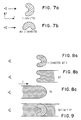
- Fig. 7a non-convex solid is z-connected while the same non-convex solid of Fig. 7b is not, due to the concave portion of the surface which is hidden from the viewpoint.
- the common primitive volumes can always be decomposed into z-connected sets.
- Blocks, spheres, cylinders and half cones are convex solids and thus always z-connected.
- a torus is an example of a non-convex primitive volume that is z-connected when its axis of symmetry forms a sufficiently small angle with the Z-axis. However, when that angle exceeds a certain value the torus is no longer z-connected. It can however be decomposed into two separate z-connected volumes. Although it is possible to obtain such a decomposition without introducing any new front or back faces, it is generally much simpler to cut the torus into two equal halves that are z-connected.
- Fig. 8a there is shown a z-connected set S.
- Fig. 8b shows that the front sweep, Sf, of the solid S is that region of space swept by S as it moves in a positive z-direction, or away from the viewpoint, starting at its initial position and going to infinity.
- Fig. 8c shows that a back sweep, Sb, of S is that region of space swept by S as it moves in the negative z-direction, or towards the viewpoint, starting at its initial position and going to infinity.
- Sf and Sb are unbounded z-connected sets.
- S is equal to the intersection of Sf with Sb.
- complements of front or back sweeps are z-connected and that the intersection P of any number of front or back sweeps is z-connected. Consequently, the intersection may be represented as the intersection of only two sweeps Pf and Pb, a front sweep and a back sweep, respectively, of P.
- Pf is entirely represented by its front faces in that it has no back faces.
- Pb is entirely represented by its back faces. Consequently, within the accuracy dictated by the resolution, or number of pixels, of the display screen Pf and Pb may each be represented by a single z-buffer Zf and Zb, respectively.
- any CSG tree may be expressed as a union of products such that each product P is the intersection of a number of front sweeps with a number of back sweeps.
- the shading and the interference and difference detection processes employ the z-buffer representation of such a product which is constructed by employing the two z-buffers F and B.
- the contents of F are determined by storing for each pixel the minimum depth of all points of the front faces of the sweeps defining Pf that project on that pixel.
- the contents of B are determined by storing for each pixel the maximum depth of all points of the back faces of the sweeps defining Pb that project on that pixel.
- F and B determined as indicated above, represent the intersection of all front and back sweeps, respectively, which define P.
- P has been previously shown to be the intersection of Pb with Pf.
- the front faces of P are contained in, but need not be equal to, the front faces stored in F as shown in Fig. 10.
- the front faces of P are equal to that portion of the front faces stored in F that lie in front of the back faces stored in B. Consequently, the extent of the front faces of P are determined by comparing, for each pixel, the depth stored in F with the depth stored in B.
- a pixel memory 12 may be a full frame buffer for an entire display screen 14 or a line buffer for a scan-line type system. In either case, for each pixel stored in the pixel memory 12 there are five storage entries grouped into five buffers.
- One of these buffers is a temporary front z-buffer (F) 16 which is employed to store the depths of the front face for the currently processed z-connected product.
- Another of these buffers is a temporary back z-buffer (B) 18 which stores the depths of the back face for the currently processed z-connected product.
- Another buffer is a final z-buffer (Z) 20 which is used to store the depths associated with the front faces of the entire displayed solid.
- Two other buffers are a temporary intensity buffer (T) 22 for storing the intensities of the current product and a final intensity buffer (I) 24 for storing the intensities of the visible faces of the entire displayed solid.
- a bus 26 couples these various buffers together and to a processor 28 which may be a central processing unit or a peripheral processor dedicated to managing the buffers and for executing instructions for accomplishing the method of the invention.
- the processor 28 has an associated memory 30 for storage of the CSG tree structure which defines a displayed solid in addition to storing other data and instructions required for managing the buffers and display, operator interaction and other processor 28 functions.
- the pixel memory 12 may be organized in a number of manners and may include, for example, 24 planes of single bit storage locations for defining a 24 bit pixel word associated with each of the z-buffers and intensity buffers.
- the processor 28 traverses the original CSG tree and processes each z-connected product separately. For a given product, the contents of the F 16, B 18 and T 22 buffers are determined by incorporating the contribution of each sweep to the z-connected product. After all front and back sweeps of the product are processed, the result is incorporated into the final Z 20 and I 24 buffers.
- An algorithm descriptive of this method for a scanline architecture system is described below, it being realized that the algorithm is repeated for each row of pixels.
- Fig. 12 is a flow chart of the operation of the above set forth algorithm, in the case where full frame buffers and Z-buffers are used as opposed to the scan line approach.
- apparatus and method for performing interference or difference detection to, for example, determine if two solids A and B interfere or if they are identical.
- a modified version of the display algorithm set forth above is applied to the CSG representation of A ⁇ B or of [(A-B) union (B-A)]. This determination does not require a final Z-buffer 20 nor any intensity buffers 22 and 24 in that it evaluates each product until a non-empty product is detected.
- each primitive volume, or half space, that is not z-connected is replaced by a union of z-connected subvolumes.
- each primitive volume, or half-space is replaced by the intersection of its front sweep with its back sweep.
- each difference operator in the tree is replaced by an intersection operator and the right subtree of that operator is complemented.
- the step of complementing the right subtree transforms the subtree into an equivalent subtree by applying de Morgan's laws of complementation. Complemented front sweeps are called backsweeps and vice versa.
- the invention provides for, instead of building a new tree, utilizing the original CSG tree to produce the list of the front and back sweeps which constitute the elements of each product thereby providing a significant saving in the amount of storage necessary for the process.
- the successive terms of the disjunctive normal form are generated "on the fly" by repeatedly traversing the original tree.
- the method performs a preorder tree traversal propagating the sign of each node through recursive calls.
- the method traverses the original CSG tree in a top down manner.
- the equivalent operator is an intersection, both the left and the right children are visited recursively.
- the equivalent operator is a union, only one child is visited, which one depending on which product is computed.
- the corresponding literal, or primitive of the original tree and its sign is processed by display algorithms.
- a direction flag is initialized to point to the left child.
- the flag is changed to point to the right child.
- the flag is changed to point to the left child again. This process is repeated until all of the products have been generated.
- each processor is associated with a triple buffer.
- the expressions defining z-connected products are dispatched to the different processors, which construct, in parallel, the triple buffer representations of their product.
- a particular processor completes the evaluation of a z-connected product, it merges the result into a common z-buffer, and is ready to process the next product.
- the total number of times that a face of a primitive volume A must be scan converted is a function of the number of z-connected products containing A, i.e. on the form of the expanded CSG tree.
- the teaching of the invention further improves the performance of processing CSG trees by avoiding the generation of all products for certain subtrees. That is, the invention provides techniques for processing certain CSG trees that are not in the sum-of-products form with a consequent reduction in the number of scan-conversions required for each primitive. More particularly, there is defined a class of sub-trees which are processed without scan-converting any primitive face more than once.
- these processes include a process using three z-buffers and two intensity buffers and another process using four z-buffers and three intensity buffers.
- CSG expressions that are amenable to being processed without repetitive scanning.
- additional buffers is advantageously employed to further reduce the number of times each primitive is scan-converted, and in particular permits the processing of a larger class of subtrees without scan-converting any primitive face in a product more than once.
- scan-converting is a known process which, based on the defined screen coordinates of a polygon, successively scans the polygon to generate a list of points covering pixels upon which the polygon projects.
- the list of pixels includes the x-y position of each pixel in addition to a depth along the z-axis of a point on the polygon referenced to the pixel. In conventional systems this depth is stored in the single depth or z-buffer location associated with each pixel upon which the polygon projects.
- the depth used is the maximum depth value when the scanned face is a front face of a positive primitive or a back face of a negative primitive. Otherwise, the minimum depth value is used.
- a z-connected product can be represented by two z-buffers. It will now further be shown that the complement of a z-connected product is also representable by two z-buffers and that the front face of a product of sets that are either z-connected front and back sweeps or complements of z-connected sets is determinable with only two z-buffers and one temporary intensity buffer, requiring that uncomplemented sweeps be scan-converted only once. It will also further be shown that the front face of the difference of two z-connected products, when the first product has only one front sweep, is determinable by using only two z-buffers and a temporary intensity buffer, and requires scan-converting each sweep only once.
- a z-connected set is represented by its front and its back sweeps
- the complement of the solid is also represented by the same two sweeps, provided that it is known when the two sweeps represent the bounded solid or its complement.
- each subtree that is expressible as the intersection of leaves that are z-connected sets or complements of z-connected sets.
- such subtrees occur if one simplifies the process described above for extracting z-connected products from CSG. Specifically, primitives volumes are treated as literals and need not be considered as intersections of their front and back sweeps in the expansion process. The result is a sum-of-products where each product is the intersection of positive or negative primitives, and needs not be z-connected. Each one such product can be written as P*Q1*Q2*..*Qk. Each such product is processed in accordance with the block diagram of Fig. 11a and the flow chart of Fig. 14 by the following method.
- A denote a primitive, or more generally the intersection of a single front sweep with a finite set of back sweeps.
- the difference A-P is determined, scan-converting each face only once, using only the two z-buffers F 16 and B 18 and the temporary intensity buffer T 22, by the following steps which are also illustrated in the flow chart of Fig. 15.
- a and P denote products of front and back sweeps.
- the difference A-P is determined, scan converting each face only once, using the three z-buffers F 16, B 18 and Z 20 and the two intensity buffers T 22 and I 24 by the following steps which are also illustrated in the flow chart of Fig. 16.
- each face is scan-converted only once.
- Solids defined in CSG as a union of differences of two products, where except for the first difference, the first product of each difference has only one front sweep, are determined using only three z-buffers and two intensity buffers because, as shown above, the first difference is determined using all five buffers while subsequent differences require only two z-buffers and one intensity buffer.
- solids defined in CSG as a union of differences of two z-connected products are processed, for display or null object detection, by scan-converting each face of each primitive volume only once, as described above.
- Each difference of products is processed using three z-buffers and two intensity buffers as described above, and the results are thereafter integrated into the fourth global z-buffer 32 and a third global intensity buffer 34.
- the invention as set forth above may be practiced in a number of physical embodiments including, but not limited to, graphics processing systems of the parallel or scan-line type having dedicated buffers implemented in hardware.
- the invention may also be practiced with a general purpose computer wherein the various z-buffers and intensity buffers are allocated regions of memory.
- certain methods of the invention as set forth above may be practiced using a modified embodiment wherein the back buffer B is not necessary or is replaced with a smaller buffer having only one bit of storage per pixel.
- the front faces of a product of front and back sweeps can be computed using only the front buffer F 16 and the intensity buffer T 22 and not using the back buffer B 18 at all by the following method, which is a variation of the method depicted in Fig. 12.
- the back sweeps are used one at a time to trim F 16 directly.
- F 16 is replaced by the maximum representable depth at pixels where the depth stored in F 16 exceeds the depth generated by the scan-conversion, taking into account that the minimum depth value is used for pixels not covered by the face.
Landscapes
- Physics & Mathematics (AREA)
- Engineering & Computer Science (AREA)
- Geometry (AREA)
- Computer Graphics (AREA)
- General Physics & Mathematics (AREA)
- Theoretical Computer Science (AREA)
- Image Generation (AREA)
Applications Claiming Priority (2)
| Application Number | Priority Date | Filing Date | Title |
|---|---|---|---|
| US340322 | 1989-04-19 | ||
| US07/340,322 US5027292A (en) | 1989-04-19 | 1989-04-19 | Multiple depth buffers for graphics and solid modelling |
Publications (2)
| Publication Number | Publication Date |
|---|---|
| EP0393309A1 EP0393309A1 (en) | 1990-10-24 |
| EP0393309B1 true EP0393309B1 (en) | 1995-07-12 |
Family
ID=23332855
Family Applications (1)
| Application Number | Title | Priority Date | Filing Date |
|---|---|---|---|
| EP90100993A Expired - Lifetime EP0393309B1 (en) | 1989-04-19 | 1990-01-18 | Multiple depth buffers for graphics and solid modelling |
Country Status (5)
| Country | Link |
|---|---|
| US (1) | US5027292A (ja) |
| EP (1) | EP0393309B1 (ja) |
| JP (1) | JPH0727579B2 (ja) |
| CA (1) | CA2007790C (ja) |
| DE (1) | DE69020780T2 (ja) |
Families Citing this family (29)
| Publication number | Priority date | Publication date | Assignee | Title |
|---|---|---|---|---|
| CA2055532A1 (en) * | 1990-11-26 | 1992-05-27 | Xingzhang F. Niu | Enhanced solid model generation |
| JPH07122908B2 (ja) * | 1991-03-12 | 1995-12-25 | インターナショナル・ビジネス・マシーンズ・コーポレイション | 3次元のソリッド物体を表す表示可能情報を生成する装置と方法 |
| DE69233717T2 (de) * | 1991-06-28 | 2008-10-30 | Lim, Hong Lip, Darlington | Verbesserungen in sichtbarkeit-berechnungen fuer 3d-rechner |
| US5274760A (en) * | 1991-12-24 | 1993-12-28 | International Business Machines Corporation | Extendable multiple image-buffer for graphics systems |
| US5428716A (en) * | 1991-12-26 | 1995-06-27 | International Business Machines Corporation | Solid-clip methodology and architecture for clipping solid models and displaying cross-sections using depth-buffers |
| US5377313A (en) * | 1992-01-29 | 1994-12-27 | International Business Machines Corporation | Computer graphics display method and system with shadow generation |
| DE4303071A1 (de) * | 1992-02-03 | 1993-10-28 | Computervision Corp | Verfahren und Vorrichtung zur Randbewertung in einer Nicht-Mannigfaltigkeits-Umgebung |
| US5497453A (en) * | 1993-01-05 | 1996-03-05 | International Business Machines Corporation | Method and apparatus for detecting and visualizing interferences between solids |
| WO1994027240A1 (en) * | 1993-05-10 | 1994-11-24 | Apple Computer, Inc. | Computer graphics system having high performance multiple layer z-buffer |
| US5583974A (en) * | 1993-05-10 | 1996-12-10 | Apple Computer, Inc. | Computer graphics system having high performance multiple layer Z-buffer |
| US5684939A (en) * | 1993-07-09 | 1997-11-04 | Silicon Graphics, Inc. | Antialiased imaging with improved pixel supersampling |
| US5729672A (en) * | 1993-07-30 | 1998-03-17 | Videologic Limited | Ray tracing method and apparatus for projecting rays through an object represented by a set of infinite surfaces |
| GB9315852D0 (en) * | 1993-07-30 | 1993-09-15 | Video Logic Ltd | Shading three-dimensional images |
| JP2616882B2 (ja) * | 1993-12-17 | 1997-06-04 | 日本アイ・ビー・エム株式会社 | 非多様体データ構造に基づく数値制御加工シミュレーション・システム及び方法 |
| EP0725365B1 (en) * | 1995-01-31 | 2002-06-05 | Imagination Technologies Limited | Method and apparatus for shading three-dimensional images |
| JPH0969163A (ja) * | 1995-08-31 | 1997-03-11 | Fujitsu Ltd | コンピュータグラフィックスモデルのポリゴン重なり抽出方法と、ポリゴンのグループ化方法及び装置 |
| US7225404B1 (en) * | 1996-04-04 | 2007-05-29 | Massachusetts Institute Of Technology | Method and apparatus for determining forces to be applied to a user through a haptic interface |
| US6084587A (en) * | 1996-08-02 | 2000-07-04 | Sensable Technologies, Inc. | Method and apparatus for generating and interfacing with a haptic virtual reality environment |
| US5926182A (en) * | 1996-11-19 | 1999-07-20 | International Business Machines Corporation | Efficient rendering utilizing user defined shields and windows |
| US5926183A (en) * | 1996-11-19 | 1999-07-20 | International Business Machines Corporation | Efficient rendering utilizing user defined rooms and windows |
| US6249600B1 (en) * | 1997-11-07 | 2001-06-19 | The Trustees Of Columbia University In The City Of New York | System and method for generation of a three-dimensional solid model |
| US6421048B1 (en) | 1998-07-17 | 2002-07-16 | Sensable Technologies, Inc. | Systems and methods for interacting with virtual objects in a haptic virtual reality environment |
| US6552722B1 (en) * | 1998-07-17 | 2003-04-22 | Sensable Technologies, Inc. | Systems and methods for sculpting virtual objects in a haptic virtual reality environment |
| US7030877B1 (en) * | 2002-03-04 | 2006-04-18 | Advanced Micro Devices, Inc. | Computer graphics processing system, computer memory, and method of use with computer graphics processing system utilizing hierarchical image depth buffer |
| WO2006004894A2 (en) | 2004-06-29 | 2006-01-12 | Sensable Technologies, Inc. | Apparatus and methods for haptic rendering using data in a graphics pipeline |
| US8208764B2 (en) * | 2006-01-21 | 2012-06-26 | Elizabeth Guckenberger | Photo automatic linking system and method for accessing, linking, and visualizing “key-face” and/or multiple similar facial images along with associated electronic data via a facial image recognition search engine |
| ES2671457T3 (es) | 2011-04-21 | 2018-06-06 | Sergei Vladimirovich Lukyanets | Cilindro de alta presión de materiales compuestos |
| US9111071B2 (en) * | 2012-11-05 | 2015-08-18 | Sap Se | Expression rewriting for secure computation optimization |
| GB2520365B (en) | 2013-12-13 | 2015-12-09 | Imagination Tech Ltd | Primitive processing in a graphics processing system |
Family Cites Families (6)
| Publication number | Priority date | Publication date | Assignee | Title |
|---|---|---|---|---|
| US4649498A (en) * | 1984-05-08 | 1987-03-10 | The University Of Rochester | Computer systems for curve-solid classification and solid modeling |
| US4736306A (en) * | 1985-04-29 | 1988-04-05 | The United States Of America As Represented By The United States Department Of Energy | System for conversion between the boundary representation model and a constructive solid geometry model of an object |
| US4821214A (en) * | 1986-04-17 | 1989-04-11 | Brigham Young University | Computer graphics method for changing the shape of a geometric model using free-form deformation |
| JPH0634239B2 (ja) * | 1986-06-16 | 1994-05-02 | 工業技術院長 | 3次元画像表示装置 |
| GB2194656B (en) * | 1986-09-03 | 1991-10-09 | Ibm | Method and system for solid modelling |
| US4888583A (en) * | 1988-03-14 | 1989-12-19 | Ligocki Terry J | Method and apparatus for rendering an image from data arranged in a constructive solid geometry format |
-
1989
- 1989-04-19 US US07/340,322 patent/US5027292A/en not_active Expired - Fee Related
-
1990
- 1990-01-15 CA CA002007790A patent/CA2007790C/en not_active Expired - Fee Related
- 1990-01-18 DE DE69020780T patent/DE69020780T2/de not_active Expired - Fee Related
- 1990-01-18 EP EP90100993A patent/EP0393309B1/en not_active Expired - Lifetime
- 1990-04-17 JP JP2099450A patent/JPH0727579B2/ja not_active Expired - Lifetime
Also Published As
| Publication number | Publication date |
|---|---|
| EP0393309A1 (en) | 1990-10-24 |
| DE69020780D1 (de) | 1995-08-17 |
| JPH0362276A (ja) | 1991-03-18 |
| CA2007790C (en) | 1994-03-29 |
| JPH0727579B2 (ja) | 1995-03-29 |
| DE69020780T2 (de) | 1996-03-14 |
| US5027292A (en) | 1991-06-25 |
| CA2007790A1 (en) | 1990-10-19 |
Similar Documents
| Publication | Publication Date | Title |
|---|---|---|
| EP0393309B1 (en) | Multiple depth buffers for graphics and solid modelling | |
| US6023279A (en) | Method and apparatus for rapidly rendering computer generated images of complex structures | |
| Van Hook | Real-time shaded NC milling display | |
| US6373485B2 (en) | Mitigating the effects of object approximations | |
| US5442733A (en) | Method and apparatus for generating realistic images using a discrete representation | |
| US6300965B1 (en) | Visible-object determination for interactive visualization | |
| US5497453A (en) | Method and apparatus for detecting and visualizing interferences between solids | |
| US5222202A (en) | Method and apparatus for visualization of iso-valued surfaces | |
| Dorward | A survey of object-space hidden surface removal | |
| WO2002054351A2 (en) | Using ancillary geometry for visibility determination | |
| JPH05266212A (ja) | データプロセッサによってオブジェクトの作成を実行する方法及びグラフィックスディスプレイ装置 | |
| JPH0776989B2 (ja) | 3次元物体の2次元イメージ発生方法及びその装置 | |
| GB2194656A (en) | Solid modelling | |
| JPH0620012A (ja) | 科学的図形表示方法 | |
| Plate et al. | A flexible multi-volume shader framework for arbitrarily intersecting multi-resolution datasets | |
| Scherson et al. | Data structures and the time complexity of ray tracing | |
| Schollmeyer et al. | Efficient and anti-aliased trimming for rendering large NURBS models | |
| Hable et al. | Cst: Constructive solid trimming for rendering breps and csg | |
| US20030160776A1 (en) | Geometric folding for cone-tree data compression | |
| Woodwark | Generating wireframes from set-theoretic solid models by spatial division | |
| Jansen | Solid modelling with faceted primitives | |
| Gervautz | Three improvements of the ray tracing algorithm for CSG trees | |
| Maurel et al. | A 4D ray tracing | |
| Bittner | Hierarchical techniques for visibility determination | |
| Bronsvoort et al. | Design and display of solid models |
Legal Events
| Date | Code | Title | Description |
|---|---|---|---|
| PUAI | Public reference made under article 153(3) epc to a published international application that has entered the european phase |
Free format text: ORIGINAL CODE: 0009012 |
|
| AK | Designated contracting states |
Kind code of ref document: A1 Designated state(s): DE FR GB IT |
|
| 17P | Request for examination filed |
Effective date: 19901213 |
|
| 17Q | First examination report despatched |
Effective date: 19930728 |
|
| GRAA | (expected) grant |
Free format text: ORIGINAL CODE: 0009210 |
|
| AK | Designated contracting states |
Kind code of ref document: B1 Designated state(s): DE FR GB IT |
|
| PG25 | Lapsed in a contracting state [announced via postgrant information from national office to epo] |
Ref country code: IT Free format text: LAPSE BECAUSE OF FAILURE TO SUBMIT A TRANSLATION OF THE DESCRIPTION OR TO PAY THE FEE WITHIN THE PRE;WARNING: LAPSES OF ITALIAN PATENTS WITH EFFECTIVE DATE BEFORE 2007 MAY HAVE OCCURRED AT ANY TIME BEFORE 2007. THE CORRECT EFFECTIVE DATE MAY BE DIFFERENT FROM THE ONE RECORDED.SCRIBED TIME-LIMIT Effective date: 19950712 |
|
| REF | Corresponds to: |
Ref document number: 69020780 Country of ref document: DE Date of ref document: 19950817 |
|
| ET | Fr: translation filed | ||
| PLBE | No opposition filed within time limit |
Free format text: ORIGINAL CODE: 0009261 |
|
| STAA | Information on the status of an ep patent application or granted ep patent |
Free format text: STATUS: NO OPPOSITION FILED WITHIN TIME LIMIT |
|
| 26N | No opposition filed | ||
| PG25 | Lapsed in a contracting state [announced via postgrant information from national office to epo] |
Ref country code: FR Effective date: 19960930 |
|
| PG25 | Lapsed in a contracting state [announced via postgrant information from national office to epo] |
Ref country code: DE Effective date: 19961001 |
|
| REG | Reference to a national code |
Ref country code: FR Ref legal event code: ST |
|
| PGFP | Annual fee paid to national office [announced via postgrant information from national office to epo] |
Ref country code: GB Payment date: 19971217 Year of fee payment: 9 |
|
| PG25 | Lapsed in a contracting state [announced via postgrant information from national office to epo] |
Ref country code: GB Free format text: LAPSE BECAUSE OF NON-PAYMENT OF DUE FEES Effective date: 19990118 |
|
| GBPC | Gb: european patent ceased through non-payment of renewal fee |
Effective date: 19990118 |