EP0390232A2 - Procédé et appareil de contrôle de l'étanchéité d'une enceinte - Google Patents
Procédé et appareil de contrôle de l'étanchéité d'une enceinte Download PDFInfo
- Publication number
- EP0390232A2 EP0390232A2 EP90200274A EP90200274A EP0390232A2 EP 0390232 A2 EP0390232 A2 EP 0390232A2 EP 90200274 A EP90200274 A EP 90200274A EP 90200274 A EP90200274 A EP 90200274A EP 0390232 A2 EP0390232 A2 EP 0390232A2
- Authority
- EP
- European Patent Office
- Prior art keywords
- container
- signal
- casing
- chamber
- wall
- Prior art date
- Legal status (The legal status is an assumption and is not a legal conclusion. Google has not performed a legal analysis and makes no representation as to the accuracy of the status listed.)
- Granted
Links
Images

Classifications
-
- G—PHYSICS
- G01—MEASURING; TESTING
- G01M—TESTING STATIC OR DYNAMIC BALANCE OF MACHINES OR STRUCTURES; TESTING OF STRUCTURES OR APPARATUS, NOT OTHERWISE PROVIDED FOR
- G01M3/00—Investigating fluid-tightness of structures
- G01M3/02—Investigating fluid-tightness of structures by using fluid or vacuum
- G01M3/04—Investigating fluid-tightness of structures by using fluid or vacuum by detecting the presence of fluid at the leakage point
- G01M3/06—Investigating fluid-tightness of structures by using fluid or vacuum by detecting the presence of fluid at the leakage point by observing bubbles in a liquid pool
- G01M3/10—Investigating fluid-tightness of structures by using fluid or vacuum by detecting the presence of fluid at the leakage point by observing bubbles in a liquid pool for containers, e.g. radiators
- G01M3/106—Investigating fluid-tightness of structures by using fluid or vacuum by detecting the presence of fluid at the leakage point by observing bubbles in a liquid pool for containers, e.g. radiators for radiators
-
- G—PHYSICS
- G01—MEASURING; TESTING
- G01M—TESTING STATIC OR DYNAMIC BALANCE OF MACHINES OR STRUCTURES; TESTING OF STRUCTURES OR APPARATUS, NOT OTHERWISE PROVIDED FOR
- G01M3/00—Investigating fluid-tightness of structures
- G01M3/02—Investigating fluid-tightness of structures by using fluid or vacuum
- G01M3/04—Investigating fluid-tightness of structures by using fluid or vacuum by detecting the presence of fluid at the leakage point
- G01M3/06—Investigating fluid-tightness of structures by using fluid or vacuum by detecting the presence of fluid at the leakage point by observing bubbles in a liquid pool
- G01M3/10—Investigating fluid-tightness of structures by using fluid or vacuum by detecting the presence of fluid at the leakage point by observing bubbles in a liquid pool for containers, e.g. radiators
Definitions
- the invention relates to a process according to the preamble of Claim 1, and a device for carrying out said process according to the preamble of Claim 2.
- Method and device are known from practice.
- the object of the invention is to eliminate this drawback and provide a process and device of the above-mentioned kind with which all leaks present are detected with absolute certainty.
- band-pass filters placed in the path of the signal supplied by the vibration sensor in combination with the insulation of the interior of the chamber for sound and vibrations with frequencies, relevant for detecting the leak, makes the device in a high degree insensitive for external disturbances and thus increases the sensitivity considerable.
- US-A-2 961 869 describes the use of amplifier- and filtercircuits in a leak detection device which is based on a completely different principle, namely: emitting high frequency vibrations in a container filled with liquid in which the casing to be tested is placed and detecting vibrations reflected by emerging gasbubbles.
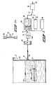
- Fig. 1 indicates by reference number 2 a container which is partially filled with a liquid medium 4, for example water, and in which a casing 6, whose tightness is to be checked, is immersed. Prior to the immersion, the casing 6 is filled with a compressed medium, for example air.
- a vibration-sensitive sensor 8 Fixed on the wall 2a of the container 2 is a vibration-sensitive sensor 8, for example a piezoelectric sensor which delivers electrical output signals to the connection 10 whose amplitude and frequency correspond to those of the vibrations picked up by said sensor.
- Figure 1 a shows a preferred way of positioning the piezo-electric sensor according to which this sensor 8 is fixed to a thinner wall part 3 in the wall 2a. The fixing can be done in any suitable way, for instance by gluing or by means of mechanical fastening elements.
- the electrical signals are fed to an amplification stage 12, the output of which is connected to an adjustable band-pass filter which by means of the selector switch 14a can be set at central frequencies of approximately 2, 4 and 8 KHz; the passed signals are fed to an evaluation circuit by means of a two-position switch 11.
- This evaluating circuit can comprise a monitor 16 with output terminal 18 which is connected with the uppermost terminal of the two-position switch 17. By means of this monitor one observes whether or not the signal at its input which, as said, represents the vibrations detected by the sensor 8 exceeds the background noise signal with a certain amount, for instance 10 dB. This obsering can be done visually but the monitor 18 can also be constructed in such a way that its output terminal 18 carries a signal of predetermined amplitude and shape when this condition is met.
- the evaluating circuit can also be based on comparing as to wave form and amplitude the measuring signal, as this occurs at the input terminal of the switch 18 with a reference signal which is obtained by positioning in the container 2 a casing with a predetermined, known leak and by recording, for instance magnetically or optically, the signal which then arises.
- Reference numeral 15 schematically shows such a reference signal source which generates this recorded reference signal and its outputsignal is supplied to the comparing circuit 13 to which in the lower position of the switch 11 also the measuring signal is supplied; when there is coincidence - which points to the presence of a leak - the output 19 of the comparing circuit carries a signal which indicates the presence of a leak.
- the outputsignals of monitor 16 and comparing circuit 13 respectively are supplied via the two-position switch 17 to a controlcircuit 21 of which the signal, present at its output terminal 23, determines the destination of the leaking casing in a way which will be described later on.
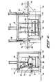
- Process and device according to the invention are particularly suitable for use in a continuous testing process, to be carried out at the end of a production line. This is shown schematically for radiators in Fig. 2,
- Fig. 2 shows how the container 2 is placed on vibration insulators 26a, 26b on the bottom 28 of a sound-insulated (chamber which itself rests by means of a suitable) number of vibration insulators on a foundation 34.
- the radiators to be tested are conveyed in on a feed belt 36, subsequently tested (as indicated for the radiator 6b), and discharged onto a discharge belt 38, as indicated for the radiator 6c.
- radiators can be placed under excess pressure outside the test chamber, prior to immersion in the container 2, and then shut off, but it is also possible to connect each radiator to be tested, after it has passed into the test chamber, to a compressed air source of the type shown schematically by the compressed air connection 40, the hose 42 and the reducing valve with connection 44.
- a roller track part 46 connected by suitable suspension means to the control rod 48 of a hydraulic or pneumatic working cylinder 50 is used to lower the radiators for testing into the container 2 and remove them therefrom.
- Shut-off doors 52, 54 which can be moved up and down in the vertical direction, and which are suspended from the working cylinders 56, 58, complete the plant.
- the testing process is simple: after the placing of a radiator, such as the radiator 6b, in the test chamber, the connection between reducing valve 44 and the connection branch 6b of the radiator 6b is made, following which the doors 52 and 54 are closed, and the signals delivered by the vibration sensor 8 are picked up and evaluated. On completion of the test the doors 52 and 54 are opened, the connection to the branch 6b is released, the radiator 6b is removed from the chamber,' and a new radiator is fed into the chamber.
- a radiator such as the radiator 6b
- Fig. 3 shows how such a plant can be installed in a simple manner at the end of a production line for radiators.
- the chamber 30 is provided between the feed conveyor 36 and the discharge conveyor 38; if the output signal occurring at the output 18 of the monitor 16 indicates that a tested radiator has been found satisfactory, it is discharged there in the direction of the arrow 60 on the conveyor 38, but if a signal which indicates the presence of a leak is encountered, the tested radiator is discharged in the direction of the arrow 62 via the transverse conveyor belt 64 to the conveyor belt 66, where an inspection and repair station 68 is located for further inspection on the radiator in question and possible carrying out of repairs on it.
Landscapes
- Physics & Mathematics (AREA)
- General Physics & Mathematics (AREA)
- Examining Or Testing Airtightness (AREA)
- Sealing Battery Cases Or Jackets (AREA)
- Measurement Of Mechanical Vibrations Or Ultrasonic Waves (AREA)
Priority Applications (1)
| Application Number | Priority Date | Filing Date | Title |
|---|---|---|---|
| AT90200274T ATE81202T1 (de) | 1989-02-07 | 1990-02-06 | Verfahren und vorrichtung zum dichtheitspruefen von behaeltern. |
Applications Claiming Priority (2)
| Application Number | Priority Date | Filing Date | Title |
|---|---|---|---|
| NL8900301A NL8900301A (nl) | 1989-02-07 | 1989-02-07 | Werkwijze voor het controleren van de dichtheid van een omhulsel en inrichting voor het uitvoeren van deze werkwijze. |
| NL8900301 | 1989-02-07 |
Publications (3)
| Publication Number | Publication Date |
|---|---|
| EP0390232A2 true EP0390232A2 (fr) | 1990-10-03 |
| EP0390232A3 EP0390232A3 (en) | 1990-10-10 |
| EP0390232B1 EP0390232B1 (fr) | 1992-09-30 |
Family
ID=19854093
Family Applications (1)
| Application Number | Title | Priority Date | Filing Date |
|---|---|---|---|
| EP90200274A Expired - Lifetime EP0390232B1 (fr) | 1989-02-07 | 1990-02-06 | Procédé et appareil de contrôle de l'étanchéité d'une enceinte |
Country Status (5)
| Country | Link |
|---|---|
| EP (1) | EP0390232B1 (fr) |
| AT (1) | ATE81202T1 (fr) |
| DE (1) | DE69000345T2 (fr) |
| ES (1) | ES2034810T3 (fr) |
| NL (1) | NL8900301A (fr) |
Cited By (2)
| Publication number | Priority date | Publication date | Assignee | Title |
|---|---|---|---|---|
| EP0522357A1 (fr) * | 1991-06-28 | 1993-01-13 | Hoechst Aktiengesellschaft | Méthode qualitative et quantitative pour tester l'étanchéité des pièces creuses |
| WO2016209187A1 (fr) * | 2015-06-25 | 2016-12-29 | Floteks Plastik Sanayi Ve Ticaret Anonim Sirketi | Mécanisme de test de fuite |
Families Citing this family (1)
| Publication number | Priority date | Publication date | Assignee | Title |
|---|---|---|---|---|
| US5369983A (en) * | 1992-04-17 | 1994-12-06 | Minnesota Mining And Manufacturing Company | Detection medium and method for use in hermetic seal testing |
Citations (4)
| Publication number | Priority date | Publication date | Assignee | Title |
|---|---|---|---|---|
| FR1495004A (fr) * | 1966-08-05 | 1967-09-15 | Chausson Usines Sa | Installation pour le contrôle de l'étanchéité de pièces d'ouvrage creuses, notamment de radiateurs de refroidissement et pour l'établissement d'états de contrôle |
| JPS57137836A (en) * | 1981-02-20 | 1982-08-25 | Hitachi Ltd | Leakage detector |
| SU966516A1 (ru) * | 1981-03-26 | 1982-10-15 | Институт Прикладной Физики Ан Бсср | Способ контрол герметичности полых изделий |
| JPS6063438A (ja) * | 1983-09-17 | 1985-04-11 | Nichiei Boeki Kk | 漏洩探知方法及び装置 |
-
1989
- 1989-02-07 NL NL8900301A patent/NL8900301A/nl not_active Application Discontinuation
-
1990
- 1990-02-06 EP EP90200274A patent/EP0390232B1/fr not_active Expired - Lifetime
- 1990-02-06 ES ES199090200274T patent/ES2034810T3/es not_active Expired - Lifetime
- 1990-02-06 DE DE9090200274T patent/DE69000345T2/de not_active Expired - Fee Related
- 1990-02-06 AT AT90200274T patent/ATE81202T1/de not_active IP Right Cessation
Patent Citations (4)
| Publication number | Priority date | Publication date | Assignee | Title |
|---|---|---|---|---|
| FR1495004A (fr) * | 1966-08-05 | 1967-09-15 | Chausson Usines Sa | Installation pour le contrôle de l'étanchéité de pièces d'ouvrage creuses, notamment de radiateurs de refroidissement et pour l'établissement d'états de contrôle |
| JPS57137836A (en) * | 1981-02-20 | 1982-08-25 | Hitachi Ltd | Leakage detector |
| SU966516A1 (ru) * | 1981-03-26 | 1982-10-15 | Институт Прикладной Физики Ан Бсср | Способ контрол герметичности полых изделий |
| JPS6063438A (ja) * | 1983-09-17 | 1985-04-11 | Nichiei Boeki Kk | 漏洩探知方法及び装置 |
Non-Patent Citations (3)
| Title |
|---|
| PATENT ABSTRACTS OF JAPAN, vol. 6, no. 237 (P-157)[1115], 25th November 1982; & JP-A-57 137 836 (HITACHI SEISAKUSHO K.K.) 25-08-1982 * |
| PATENT ABSTRACTS OF JAPAN, vol. 9, no. 199 (P-380)[1922], 16th August 1985; & JP-A-60 63 438 (NICHIEI BOUEKI K.K.) 11-04-1985 * |
| SOVIET INVENTIONS ILLUSTRATED DERWENT, week K32, 21st September 1983, Derwent Publications Ltd, London, GB; & SU-A-966 516 (AS BELO APPL. PHYS.) 15-10-1982 * |
Cited By (2)
| Publication number | Priority date | Publication date | Assignee | Title |
|---|---|---|---|---|
| EP0522357A1 (fr) * | 1991-06-28 | 1993-01-13 | Hoechst Aktiengesellschaft | Méthode qualitative et quantitative pour tester l'étanchéité des pièces creuses |
| WO2016209187A1 (fr) * | 2015-06-25 | 2016-12-29 | Floteks Plastik Sanayi Ve Ticaret Anonim Sirketi | Mécanisme de test de fuite |
Also Published As
| Publication number | Publication date |
|---|---|
| DE69000345D1 (de) | 1992-11-05 |
| NL8900301A (nl) | 1990-09-03 |
| ES2034810T3 (es) | 1993-04-01 |
| EP0390232A3 (en) | 1990-10-10 |
| ATE81202T1 (de) | 1992-10-15 |
| EP0390232B1 (fr) | 1992-09-30 |
| DE69000345T2 (de) | 1993-04-15 |
Similar Documents
| Publication | Publication Date | Title |
|---|---|---|
| KR100426227B1 (ko) | 피검사체동정(同定)방법,장치및시스템 | |
| US4543817A (en) | Method of detecting a leakage of fluid | |
| US5361636A (en) | Apparatus and process for measuring the magnitude of leaks | |
| CN101706039B (zh) | 核电站压力管道泄漏声发射监测方法及其监测系统 | |
| JPH01142430A (ja) | 中空容器の密封度試験方法と装置 | |
| US5070724A (en) | Method for checking the tightness of a casing, and device for carrying out said method | |
| KR950025430A (ko) | 비파괴 굴절 시험 방법 및 수단 | |
| US5600996A (en) | Method and apparatus for testing the tightness of housings | |
| CN108318356A (zh) | 空调配管成品级疲劳寿命曲线测试方法 | |
| EP0390232B1 (fr) | Procédé et appareil de contrôle de l'étanchéité d'une enceinte | |
| EP1077370A2 (fr) | Procédé d'essai d'étanchéité | |
| CN205483440U (zh) | 一种核电站主蒸汽隔离阀上的电磁阀测试装置 | |
| EP0038824A1 (fr) | Procede de controle de l'etancheite d'un object d'essai. | |
| CN100559142C (zh) | 对机舱结构加压以检测其泄漏的装置及方法 | |
| JP3646551B2 (ja) | シール部材の検査方法 | |
| US3224252A (en) | Leak testing | |
| JPH0486537A (ja) | ケーシングの気密性の検査方法及び該方法を実施するための装置 | |
| JPH09145525A (ja) | 漏れ検出方法及び漏れ検出装置 | |
| JP3046188B2 (ja) | 容器の気密漏洩試験方法及び装置 | |
| WO1994021996A1 (fr) | Detection ultrasonique de fuite | |
| EP0165342A1 (fr) | Appareil pour détecter des fuites dans des objets sous pression et des conteneurs sous pression | |
| KR102538824B1 (ko) | 리크 검사 장치 및 방법 | |
| CN113390920B (zh) | 一种绝热材料性能检验方法 | |
| JP3725748B2 (ja) | 超音波無圧式漏れ検査装置 | |
| BE1014255A6 (nl) | Werkwijze en inrichting voor het detecteren van lekken. |
Legal Events
| Date | Code | Title | Description |
|---|---|---|---|
| PUAI | Public reference made under article 153(3) epc to a published international application that has entered the european phase |
Free format text: ORIGINAL CODE: 0009012 |
|
| PUAL | Search report despatched |
Free format text: ORIGINAL CODE: 0009013 |
|
| AK | Designated contracting states |
Kind code of ref document: A2 Designated state(s): AT BE CH DE DK ES FR GB GR IT LI LU NL SE |
|
| AK | Designated contracting states |
Kind code of ref document: A3 Designated state(s): AT BE CH DE DK ES FR GB GR IT LI LU NL SE |
|
| 17P | Request for examination filed |
Effective date: 19900928 |
|
| 17Q | First examination report despatched |
Effective date: 19911204 |
|
| GRAA | (expected) grant |
Free format text: ORIGINAL CODE: 0009210 |
|
| AK | Designated contracting states |
Kind code of ref document: B1 Designated state(s): AT BE CH DE DK ES FR GB GR IT LI LU NL SE |
|
| PG25 | Lapsed in a contracting state [announced via postgrant information from national office to epo] |
Ref country code: GR Free format text: LAPSE BECAUSE OF FAILURE TO SUBMIT A TRANSLATION OF THE DESCRIPTION OR TO PAY THE FEE WITHIN THE PRESCRIBED TIME-LIMIT Effective date: 19920930 Ref country code: DK Effective date: 19920930 |
|
| REF | Corresponds to: |
Ref document number: 81202 Country of ref document: AT Date of ref document: 19921015 Kind code of ref document: T |
|
| ET | Fr: translation filed | ||
| ITF | It: translation for a ep patent filed |
Owner name: BARZANO' E ZANARDO ROMA S.P.A. |
|
| REF | Corresponds to: |
Ref document number: 69000345 Country of ref document: DE Date of ref document: 19921105 |
|
| PGFP | Annual fee paid to national office [announced via postgrant information from national office to epo] |
Ref country code: FR Payment date: 19930108 Year of fee payment: 4 Ref country code: BE Payment date: 19930108 Year of fee payment: 4 |
|
| PGFP | Annual fee paid to national office [announced via postgrant information from national office to epo] |
Ref country code: DE Payment date: 19930111 Year of fee payment: 4 |
|
| PGFP | Annual fee paid to national office [announced via postgrant information from national office to epo] |
Ref country code: ES Payment date: 19930118 Year of fee payment: 4 |
|
| PGFP | Annual fee paid to national office [announced via postgrant information from national office to epo] |
Ref country code: AT Payment date: 19930121 Year of fee payment: 4 |
|
| PGFP | Annual fee paid to national office [announced via postgrant information from national office to epo] |
Ref country code: SE Payment date: 19930122 Year of fee payment: 4 |
|
| REG | Reference to a national code |
Ref country code: CH Ref legal event code: PFA Free format text: WUBS BEHEER B.V. |
|
| ITPR | It: changes in ownership of a european patent |
Owner name: CAMBIO RAGIONE SOCIALE;WUBS BEHEER B.V. |
|
| PG25 | Lapsed in a contracting state [announced via postgrant information from national office to epo] |
Ref country code: LU Free format text: LAPSE BECAUSE OF NON-PAYMENT OF DUE FEES Effective date: 19930228 |
|
| REG | Reference to a national code |
Ref country code: ES Ref legal event code: FG2A Ref document number: 2034810 Country of ref document: ES Kind code of ref document: T3 |
|
| PLBE | No opposition filed within time limit |
Free format text: ORIGINAL CODE: 0009261 |
|
| STAA | Information on the status of an ep patent application or granted ep patent |
Free format text: STATUS: NO OPPOSITION FILED WITHIN TIME LIMIT |
|
| NLT1 | Nl: modifications of names registered in virtue of documents presented to the patent office pursuant to art. 16 a, paragraph 1 |
Owner name: WUBS BEHEER B.V. TE HELMOND. |
|
| 26N | No opposition filed | ||
| PG25 | Lapsed in a contracting state [announced via postgrant information from national office to epo] |
Ref country code: GB Effective date: 19940206 Ref country code: AT Effective date: 19940206 |
|
| PG25 | Lapsed in a contracting state [announced via postgrant information from national office to epo] |
Ref country code: SE Effective date: 19940207 Ref country code: ES Free format text: LAPSE BECAUSE OF NON-PAYMENT OF DUE FEES Effective date: 19940207 |
|
| PG25 | Lapsed in a contracting state [announced via postgrant information from national office to epo] |
Ref country code: BE Effective date: 19940228 |
|
| BERE | Be: lapsed |
Owner name: WUBS BEHEER B.V. Effective date: 19940228 |
|
| GBPC | Gb: european patent ceased through non-payment of renewal fee |
Effective date: 19940206 |
|
| PG25 | Lapsed in a contracting state [announced via postgrant information from national office to epo] |
Ref country code: FR Effective date: 19941031 |
|
| PG25 | Lapsed in a contracting state [announced via postgrant information from national office to epo] |
Ref country code: DE Effective date: 19941101 |
|
| REG | Reference to a national code |
Ref country code: FR Ref legal event code: ST |
|
| EUG | Se: european patent has lapsed |
Ref document number: 90200274.0 Effective date: 19940910 |
|
| PGFP | Annual fee paid to national office [announced via postgrant information from national office to epo] |
Ref country code: NL Payment date: 19950811 Year of fee payment: 6 |
|
| PGFP | Annual fee paid to national office [announced via postgrant information from national office to epo] |
Ref country code: CH Payment date: 19950828 Year of fee payment: 6 |
|
| PG25 | Lapsed in a contracting state [announced via postgrant information from national office to epo] |
Ref country code: LI Free format text: LAPSE BECAUSE OF NON-PAYMENT OF DUE FEES Effective date: 19960228 Ref country code: CH Free format text: LAPSE BECAUSE OF NON-PAYMENT OF DUE FEES Effective date: 19960228 |
|
| PG25 | Lapsed in a contracting state [announced via postgrant information from national office to epo] |
Ref country code: NL Effective date: 19960901 |
|
| REG | Reference to a national code |
Ref country code: CH Ref legal event code: PL |
|
| NLV4 | Nl: lapsed or anulled due to non-payment of the annual fee |
Effective date: 19960901 |
|
| REG | Reference to a national code |
Ref country code: ES Ref legal event code: FD2A Effective date: 19990503 |
|
| PG25 | Lapsed in a contracting state [announced via postgrant information from national office to epo] |
Ref country code: IT Free format text: LAPSE BECAUSE OF NON-PAYMENT OF DUE FEES;WARNING: LAPSES OF ITALIAN PATENTS WITH EFFECTIVE DATE BEFORE 2007 MAY HAVE OCCURRED AT ANY TIME BEFORE 2007. THE CORRECT EFFECTIVE DATE MAY BE DIFFERENT FROM THE ONE RECORDED. Effective date: 20050206 |