EP0390155B1 - Linear ball bearing with ball fill recesses - Google Patents
Linear ball bearing with ball fill recesses Download PDFInfo
- Publication number
- EP0390155B1 EP0390155B1 EP90106046A EP90106046A EP0390155B1 EP 0390155 B1 EP0390155 B1 EP 0390155B1 EP 90106046 A EP90106046 A EP 90106046A EP 90106046 A EP90106046 A EP 90106046A EP 0390155 B1 EP0390155 B1 EP 0390155B1
- Authority
- EP
- European Patent Office
- Prior art keywords
- balls
- straight
- cage
- filling
- race plate
- Prior art date
- Legal status (The legal status is an assumption and is not a legal conclusion. Google has not performed a legal analysis and makes no representation as to the accuracy of the status listed.)
- Expired - Lifetime
Links
Images


Classifications
-
- F—MECHANICAL ENGINEERING; LIGHTING; HEATING; WEAPONS; BLASTING
- F16—ENGINEERING ELEMENTS AND UNITS; GENERAL MEASURES FOR PRODUCING AND MAINTAINING EFFECTIVE FUNCTIONING OF MACHINES OR INSTALLATIONS; THERMAL INSULATION IN GENERAL
- F16C—SHAFTS; FLEXIBLE SHAFTS; ELEMENTS OR CRANKSHAFT MECHANISMS; ROTARY BODIES OTHER THAN GEARING ELEMENTS; BEARINGS
- F16C29/00—Bearings for parts moving only linearly
- F16C29/04—Ball or roller bearings
- F16C29/06—Ball or roller bearings in which the rolling bodies circulate partly without carrying load
- F16C29/0676—Ball or roller bearings in which the rolling bodies circulate partly without carrying load with a bearing body or carriage almost fully embracing the guide rail or track, e.g. a circular sleeve with a longitudinal slot for the support posts of the rail
-
- F—MECHANICAL ENGINEERING; LIGHTING; HEATING; WEAPONS; BLASTING
- F16—ENGINEERING ELEMENTS AND UNITS; GENERAL MEASURES FOR PRODUCING AND MAINTAINING EFFECTIVE FUNCTIONING OF MACHINES OR INSTALLATIONS; THERMAL INSULATION IN GENERAL
- F16C—SHAFTS; FLEXIBLE SHAFTS; ELEMENTS OR CRANKSHAFT MECHANISMS; ROTARY BODIES OTHER THAN GEARING ELEMENTS; BEARINGS
- F16C29/00—Bearings for parts moving only linearly
- F16C29/04—Ball or roller bearings
- F16C29/06—Ball or roller bearings in which the rolling bodies circulate partly without carrying load
- F16C29/0602—Details of the bearing body or carriage or parts thereof, e.g. methods for manufacturing or assembly
- F16C29/0604—Details of the bearing body or carriage or parts thereof, e.g. methods for manufacturing or assembly of the load bearing section
-
- F—MECHANICAL ENGINEERING; LIGHTING; HEATING; WEAPONS; BLASTING
- F16—ENGINEERING ELEMENTS AND UNITS; GENERAL MEASURES FOR PRODUCING AND MAINTAINING EFFECTIVE FUNCTIONING OF MACHINES OR INSTALLATIONS; THERMAL INSULATION IN GENERAL
- F16C—SHAFTS; FLEXIBLE SHAFTS; ELEMENTS OR CRANKSHAFT MECHANISMS; ROTARY BODIES OTHER THAN GEARING ELEMENTS; BEARINGS
- F16C29/00—Bearings for parts moving only linearly
- F16C29/04—Ball or roller bearings
- F16C29/06—Ball or roller bearings in which the rolling bodies circulate partly without carrying load
- F16C29/068—Ball or roller bearings in which the rolling bodies circulate partly without carrying load with the bearing body fully encircling the guide rail or track
- F16C29/0683—Ball or roller bearings in which the rolling bodies circulate partly without carrying load with the bearing body fully encircling the guide rail or track the bearing body encircles a rail or rod of circular cross-section, i.e. the linear bearing is not suited to transmit torque
- F16C29/0685—Ball or roller bearings in which the rolling bodies circulate partly without carrying load with the bearing body fully encircling the guide rail or track the bearing body encircles a rail or rod of circular cross-section, i.e. the linear bearing is not suited to transmit torque with balls
- F16C29/069—Ball or roller bearings in which the rolling bodies circulate partly without carrying load with the bearing body fully encircling the guide rail or track the bearing body encircles a rail or rod of circular cross-section, i.e. the linear bearing is not suited to transmit torque with balls whereby discrete load bearing elements, e.g. discrete load bearing plates or discrete rods, are provided in a retainer and form the load bearing tracks
-
- F—MECHANICAL ENGINEERING; LIGHTING; HEATING; WEAPONS; BLASTING
- F16—ENGINEERING ELEMENTS AND UNITS; GENERAL MEASURES FOR PRODUCING AND MAINTAINING EFFECTIVE FUNCTIONING OF MACHINES OR INSTALLATIONS; THERMAL INSULATION IN GENERAL
- F16C—SHAFTS; FLEXIBLE SHAFTS; ELEMENTS OR CRANKSHAFT MECHANISMS; ROTARY BODIES OTHER THAN GEARING ELEMENTS; BEARINGS
- F16C29/00—Bearings for parts moving only linearly
- F16C29/08—Arrangements for covering or protecting the ways
- F16C29/084—Arrangements for covering or protecting the ways fixed to the carriage or bearing body movable along the guide rail or track
- F16C29/088—Seals extending in the longitudinal direction of the carriage or bearing body
-
- F—MECHANICAL ENGINEERING; LIGHTING; HEATING; WEAPONS; BLASTING
- F16—ENGINEERING ELEMENTS AND UNITS; GENERAL MEASURES FOR PRODUCING AND MAINTAINING EFFECTIVE FUNCTIONING OF MACHINES OR INSTALLATIONS; THERMAL INSULATION IN GENERAL
- F16C—SHAFTS; FLEXIBLE SHAFTS; ELEMENTS OR CRANKSHAFT MECHANISMS; ROTARY BODIES OTHER THAN GEARING ELEMENTS; BEARINGS
- F16C43/00—Assembling bearings
- F16C43/04—Assembling rolling-contact bearings
- F16C43/06—Placing rolling bodies in cages or bearings
Definitions
- the invention relates to a linear ball bushing comprising a cage with a cage axis and with a plurality of ball revolutions, wherein each ball circulation has two rows of straight balls substantially parallel to the cage axis, namely a row of supporting balls and a row of return balls and two rows of arcs connecting the two rows of straight balls, wherein at least one row of straight balls of a recirculating ball lies radially outward on a running plate which is inserted into an associated recess in the cage and has an outer surface for bearing against an inner peripheral surface of a bearing housing bore which receives the cage, wherein a straight track section for at least one straight ball row of the respective ball circulation is further formed on an inner surface of the running plate and wherein the respective row of support balls partially penetrates radially inward a slot of the cage in order to be able to bear against a shaft which is at least partially enclosed by the cage.
- Such a linear ball bushing has become known, for example, from GB-A-2 174 153.
- no special measures are shown or described for the purpose of filling the balls into the cage after the raceway plates have been installed.
- With such a linear ball bushing there is the problem of filling the balls into the respective ball circulation. This problem can be solved, for example, by pressing the balls into the respective row of return balls through slots in the cage that are open radially outwards after the running plates have been installed.
- Another possible solution is to fill the balls in the respective ball circulation before installing the respective running plate and to attach the running plate only afterwards.
- the German utility model 78 35 003 describes a linear ball bushing in which there are recesses in the cage material on both sides of the cage lips which secure the row of support balls radially inwards, namely near an axial end of the row of support balls.
- the lips are made flexible by these recesses.
- the balls can then be pressed into the row of supporting balls from the inside out using an automatic filling device. Since the balls are inserted from the interior of the cage, but this interior is limited according to the respective shaft diameter, a complicated filler pipe with several deflection bends must be used. If the lips are opened when the balls are filled in, there is a risk that pressure points will appear there, which will disrupt the ball flow.
- the invention has for its object to facilitate the insertion of the balls in a linear ball bushing of the type mentioned and in particular to enable the use of an automatic filling device and thereby reduce or avoid the risk of a disturbance of the ball circulation during operation.
- the recess of the cage has a filling slope at least at one of its ends and approximately in alignment with a straight track of the cage, and / or that the running plate on its inner surface in the area of at least one of its ends be in approximately alignment with the a straight track section has a filler bevel, this filler bevel and / or this filler bevel allowing balls to be filled into a straight track section when the running plate is completely or partially lifted out of the recess at this end.
- the running plates only need to be tilted out to a small extent at their end facing the respective filling point, so that the balls inevitably arrange themselves one behind the other when filling.
- the distance between the respective track base and the running plate remains so small that two balls cannot slide over one another and jam each other. This ensures that the correct number of balls are inserted into the respective ball circulation and that the running plates can then be folded back into the operating position.
- filling bevels and / or filling bevels are provided on both ends of the running plate on the inside of both sides of the recess.
- the idea of the invention is applicable, regardless of whether only a straight track section or a closed track is formed on the inner surface of the running plate.
- the filling slope and / or the filling chamfer is applied in alignment with this supporting straight track or with this supporting straight track section.
- a closed track is formed on the inner surface of the raceway plate with a load-bearing straight track section for the supporting ball row, with a straight track section for the return ball row and with two arc track sections connecting the two straight track sections, then it is recommended that the fill slope and / or the fill bevel be in the axial direction Escape with the returning straight track or with the returning straight track section are arranged because in the returning straight track section, the balls generally have greater freedom of guidance and in particular because the returning straight track section, based on the axis of the cage, is placed radially further outwards, so that a filling is already possible with a lower tipping angle of the running plate.
- straight-line extensions of the straight running track sections to the ends of the running board are continued essentially in a constant profile, intersecting with the curved running track sections.
- the invention further relates to a method for filling the balls into a ball circulation of a linear ball bushing, the linear ball bushing being designed according to one of claims 1 to 8,
- the procedure is such that the balls are inserted into a straight track in each case with a running plate tilted out of the recess at one end via a filling slope at the open end of the recess and / or a filling bevel at the tilted end of the running plate, and that after the balls have been completed of the ball recirculation, the running plate is tipped back into the operating position and secured in the operating position.
- the filling bevels and the filling bevels are dimensioned such that the ball flow is not disturbed, i.e. that all necessary ball guide surfaces on the cage as well as in the running plate are retained.
- a particular advantage is that, during the ball filling process, the end of the running plate remote from the filling point can be held approximately in the operating position within the recess. This makes it easier to hold the respective running plate in the correct position during the filling process.
- a linear ball bushing is generally designated 10. It comprises a cage 12 made of hard elastic plastic. In this cage 12 running plates 14 are inserted, each having an outer peripheral surface 16 for abutment against a linear housing 10 receiving the bearing housing bore and an inner peripheral surface 18.
- the running plates 14 consist of a hard material, in particular hardened steel.
- the balls are labeled 20.
- Each ball circulation forms a support ball row 22 and a return ball row 24.
- the support ball rows 22 protrude through slots 26 of the cage 12 radially inwards to bear against a shaft, not shown.
- the return ball rows 24 are supported radially inward by the cage 12.
- Both rows of straight balls 22 and 24 rest on the inner circumferential surface 18 of the respective running plate 14.
- the support ball row 22 and the return ball row 24 are each connected by curved ball rows 28.
- the running plates 14 are held positively in the cage 12, but with a certain amount of play.
- a running plate 14 is shown in detail in FIGS. 3, 4 and 5.
- This running plate 14 is produced on the basis of a profile bar, the profile of which can be seen from FIG.
- the running plate 14 has a load-bearing straight track section 30 which has a first higher level compared to the outer peripheral surface 16 and a returning straight track section 32 which has a lower level compared to the outer peripheral surface 16.
- the load-bearing track section 30 serves to receive the support ball row 22 and the straight track section 32 for receiving the return ball row 24.
- the two straight track sections 30 and 32 are connected to one another by curved track sections 36.
- the straight raceway sections 30 and 32 extend with the end sections 30a and 32a substantially profile-constant to the ends of the running plate 14.
- the running plate 14 has a constant profile and is through the curved track sections 36 only interrupted.
- the raceway plate On its outer circumferential surface 16, the raceway plate is curved, as shown in FIG. 6, so that it swings against the inner circumferential surface of a bearing housing bore.
- the straight track sections 30 and 32 are rounded with a radius of curvature which is equal to or slightly larger than the radius of the balls 20.
- bores 40 and 42 at the ends of the running plate.
- the bores 40 are intended for receiving cup-shaped end rings 44 (FIG. 1) which secure the running plate 14 and end plates 46 on the cage 12.
- the recesses 42 are intended to receive circlips for axially securing the ball bushing in a receiving bore.
- the arc raceway sections 36 extend over approximately 180 ° and are approximately circularly curved.
- the drop in level from the straight track section 30 to the straight track section 32 already begins in an end section a of the straight track section 30.
- the sole of the curved track section 36 lies in the area of the intersection with the straight track section 30 lower than an imaginary continuation of the sole of the straight track section 30, and a lateral guidance of the Balls are also guaranteed in this intersection area.
- the level drop in the end section a is shown by the angle 2 ° in FIG. 8.
- the level drop in the immediately adjacent area of the sheet track section 36, as also shown in FIG. 8, is approximately 5 °. There are no level jumps.
- the gradient transitions are rounded.
- the longitudinal extent of the end section a is so great even after grinding that the loaded balls can be continuously relieved before entering the sheet track section 36. This also applies analogously to the balls entering the load zone. This measure ensures a smooth and jerk-free process.
- the sheet track 36 has a level minimum which is below the level of the returning straight track 32. A slow rise in level takes place in the end section b of the returning straight track section 32. There are no level jumps.
- the gradients are rounded. The level minimum 6 is still present even after grinding the returning straight track section 32.
- the downward gradients a and b of the straight running spell sections 30, 32 are embossed together with the curved running track sections 36.
- the tapering of the rib width of the central rib 38 in the region of the end sections a and b results in a funnel-shaped transition from the curved track section 36 into the straight track sections 30 and 32.
- 1 tolib denote various measuring points, some of which have also been entered in FIG. 7, in order to make the relationships between FIGS. 7 and 12 clear.
- these measuring points are assigned various level values for the sake of example.
- the level values denote the relative level height in millimeters in each case on the sole of the track compared to the level of the base of the load-bearing track section 30, which is rated zero.
- FIG. 12 also conveys an order of magnitude of the length of the ball bushing.
- the outer diameter of the cage 12 is 40 mm in the example, that a total of 10 running plates are provided, as shown in FIG. 2, that the peripheral extension of a running plate is 9.7 mm, and that the ball diameter is 3.969 mm.
- the radius of curvature of the raceway measured on the sole is 2.04 mm.
- the respective radii of the track sections are recorded in millimeters. It can be seen that these radii are slightly larger than the radius of the sphere, so that the balls are guided laterally. It can be seen from FIG. 12 and the table that lateral guidance is guaranteed in the area 1 to 4; this side guide is supplemented in the apex region 4 by the extension 38a of the rib 38. Even in the relatively uncritical range 4 to 7 a certain lateral guidance of the balls through the running plate is still guaranteed, as indicated by the intersection line 50. It should be mentioned again that the individual downhill sections from 1 to 7 essentially merge into one another.
- the guidance of the balls is supplemented by the cage 12.
- the guide surfaces in the cage 12 are manufactured with high precision so that they are attached to the Connect the guide surfaces of the running plates without offset.
- the recesses 52 that can be seen in FIGS. 3 and 7 serve in part to absorb the material when embossing the sheet track sections 36; in other words: during stamping, the running plates 14 are inserted with previously formed recesses in stamping molds which lie against the outer circumferential surface 16 and the end surfaces, but leave so much air in the region of the recesses 52 that the material displaced during the stamping can flow in and the geometry of the Cutouts according to FIG. 7 are created.
- FIG. 13 shows the cage according to FIG. 2 after removal of the running plates 14 and the balls 20.
- the recesses 60 for receiving the running plates 14 of FIG. 2 can be seen there.
- the slots 26 which allow the balls of the supporting ball row (22) to partially pass through can also be seen, and the running track 62 for the return ball row 24 of FIG. 2 can be seen. All of this is also shown in an enlarged view in FIG. 14. It can also be seen from FIGS. 14 and 15 that at the ends of the recesses 60, namely adjacent to the end faces 64 of the recesses 60, approximately groove-shaped filling bevels 66 are arranged in alignment with the raceways 62, the meaning of which can be seen in particular from FIG. 19 .
- a filling tube 68 is attached there for filling the balls 20 of a ball circulation, so that it is approximately in continuation of the respective filling slope 66.
- the upper cup-shaped end ring 44 is removed, while the lower cup-shaped end ring 44 assumes its securing position with respect to the running plates 14. Since the upper end ring 44 is missing, the running plate 14 can be tilted, as can be seen from FIG. 19, so that it allows the balls 20 to enter in the region of the inlet slope 66. It is possible to incline the running plates 14 because the longitudinal boundary surfaces 70, 72 of the recess 60 are approximately parallel to one another, or else the plastic material of the cage 12 is so elastic that the running plate 14 can be forced out.
- the type of filling using the filling slope 66 and the chamfer 74 is not restricted to the fact that the two straight track sections 30, 32 and the arc track sections are provided on the running plate 14 36 are attached. Rather, the type of filling would also be conceivable if the running plates 14 were restricted to the width of the straight track sections 30 of the rows of supporting balls. In this case, only the filling bevels 66 and the bevels 74 would have to be installed in alignment with the respective straight track section 30 of a supporting row of balls.
- a linear ball bearing can be seen in FIG. 20, in which the shaft 178 is supported by stands 180 and the cage 112 is designed in the form of a partial ring.
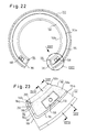
- the cage is again provided at its ends with end rings 144, which are partially ring-shaped in accordance with the circumferential extent of the cage 112. Seals are provided to prevent dirt from entering the area of the balls.
- the radial play is necessary to enable the sealing ring 146 to be adapted to the changed geometry when the shaft 178 is angularly adjusted relative to the cage 112. While in the embodiment according to FIGS. 1 to 13 the sealing ring 46 (referred to there as the cover plate) is closed in a circle and may therefore be movable in the peripheral direction without this interfering with the storage operation, according to the invention the sealing rings 146 are partially ring-shaped, ie open. There is still a need to allow the sealing rings 146 radial play in order to enable them to adapt to changed bearing geometry in the event of loss of escape between the shaft 178 and the cage 112.
- sealing rings 146 there is a need to prevent the sealing rings 146 from twisting, since in the event of a possibility of rotation, these sealing rings 146 may protrude from one or the other end face 186 of the cage (see FIG. 22) or may step behind them.
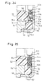
- FIGS. 23 and 24 In order to make the sealing ring 146 movable in the radial direction, but to fix it in the peripheral direction, a design is provided as shown in detail in FIGS. 23 and 24.
- Cams 188 which can also be seen in FIGS. 22 and 23, rise above the axially directed surface 184a. These cams 188 penetrate openings 190, as can be seen from FIGS. 23 and 24.
- the openings 190 have a radial oversize compared to the radial width of the cams 188, so that the sealing rings 146 still have a radial play.
- the cams 188 are only attached in the end regions of the sealing ring 146, that is to say close to the support bearings 180 of FIG. 20.
- the height of the cams 188 compared to the axially directed surface 184a of the cage 112 is greater than the axial thickness of the respective base body 146a.
- the surface 144a that is to say the inside of the pot base 144b of the cup-shaped end ring 144, lies against the end surface 188a of the respective cam 188 and is screwed to the cage there. The screwing takes place by means of a countersunk screw 192, which is screwed into the cam 188.
- peripheral fixing of the ring seals can also take place by means of projections 189 of the ring seals 146 against the end strips 184c (FIG. 23). Then the cams 188 would still be needed for fastening the end rings 144. The cams 188 could then have peripheral play in relation to the openings 190 in addition to the radial play which is still necessary.
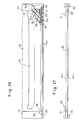
- the root part 194a is inserted in an axially extending and radially inwardly open groove 196 of the cage 112 near its respective gap-limiting surface 186.
- the grooves 196 each extend up to the axially directed surfaces 184a and are expanded peripherally in their end sections e, so that support shoulders 198 are formed (FIG. 26).
- the root parts 194a of the longitudinal sealing strips 194 have, in the axial end regions, peripherally projecting projections 200 which bear against the support shoulders 198.
- the longitudinal sealing strips 194 have extensions 202 of constant profile with root part 194a and tongue part 194b, which project beyond the projections 200 axially towards the bottom wall 144b of the end ring 144 into the ring recess 144, so that, as shown in FIG.
- the sealing ring 146 on the Extension 202 comes to rest.
- the end faces 146c pointing in the peripheral direction are adapted to the profile of the sealing strips 194. Due to the mutual abutment of the extensions 202 and the sealing rings 146 in the region of the recess 184, the space between the shaft 178 and the cage 112 is completely sealed.
- FIG. 27 shows the longitudinal sealing strip 194 before assembly. Axially outside of the projections 200, grip elements 204 are attached to the two ends of a longitudinal sealing strip 194, which, when the longitudinal sealing strips 194 are assembled, allow the sections between the projections 200 to be stretched such that the projections 200 are pushed over the shoulder surfaces 198 and onto them can be stored. After assembly, the handle elements 204 are separated outside the extensions 202, leaving the extensions 202.
- FIG. 28 shows a running plate 14, the outer surface 16 of which has already been indicated schematically in FIG. 6.
- the outer surface 16 has a central rectilinear longitudinal section f, to which an axial longitudinal section h, which is also rectilinear, is connected via transition curves g with a radius of curvature gl.
- the longitudinal section h forms an angle ⁇ of 35 angular minutes with the longitudinal section f.
- the total length of the supporting row of balls is designated i.
- the length i of the row of supporting balls is approximately 100% to approximately 200%, preferably approximately 130% to approximately 180% of the diameter of the shaft 178; the length of the central longitudinal section f is approximately 2% to approximately 15%, preferably approximately 5% to approximately 10% of the diameter of the shaft 178; the radius of curvature gl of the transition rounding g is more than approx. 100%, preferably more than approx. 150% and for example 167% to 300% of the diameter of the shaft 178.
- the angle inclination ⁇ is approx. 25 to 45 angular minutes, in the example case approx. 35 Angular minutes.
- the running plates 14 still have a certain ability to tilt or rock, but on the other hand, in normal operation, due to the straightness in the central longitudinal region f, the surface pressure is reduced to such an extent that the wear remains small compared to a surrounding bearing bore . It has also been shown that if the dimensions specified in the range of the tilting movements to be expected in the event of loss of escape between the shaft axis and the cage axis are maintained, the approach of diametrically opposed running plates 14 remains within acceptable limits and thus also the pressure which the balls bear against the shaft 178 on the one hand and exercise against the tread plates 14 on the other hand.
- the embodiment of the running plates according to FIG. 28 can be used in all embodiments of the linear ball bearing as described above and can also be used.
- running plates on their outer surface 16, as shown in FIG. 2 are rounded in accordance with the inner peripheral surface of a receiving bearing housing bore, so that a flat contact of the running plates in the region of the central longitudinal section f with the bearing housing bore is ensured.
Abstract
Description
Die Erfindung betrifft eine Linearkugelbüchse umfassend einen Käfig mit einer Käfigachse und mit einer Mehrzahl von Kugelumläufen,
wobei jeder Kugelumlauf zwei zur Käfigachse im wesentlichen parallele Geradkugelreihen, nämlich eine Tragkugelreihe und eine Rücklaufkugelreihe und zwei die beiden Geradkugelreihen verbindende Bogenkugelreihen aufweist,
wobei weiter mindestens eine Geradkugelreihe eines Kugelumlaufs nach radial aussen an einer Laufplatte anliegt, welche in eine zugehörige Ausnehmung des Käfigs eingesetzt ist und eine Aussenfläche zur Anlage an einer Innenumfangsfläche einer den Käfig aufnehmenden Lagergehäusebohrung besitzt,
wobei weiter an einer Innenfläche der Laufplatte ein Geradlaufbahnabschnitt für mindestens eine Geradkugelreihe des jeweiligen Kugelumlaufs ausgebildet ist und
wobei die jeweilige Tragkugelreihe nach radial innen einen Schlitz des Käfigs teilweise durchdringt, um an einer von dem Käfig zumindest teilweise umschlossenen Welle Anlage nehmen zu können.The invention relates to a linear ball bushing comprising a cage with a cage axis and with a plurality of ball revolutions,
wherein each ball circulation has two rows of straight balls substantially parallel to the cage axis, namely a row of supporting balls and a row of return balls and two rows of arcs connecting the two rows of straight balls,
wherein at least one row of straight balls of a recirculating ball lies radially outward on a running plate which is inserted into an associated recess in the cage and has an outer surface for bearing against an inner peripheral surface of a bearing housing bore which receives the cage,
wherein a straight track section for at least one straight ball row of the respective ball circulation is further formed on an inner surface of the running plate and
wherein the respective row of support balls partially penetrates radially inward a slot of the cage in order to be able to bear against a shaft which is at least partially enclosed by the cage.
Eine solche Linearkugelbüchse ist beispielsweise durch die GB-A-2 174 153 bekannt geworden. Bei dieser bekannten Linearkugelbüchse sind keinerlei besondere Maßnahmen zu dem Zweck dargestellt oder beschrieben, die Kugeln nach dem Einbau der Laufbahnplatten in den Käfig einzufüllen.
Bei einer solchen Linearkugelbüchse besteht das Problem des Einfüllens der Kugeln in den jeweiligen Kugelumlauf. Dieses Problem lässt sich beispielsweise so lösen, dass die Kugeln nach Einbau der Laufplatten durch nach radial auswärts offene Schlitze des Käfigs in die jeweilige Rücklaufkugelreihe eingedrückt werden. Eine andere Lösungsmöglichkeit besteht darin, dass man die Kugeln vor Einbau der jeweiligen Laufplatte in den jeweiligen Kugelumlauf einfüllt und die Laufplatte erst nachträglich anbringt.Such a linear ball bushing has become known, for example, from GB-A-2 174 153. In this known linear ball bushing, no special measures are shown or described for the purpose of filling the balls into the cage after the raceway plates have been installed.
With such a linear ball bushing there is the problem of filling the balls into the respective ball circulation. This problem can be solved, for example, by pressing the balls into the respective row of return balls through slots in the cage that are open radially outwards after the running plates have been installed. Another possible solution is to fill the balls in the respective ball circulation before installing the respective running plate and to attach the running plate only afterwards.
In der deutschen Gebrauchsmusterschrift 78 35 003 ist eine Linearkugelbüchse beschrieben, bei der sich zu beiden Seiten der die Tragkugelreihe nach radial einwärts sichernden Käfiglippen Ausnehmungen im Käfigmaterial befinden und zwar nahe einem axialen Ende der Tragkugelreihe. Durch diese Ausnehmungen werden die Lippen nachgiebig gemacht. Die Kugeln können dann mit einer automatischen Einfüllvorrichtung von innen nach aussen in die Tragkugelreihe eingedrückt werden. Da die Einführung der Kugeln vom Innenraum des Käfigs her erfolgt, dieser Innenraum aber entsprechend dem jeweiligen Wellendurchmesser begrenzt ist, muss ein kompliziertes Einfüllrohr mit mehreren Umlenkbögen verwendet werden. Durch das Auffedern der Lippen beim Einfüllen der Kugeln besteht die Gefahr, dass dort Druckstellen entstehen, die den Kugelablauf stören.The German utility model 78 35 003 describes a linear ball bushing in which there are recesses in the cage material on both sides of the cage lips which secure the row of support balls radially inwards, namely near an axial end of the row of support balls. The lips are made flexible by these recesses. The balls can then be pressed into the row of supporting balls from the inside out using an automatic filling device. Since the balls are inserted from the interior of the cage, but this interior is limited according to the respective shaft diameter, a complicated filler pipe with several deflection bends must be used. If the lips are opened when the balls are filled in, there is a risk that pressure points will appear there, which will disrupt the ball flow.
Der Erfindung liegt die Aufgabe zugrunde, bei einer Linearkugelbüchse der eingangs bezeichneten Art das Einführen der Kugeln zu erleichtern und insbesondere den Einsatz einer automatischen Einfüllvorrichtung zu ermöglichen und dabei die Gefahr einer Störung des Kugelumlaufs im Betrieb herabzusetzen oder zu vermeiden.The invention has for its object to facilitate the insertion of the balls in a linear ball bushing of the type mentioned and in particular to enable the use of an automatic filling device and thereby reduce or avoid the risk of a disturbance of the ball circulation during operation.
Zur Lösung dieser Aufgabe wird vorgeschlagen, dass die Ausnehmung des Käfigs zumindest an einem ihrer Enden und annähernd in Flucht mit einer Geradlaufbahn des Käfigs eine Füllschräge besitzt, und/oder dass die Laufplatte an ihrer Innenfläche im Bereich mindestens eines ihrer Enden in annähernder Flucht mit dem einen Geradlaufbahnabschnitt eine Füllabschrägung besitzt, wobei diese Füllschräge und/oder diese Füllabschrägung das Einfüllen von Kugeln in den einen Geradlaufbahnabschnitt dann gestatten, wenn die Laufplatte an diesem einen Ende aus der Ausnehmung ganz oder teilweise ausgehoben ist.To solve this problem, it is proposed that the recess of the cage has a filling slope at least at one of its ends and approximately in alignment with a straight track of the cage, and / or that the running plate on its inner surface in the area of at least one of its ends be in approximately alignment with the a straight track section has a filler bevel, this filler bevel and / or this filler bevel allowing balls to be filled into a straight track section when the running plate is completely or partially lifted out of the recess at this end.
Bei der erfindungsgemässen Ausbildung brauchen die Laufplatten an ihrem der jeweiligen Einfüllstelle zugekehrten Ende nur noch um ein geringes Maß ausgekippt zu werden, so dass sich die Kugeln beim Einfüllen zwangsläufig hintereinander einordnen. Der Abstand zwischen dem jeweiligen Laufbahngrund und der Laufplatte bleibt so klein, dass sich nicht zwei Kugeln übereinander schieben und sich gegenseitig verklemmen können. Damit ist sichergestellt, dass die Kugeln in der richtigen Zahl in den jeweiligen Kugelumlauf eingeführt werden und dass die Laufplatten anschliessend in die Betriebsstellung zurückgeklappt werden können.In the embodiment according to the invention, the running plates only need to be tilted out to a small extent at their end facing the respective filling point, so that the balls inevitably arrange themselves one behind the other when filling. The distance between the respective track base and the running plate remains so small that two balls cannot slide over one another and jam each other. This ensures that the correct number of balls are inserted into the respective ball circulation and that the running plates can then be folded back into the operating position.
Um eine automatische Montage der Linearkugelbüchse zu erleichtern und Fehlorientierungen des Käfigs bzw. der Laufplatten zu vermeiden, wird weiter vorgeschlagen, dass an beiden Enden der Ausnehmung Füllschrägen und/oder dass an beiden Enden der Laufplatte an deren Innenseite Füllabschrägungen vorgesehen sind.In order to facilitate automatic assembly of the linear ball bushing and to avoid misorientations of the cage or the running plates, it is further proposed that filling bevels and / or filling bevels are provided on both ends of the running plate on the inside of both sides of the recess.
Der Erfindungsgedanke ist anwendbar, gleichgültig ob an der Innenfläche der Laufplatte nur ein Geradlaufbahnabschnitt oder eine geschlossene Laufbahn ausgebildet ist.The idea of the invention is applicable, regardless of whether only a straight track section or a closed track is formed on the inner surface of the running plate.
Wenn an der Innenfläche der Laufplatte nur ein tragender Laufbahnabschnitt für die Tragkugelreihe angebracht ist, so wird die Füllschräge und/oder die Füllabschrägung in Flucht mit dieser tragende Geradlaufbahn bzw. mit diesem tragenden Geradlaufbahnabschnitt angebracht.If only one supporting track section for the row of supporting balls is attached to the inner surface of the running plate, the filling slope and / or the filling chamfer is applied in alignment with this supporting straight track or with this supporting straight track section.
Wenn andererseits an der Innenfläche der Laufbahnplatte eine geschlossene Laufbahn ausgebildet ist mit einem tragenden Geradlaufbahnabschnitt für die Tragkugelreihe, mit einem Geradlaufbahnabschnitt für die Rücklaufkugelreihe und mit zwei die beiden Geradlaufbahnabschnitte verbindenden Bogenlaufbahnabschnitten, so empfiehlt es sich, dass die Füllschräge und/oder die Füllabschrägung in axialer Flucht mit der rückführenden Geradlaufbahn bzw. mit dem rückführenden Geradlaufbahnabschnitt angeordnet sind, weil in dem rückführenden Geradlaufbahnabschnitt die Kugeln in der Regel grössere Führungsfreiheit besitzen und insbesondere weil der rückführende Geradlaufbahnabschnitt, bezogen auf die Achse des Käfigs, radial weiter nach aussen gelegt ist, so dass mit einem geringeren Auskippwinkel der Laufplatte bereits eine Füllung möglich ist.If, on the other hand, a closed track is formed on the inner surface of the raceway plate with a load-bearing straight track section for the supporting ball row, with a straight track section for the return ball row and with two arc track sections connecting the two straight track sections, then it is recommended that the fill slope and / or the fill bevel be in the axial direction Escape with the returning straight track or with the returning straight track section are arranged because in the returning straight track section, the balls generally have greater freedom of guidance and in particular because the returning straight track section, based on the axis of the cage, is placed radially further outwards, so that a filling is already possible with a lower tipping angle of the running plate.
Aus fertigungstechnischen Gründen bei der Herstellung der Laufplatten empfiehlt es sich, dass geradlinige Verlängerungen der Geradlaufbahnabschnitte bis an die Enden der Laufplatte im wesentlichen profilkonstant fortgesetzt sind unter Verschneidung mit den Bogenlaufbahnabschnitten. Diese geradlinigen Verlängerungen des jeweils zu füllenden Geradlaufbahnabschitts bringen in Verbindung mit der Füllschräge bzw. der Füllabschrägung eine weitere Erleichterung des Einfüllens der Kugeln.For technical reasons in the manufacture of the running plates, it is recommended that straight-line extensions of the straight running track sections to the ends of the running board are continued essentially in a constant profile, intersecting with the curved running track sections. These straight-line extensions of the straight track section to be filled in each case, in conjunction with the filling slope or the filling slope, further facilitate the filling of the balls.
Die Erfindung betrifft weiter ein Verfahren zum Einfüllen der Kugeln in einen Kugelumlauf einer Linearkugelbüchse, wobei die Linearkugelbüchse nach einem der Ansprüche 1 bis 8 ausgebildet ist,The invention further relates to a method for filling the balls into a ball circulation of a linear ball bushing, the linear ball bushing being designed according to one of
Dabei wird zum Füllen in der Weise vorgegangen, dass die Kugeln bei einendig aus der Ausnehmung ausgekippter Laufplatte über eine Füllschräge am offenen Ende der Ausnehmung und/oder eine Füllabschrägung am ausgekippten Ende der Laufplatte hinweg in jeweils eine Geradlaufbahn eingeführt werden und dass nach Vervollständigung der Kugeln des Kugelumlaufs die Laufplatte in Betriebsstellung zurückgekippt und in der Betriebsstellung gesichert wird.For filling, the procedure is such that the balls are inserted into a straight track in each case with a running plate tilted out of the recess at one end via a filling slope at the open end of the recess and / or a filling bevel at the tilted end of the running plate, and that after the balls have been completed of the ball recirculation, the running plate is tipped back into the operating position and secured in the operating position.
Es wird darauf hingewiesen, dass die Füllschrägen und die Füllabschrägungen derart bemessen sind, dass der Kugelablauf nicht gestört wird, d.h. dass alle notwendigen Kugelführungsflächen am Käfig sowohl als auch in der Laufplatte erhalten bleiben.It is pointed out that the filling bevels and the filling bevels are dimensioned such that the ball flow is not disturbed, i.e. that all necessary ball guide surfaces on the cage as well as in the running plate are retained.
Ein besonderer Vorteil liegt darin, dass während des Kugelfüllvorgangs das von der Einfüllstelle abgelegene Ende der Laufplatte annähernd in Betriebsstellung innerhalb der Ausnehmung gehalten werden kann. Dies erleichtert es, die jeweilige Laufplatte bei dem Füllvorgang in der richtigen Lage zu halten.A particular advantage is that, during the ball filling process, the end of the running plate remote from the filling point can be held approximately in the operating position within the recess. This makes it easier to hold the respective running plate in the correct position during the filling process.
Wenn die Laufplatten in dem Käfig betriebsmässig durch topfförmige Endringe gehalten sind, so kann man für das Einfüllen der Kugeln zunächst nur einen topfförmigen Endring anbringen, um die Laufplatten zunächst nur an ihren von der Füllstelle abgelegenen Enden festzuhalten und in den füllstellennahen Enden auskippen zu können. Nach dem Einfüllen der Kugeln wird dann der den Eingriffstellen nahe topfförmige Endring angebracht, nachdem vorher die Laufplatten in ihre Betriebsstellung zurückgekippt worden sind.If the running plates are held in the cage by pot-shaped end rings, you can only attach a cup-shaped end ring to fill the balls in order to first hold the running plates only at their ends remote from the filling point and to tip them out at the ends near the filling point. After the balls have been filled in, the cup-shaped end ring close to the engagement points is then attached after the running plates have previously been tilted back into their operating position.
Die beiliegenden Figuren erläutern die Erfindung anhand eines Ausführungsbeispiels. Es stellen dar: zur Darstellung des technischen Gesamtzusammenhangs
Figur 1 einen Längsschnitt durch eine erfindingsgemässe Linearkugelbüchse;Figur 2 einen Querschnitt nach Linie II - II derFigur 1;Figur 3 eine Ansicht der Innenseite einer Laufplatte;Figur 4 eine Endansicht einer Laufplatte gemässFigur 3;Figur 5 einen Schnitt nach Linie V - V derFigur 3;Figur 6 eine Vergrösserung des Bereichs VI derFigur 5 in einem Schnitt entsprechend demjenigen derFigur 5;Figur 7 eine Vergrösserung eines Endabschnitts der Laufplatte gemässFigur 3;- Figur 8 einen Schnitt nach Linie VIII - VIII der
Figur 7; Figur 9 einen Schnitt nach Linie IX - IX derFigur 7;Figur 10 einen Schnitt nach Linie X - X der Figur 8;- Figur 11 einen Schnitt nach Linie XI - XI der Figur 8;
Figur 12 einen Niveauplan mit tabellarischer Erfassung der Sohlenniveaus der Laufbahn in einem Endabschnitt der Laufplatte gemässFigur 7; zur Darstellung der eigentlichen Erfindung- Figur 13 einen Querschnitt durch einen Käfig entlang Linie II - II der
Figur 1, jedoch nach Entfernung der Laufplatten und Kugeln; Figur 14 ein Detail zu Figur 13 in Vergrösserung;- Figur 15 eine Teilansicht des Käfigs in Pfeilrichtung XV der Figur 13;
Figur 16 einen Längsschnitt durch den Käfig nach Linie XVI - XVI der Figur 13;- Figur 17 einen Längsschnitt nach Linie XVII - XVII der Figur 13;
Figur 18 eine Teilansicht einer Laufplatteentsprechend Figur 7, jedoch mit einer Endabschrägung;- Figur 19 einen Schnitt nach Linie XIX - XIX der Figur 15 beim Einfüllen von Kugeln;
und wiederum zur Darstellung des Gesamtzusammenhangs Figur 20 einen Schnitt durch ein Linearkugellager gemässFigur 1, jedoch insofern abgewandelt, als der Käfig zur Aufnahme einer Unterstützung für die Welle teilringförmig ausgebildet ist;- Figur 21 ein Detail entsprechend der Stelle XXI der
Figur 20 in Vergrösserung; Figur 22 eine Endansicht eines Linearkugellagers gemässFigur 20, wobei ein ebenfalls teilringförmiger , topfringförmiger Endring abgenommen ist;- Figur 23 eine Vergrösserung des Details XXIII der
Figur 22; Figur 24 einen Schnitt nach Linie XXIV - XXIV der Figur 23;- Figur 25 einen Schnitt nach Linie XXV - XXV der Figur 23;
Figur 26 eine Teilansicht in Richtung des Pfeiles XXVI derFigur 22, teilweise geschnitten;- Figur 27 eine Längsdichtungsleiste als Detail zur
Figur 26 und Figur 28 eine Darstellung der Laufplatte entsprechendFigur 6.
- FIG. 1 shows a longitudinal section through a linear ball bushing according to the invention;
- Figure 2 shows a cross section along line II - II of Figure 1;
- Figure 3 is a view of the inside of a running plate;
- FIG. 4 shows an end view of a running plate according to FIG. 3;
- 5 shows a section along line V - V of Figure 3;
- FIG. 6 shows an enlargement of area VI of FIG. 5 in a section corresponding to that of FIG. 5;
- FIG. 7 shows an enlargement of an end section of the running plate according to FIG. 3;
- Figure 8 is a section along line VIII - VIII of Figure 7;
- 9 shows a section along line IX-IX of FIG. 7;
- Figure 10 shows a section along line X - X of Figure 8;
- FIG. 11 shows a section along line XI-XI of FIG. 8;
- FIG. 12 shows a level plan with tabular recording of the sole levels of the running track in an end section of the running plate according to FIG. 7; to illustrate the actual invention
- FIG. 13 shows a cross section through a cage along line II-II of FIG. 1, but after removal of the running plates and balls;
- FIG. 14 shows a detail of FIG. 13 on an enlarged scale;
- Figure 15 is a partial view of the cage in the direction of arrow XV of Figure 13;
- 16 shows a longitudinal section through the cage along line XVI - XVI of FIG. 13;
- 17 shows a longitudinal section along line XVII - XVII of FIG. 13;
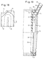
- FIG. 18 shows a partial view of a running plate corresponding to FIG. 7, but with an end bevel;
- FIG. 19 shows a section along line XIX-XIX of FIG. 15 when balls are filled;
and again to show the overall context - FIG. 20 shows a section through a linear ball bearing according to FIG. 1, but modified to the extent that the cage is designed in the form of a partial ring to accommodate a support for the shaft;
- FIG. 21 shows a detail corresponding to position XXI of FIG. 20, on an enlarged scale;
- FIG. 22 shows an end view of a linear ball bearing according to FIG. 20, with a likewise part-ring-shaped, cup-ring-shaped end ring being removed;
- FIG. 23 shows an enlargement of detail XXIII of FIG. 22;
- FIG. 24 shows a section along line XXIV-XXIV of FIG. 23;
- 25 shows a section along line XXV - XXV of FIG. 23;
- Figure 26 is a partial view in the direction of arrow XXVI of Figure 22, partially in section;
- Figure 27 is a longitudinal sealing strip as a detail of Figure 26 and
- FIG. 28 shows the running plate corresponding to FIG. 6.
In Figur 1 und 2 ist eine Linearkugelbüchse ganz allgemein mit 10 bezeichnet. Sie umfaßt einen Käfig 12 aus hartelastischem Kunststoff. In diesen Käfig 12 sind Laufplatten 14 eingesetzt, welche jeweils eine Außenumfangsfläche 16 zur Anlage an einer die Linearkugelbüchse 10 aufnehmenden Lagergehäusebohrung und eine Innenumfangsfläche 18 besitzen. Die Laufplatten 14 bestehen aus einem harten Werkstoff, insbesondere gehärtetem Stahl. Durch den Käfig 12 und die Laufplatten 14 ist jeweils eine Führung für einen Kugelumlauf gebildet. Die Kugeln sind mit 20 bezeichnet. Jeder Kugelumlauf bildet eine Tragkugelreihe 22 und eine Rücklaufkugelreihe 24. Die Tragkugelreihen 22 ragen durch Schlitze 26 des Käfigs 12 hindurch nach radial innen zur Anlage an einer nicht dargestellten Welle. Die Rücklaufkugelreihen 24 sind nach radial innen durch den Käfig 12 gestützt. Beide Geradkugelreihen 22 und 24 liegen an der Innenumfangsfläche 18 der jeweiligen Laufplatte 14 an. Die Tragkugelreihe 22 und die Rücklaufkugelreihe 24 sind jeweils durch Bogenkugelreihen 28 verbunden. Die Laufplatten 14 sind in dem Käfig 12 formschlüssig gehalten, jedoch mit einem gewissen Bewegungsspiel.1 and 2, a linear ball bushing is generally designated 10. It comprises a
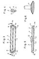
In Figuren 3, 4 und 5 ist eine Laufplatte 14 im einzelnen dargestellt. Diese Laufplatte 14 ist auf der Basis eines Profilstabs hergestellt, dessen Profil aus Figur 4 ersichtlich ist. Die Laufplatte 14 weist einen tragenden Geradlaufbahnabschnitt 30 auf, welcher gegenüber der Außenumfangsfläche 16 ein erstes höheres Niveau besitzt und einen rückführenden Geradlaufbahnabschnitt 32, welcher gegenüber der Außenumfangsfläche 16 ein niedrigeres Niveau besitzt. Der tragende Laufbahnabschnitt 30 dient zur Aufnahme der Tragkugelreihe 22 und der Geradlaufbahnabschnitt 32 zur Aufnahme der Rücklaufkugelreihe 24. Die beiden Geradlaufbahnabschnitte 30 und 32 sind durch Bogenlaufbahnabschnitte 36 miteinander verbunden. Die Geradlaufbahnabschnitte 30 und 32 erstrecken sich jedoch mit den Endabschnitten 30a bzw. 32a im wesentlichen profilkonstant bis an die Enden der Laufplatte 14. Zwischen den Geradlaufbahnabschnitten 30 und 32 liegt eine Mittelrippe 38. Die Mittelrippe 38 setzt sich mit Endabschnitten 38a bis an die Enden der Laufplatte 14 profilkonstant fort und ist durch die Bogenlaufbahnabschnitte 36 lediglich unterbrochen. An ihrer Aussenumfangsfläche 16 ist die Laufbahnplatte, wie in Figur 6 dargestellt, gekrümmt, so daß sie schaukelnd an der Innenumfangsfläche einer Lagergehäusebohrung zur Anlage kommt. Wie aus Figur 4 ersichtlich sind die Geradlaufbahnabschnitte 30 und 32 gerundet mit einem Krümmungsradius, der gleich oder wenig größer ist als der Radius der Kugeln 20.A running
In Figur 5 erkennt man an den Enden der Laufplatte Ausdrehungen 40 und 42. Die Ausdrehungen 40 sind zur Aufnahme von topfförmigen Endringen 44 (Figur 1) bestimmt, welche die Laufplatte 14 und Abschlußscheiben 46 am Käfig 12 sichern. Die Eindrehungen 42 sind dazu bestimmt, Sicherungsringe zur axialen Sicherung der Kugelbüchse in einer Aufnahmebohrung aufzunehmen.In FIG. 5, one can see
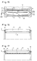
Nähere Einzelheiten über die Ausbildung der Laufbahnen ergeben sich aus den Figuren 7 bis 11. Die Bogenlaufbahnabschnitte 36 erstrecken sich über annähernd 180° und sind annähernd kreisförmig gekrümmt. Der Niveauabfall von dem Geradlaufbahnabschnitt 30 zu dem Geradlaufbahnabschnitt 32 beginnt bereits in einem Endabschnitt a des Geradlaufbahnabschnitts 30. Dadurch liegt die Sohle des Bogenlaufbahnabschnitts 36 im Bereich der Verschneidung mit dem Geradlaufbahnabschnitt 30 tiefer als eine gedachte Fortsetzung der Sohle des Geradlaufbahnabschnitts 30 ,und eine Seitenführung der Kugeln ist auch in diesem Verschneidungsbereich gewährleistet Das Niveaugefälle im Endabschnitt a ist durch die Winkelangabe 2° in Figur 8 dargestellt. Das Niveaugefälle im unmittelbar anschließenden Bereich des Bogenlaufbahnabschnitts 36 beträgt, wie in Figur 8 ebenfalls dargestellt, ca. 5°. Es treten keine Niveausprünge auf. Die Gefällsübergänge sind abgerundet Die Längsausdehnung des Endabschnitts a ist auch nach dem Schleifen so groß, daß die belasteten Kugeln vor Einlauf in den Bogenlaufbahnabschnitt 36 kontinuierlich entlastet werden können. Dies gilt analog auch für die in die Lastzone eintretenden Kugeln. Durch diese Maßnahme ist ein gleichmäßiger und ruckfreier Ablauf gewährleistet. An der Stelle ⑥ in Figur 7 besitzt die Bogenlaufbahn 36 ein Niveauminimum, welches unter dem Niveau der rückführenden Geradlaufbahn 32 liegt. Im Endabschnitt b des rückführenden Geradlaufbahnabschnitts 32 findet ein langsamer Niveauanstieg statt. Es treten keine Niveausprünge auf. Die Gefällsübergänge sind verrundet. Das Niveauminimum ⑥ ist auch nach dem Schleifen des rückführenden Geradlaufbahnabschnitts 32 noch vorhanden. Die Gefällsstrecken a und b der Geradlaufbannabschnitte 30, 32 sind zusammen mit den Bogenlaufbahnabschnitten 36 geprägt. Die Verjüngung der Rippenbreite der Mittelrippe 38 im Bereich der Endabschnitte a und b ergibt einen trichterförmigen Übergang des Bogenlaufbahnabschnitts 36 in die Geradlaufbahnabschnitte 30 und 32.Further details on the formation of the raceways can be found in FIGS. 7 to 11. The
In Figur 12 sind mit ① bis ⑦ verschiedene Meßpunkte bezeichnet, die teilweise auch in Figur 7 eingetragen wurden, um die Relationen zwischen Figur 7 und 12 klar zu machen. Diesen Meßpunkten sind nach der Tabelle der Figur 12 verschiedene Niveauwerte beispielshalber zugeordnet. Die Niveauwerte bezeichnen die relative Niveauhöhe in Millimeter jeweils auf der Sohle der Laufbahn gegenüber dem Sohlenniveau des tragenden Laufbahnabschnitts 30, welches mit Null bewertet ist.In FIG. 12, ① to bezeichnet denote various measuring points, some of which have also been entered in FIG. 7, in order to make the relationships between FIGS. 7 and 12 clear. According to the table in FIG. 12, these measuring points are assigned various level values for the sake of example. The level values denote the relative level height in millimeters in each case on the sole of the track compared to the level of the base of the load-
Man erkennt aus der zweiten Spalte der Tabelle ohne weiteres, daß im Bereich ⑤ bis ⑥ ein Niveauminimum vorliegt, und daß von diesem Niveauminimum aus ein Anstieg des Niveaus bis auf die Niveauhöhe der Sohle des rückführenden Geradlaufbahnabschnitts 32 stattfindet. Der Wiederanstieg ⑥ bis ⑦ liegt im wesentlichen in der Rücklaufgeraden des rückführenden Geradlaufbahnabschnitts 32. Den einzelnen Punkten ① bis ⑦ zugeordneten Ortskoordinaten sind durch die Winkelwerte in der Figur 12 bezeichnet. Die Figur 12 vermittelt durch die Längenangabe 39,5 mm auch eine Größenordnungsvorstellung von der Länge der Kugelbüchse. Ergänzend hierzu sei bemerkt, daß der Außendurchmesser des Käfigs 12 im Beispielsfall 40 mm beträgt, daß insgesamt 10 Laufplatten vorgesehen sind, wie in Figur 2 dargestellt, daß die periphere Erstreckung einer Laufplatte 9,7 mm beträgt, und daß der Kugeldurchmesser 3,969 mm beträgt. Schließlich beträgt der Krümmungsradius der Laufbahn an der Sohle gemessen (strichpunktierte Linie in Figur 12) 2,04 mm. In der Tabelle sind schließlich in der vierten Spalte die jeweiligen Radien der Laufbahnabschnitte in Millimetern aufgezeichnet. Man erkennt, daß diese Radien wenig größer sind als der Kugelradius, so daß die Kugeln seitlich geführt sind. Aus der Figur 12 und der Tabelle erkennt man, daß im Bereich ① bis ④ eine Seitenführung gewährleistet ist; diese Seitenführung ist im Scheitelbereich ④ durch den Fortsatz 38a der Rippe 38 ergänzt. Auch in dem relativ unkritischen Bereich ④ bis ⑦ ist noch eine gewisse Seitenführung der Kugeln durch die Laufplatte gewährleistet, wie durch die Verschneidungslinie 50 angedeutet. Es sei noch einmal erwähnt, daß die einzelnen Gefällsstrecken von ① bis ⑦ im wesentlichen stetig ineinander übergehen.It can easily be seen from the second column of the table that there is a level minimum in the
Die Führung der Kugeln ist durch den Käfig 12 ergänzt. Die Führungsflächen in dem Käfig 12 sind mit hoher Präzision so gefertigt, daß sie an die Führungsflächen der Laufplatten versatzlos anschliessen.The guidance of the balls is supplemented by the
Die in den Figuren 3 und 7 erkennbaren Aussparungen 52 dienen zum Teil der Materialaufnahme beim Prägen der Bogenlaufbahnabschnitte 36; anders ausgedrückt: Beim Prägen werden die Laufplatten 14 mit vorher gebildeten Aussparungen in Prägeformen eingelegt, welche der Außenumfangsfläche 16 und den Endflächen anliegen, jedoch im Bereich der Aussparungen 52 so viel Luft lassen, daß das beim Prägen verdrängte Material einfließen kann und dabei die Geometrie der Aussparungen gemäß Figur 7 entsteht.The
In Figur 13 ist der Käfig gemäss Figur 2 nach Entnahme der Laufplatten 14 und der Kugeln 20 dargestellt. Man erkennt dort die Ausnehmungen 60 für die Aufnahme der Laufplatten 14 der Figur 2. Man erkennt weiter die Schlitze 26, welche den Kugeln der Tragkugelreihe (22) teilweisen Durchtritt gewähren und man erkennt die Laufbahn 62 für die Rücklaufkugelreihe 24 der Figur 2. Dies alles ist in Vergrösserung auch in Figur 14 dargestellt. Man erkennt weiter aus den Figuren 14 und 15, dass an den Enden der Ausnehmungen 60, und zwar angrenzend an die Endflächen 64 der Ausnehmungen 60 annähernd in Flucht mit den Laufbahnen 62 rinnenförmige Füllschrägen 66 angeordnet sind, deren Bedeutung insbesondere aus Figur 19 zu ersehen ist. Dort wird zum Einfüllen der Kugeln 20 eines Kugelumlaufs ein Füllrohr 68 angesetzt, so dass es annähernd in Fortsetzung der jeweiligen Füllschräge 66 steht. Dabei ist der obere topfförmige Endring 44 abgenommen, während der untere topfförmige Endring 44 seine Sicherungsposition bezüglich der Laufplatten 14 einnimmt. Da der obere Endring 44 fehlt, kann die Laufplatte 14, wie aus Figur 19 zu ersehen, schräggestellt werden, so dass sie im Bereich der Einlaufschräge 66 den Kugeln 20 Einlass gewährt. Das Schrägstellen der Laufplatten 14 ist möglich, da die Längsbegrenzungsflächen 70, 72 der Ausnehmung 60 annähernd zueinander parallel sind, oder aber das Kunststoffmaterial des Käfigs 12 derart elastisch ist, dass ein Ausstellen der Laufplatte 14 unter Zwang möglich ist.FIG. 13 shows the cage according to FIG. 2 after removal of the running
Das Einfüllen der Kugeln 20 in die Laufbahn 62 der Rücklaufkugelreihe wird noch dadurch erleichtert, dass an der Innenseite der Laufplatte 14, wie aus Figuren 18 und 19 ersichtlich, eine Abschrägung 74 angebracht ist.The filling of the
Es ist zu bemerken, dass die Art des Einfüllens unter Verwendung der Einfüllschräge 66 und der Abschrägung 74 nicht daran gebunden ist, das an der Laufplatte 14 die beiden Geradlaufbahnabschnitte 30,32 und die Bogenlaufbahnabschnitte 36 angebracht sind. Die Art des Einfüllens wäre vielmehr auch dann denkbar, wenn die Laufplatten 14 auf die Breite der Geradlaufbahnabschnitte 30 der Tragkugelreihen beschränkt wären. In diesem Fall müßten nur die Einfüllschrägen 66 und die Abschrägungen 74 in Flucht mit dem jeweiligen Geradlaufbahnabschnitt 30 einer tragenden Kugelreihe angebracht werden.It should be noted that the type of filling using the filling
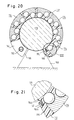
In Figur 20 erkennt man ein Linearkugellager, bei dem die Welle 178 durch Ständer 180 unterstützt und der Käfig 112 teilringförmig ausgebildet ist. Der Käfig ist an seinen Enden wieder mit Endringen 144 versehen, welche entsprechend der Umfangserstreckung des Käfigs 112 teilringförmig ausgebildet sind. Zur Verhinderung des Eindringens von Schmutz in den Bereich der Kugeln sind Dichtungen vorgesehen.A linear ball bearing can be seen in FIG. 20, in which the
In Figur 1 war auf die Abschlußscheiben 46 hingewiesen worden. Dies sind dort die notwendigen Ringdichtungen, die am Käfig durch Endringe 44 gehalten sind und mit einer Dichtlippe an der dort nicht eingezeichneten Welle zur Anlage kommen. Dieser Dichtringe bedarf es auch bei der nunmehr diskutierten Ausführungsform nach Figur 20, und man erkennt diese Dichtringe in den Figuren 22 bis 25, wo sie mit 146 bezeichnet sind und sich zusammensetzen aus einem jeweiligen Grundkörper 146a und einer Dichtlippe 146b. Die Dichtlippe 146b ist auch hier wieder zur Anlage an der Welle 178 der Figur 20 bestimmt. Der Grundkörper 146a des Dichtrings 146 ist dabei, wie insbesondere aus Figuren 23, 24 und 25 zu ersehen, in einer Ringausnehmung 184 einer Endfläche 185 des Käfigs 112 aufgenommen, welche durch eine axial gerichtete Fläche 184a und eine radial einwärts gerichtete Fläche 184b definiert und an ihren Enden durch Endleisten 184c begrenzt ist. Der Grundkörper 146a liegt mit axialem Spiel zwischen der axial gerichteten Fläche 184a des Käfigs 112 und einer axial gerichteten Fläche 144a des auf der Endfläche 185 aufliegenden Endrings 144. Das Übermaß der Ausnehmung 184 gegenüber dem Durchmesser des Grundkörpers 146a (Figur 25) gewährt dem Grundkörper 146a radiales Spiel innerhalb der Ausnehmung 184. Dieses radiale Spiel besteht auch bei der Ausführungsform nach Figur 1, ist auch dort von wesentlicher Bedeutung, ist aber dort bisher nicht erwähnt worden. Das radiale Spiel ist notwendig, um bei einer Winkelverstellung der Welle 178 gegenüber dem Käfig 112 eine Anpassung des Dichtungsrings 146 an die veränderte Geometrie zu ermöglichen. Während nun bei der Ausführungsform nach den Figuren 1 bis 13 der Dichtungsring 46 (dort als Abschlussscheibe bezeichnet) kreisförmig geschlossen ist und deshalb in peripherer Richtung beweglich sein darf, ohne dass dies den Lagerbetrieb stört, sind erfindungsgemäss die Dichtungsringe 146 teilringförmig d.h. offen. Es besteht nach wie vor die Notwendigkeit, den Dichtungsringen 146 radiales Spiel zu gestatten, um ihre Anpassung an veränderte Lagergeometrie bei Fluchtverlust zwischen Welle 178 und Käfig 112 zu ermöglichen. Es besteht aber gleichzeitig die Notwendigkeit, eine Verdrehung der Dichtungsringe 146 zu vermeiden, da diese Dichtungsringe 146 im Fall einer Verdrehungsmöglichkeit über die eine oder andere Endfläche 186 des Käfigs (siehe Figur 22) hervortreten bzw. hinter diese zurücktreten könnten.In Figure 1, the
Um den Dichtungsring 146 in radialer Richtung beweglich zu lassen, ihn in peripherer Richtung aber festzulegen, ist eine Ausbildung vorgesehen, wie sie in Figuren 23 u.24 im Detail dargestellt ist. Über der axialgerichteten Fläche 184a erheben sich Nocken 188, die auch in Figuren 22 und 23 erkennbar sind. Diese Nocken 188 durchsetzen Durchbrechungen 190, wie aus Figuren 23 und 24 zu ersehen. Dabei haben die Durchbrechungen 190 ein radiales Übermaß gegenüber der Radialbreite der Nocken 188, so dass die Dichtungsringe 146 nach wie vor ein radiales Spiel besitzen. Dabei ist zu beachten, dass gemäss Figur 22 die Nocken 188 lediglich in den Endbereichen des Dichtungsrings 146, also nahe den Stützlagern 180 der Figur 20, angebracht sind. Weiter ist zu beachten, dass die Höhe der Nocken 188 gegenüber der axial gerichteten Fläche 184a des Käfigs 112 grösser ist als die axiale Stärke des jeweiligen Grundkörpers 146a. Die Fläche 144a, also die Innenseite des Topfbodens 144b des topfförmigen Endrings 144 liegt gegen die Endfläche 188a des jeweiligen Nockens 188 an und ist dort mit dem Käfig verschraubt. Die Verschraubung erfolgt mittels einer Senkschraube 192, die in den Nocken 188 eingeschraubt ist. Wegen des Übermaßes der axialen Höhe des Nockens 188 gegenüber der axialen Dicke des Grundkörpers 146 wird auch bei straffem Anziehen der Senkschraube 192 der Grundkörper 144a nicht zwischen den Flächen 184a und 144a eingeklemmt. Auch insoweit bleibt also das radiale Spiel des Dichtungsrings 146 erhalten. Gemäß Figur 24 läßt sich auch gut erkennen, daß die Ringwand 144c in die Ausdrehungen 140 der Laufplatten 114 eingreift und an der angeschrägten Außenumfangsfläche 187 des Käfigs 112 anliegt, so daß die Laufplatten 114 in dem Käfig axial und radial gehalten sind. Es ist zu bemerken, daß die periphere Festlegung der Ringdichtungen auch durch Vorsprünge 189 der Ringdichtungen 146 gegen die Endleisten 184c (Figur 23) erfolgen kann. Dann bräuchte man die Nocken 188 trotzdem zur Befestigung der Endringe 144. Die Nocken 188 könnten dann aber peripheres Spiel gegenüber den Durchbrechungen 190 neben dem weiterhin notwendigen Radialspiel besitzen.In order to make the
Mit den Ringdichtungen 146 allein ist das Dichtungsproblem noch nicht vollständig gelöst. Wie aus den Figuren 20 bis 23 sowie 26 und 27 ersichtlich, sind im Bereich der Spaltbegrenzungsflächen 186 in dem Käfig 112 auch Längsdichtungsleisten 194 mit einem Wurzelteil 194a und einem an der Welle 178 anliegenden Zungenteil 194b vorgesehen.The sealing problem alone is not yet completely solved with the ring seals 146. As can be seen from FIGS. 20 to 23 as well as 26 and 27, longitudinal sealing strips 194 with a
Der Wurzelteil 194a ist in einer axial verlaufenden und radial einwärts offenen Nut 196 des Käfigs 112 nahe dessen jeweiliger Spaltbegrenzungsfläche 186 eingesetzt. Die Nuten 196 erstrecken sich jeweils bis zu den axial gerichteten Flächen 184a und sind in ihren Endabschnitten e peripher erweitert, so daß Stützschultern 198 gebildet sind (Figur 26). Die Wurzelteile 194a der Längsdichtungsleisten 194 weisen in den axialen Endbereichen peripher vorspringende Vorsprünge 200 auf, die sich gegen die Stützschultern 198 anlegen. Die Längsdichtungsleisten 194 besitzen Fortsätze 202 gleichbleibenden Profils mit Wurzelteil 194a und Zungenteil 194b, welche über die Vorsprünge 200 hinaus axial in Richtung auf die Bodenwand 144b des Endrings 144 in die Ringausnehmung 144 hinein vorstehen, so daß, wie in Figur 23 dargestellt, der Dichtungsring 146 an dem Fortsatz 202 zur Anlage kommt. Die in peripherer Richtung weisenden Endflächen 146c sind an das Profil der Dichtleisten 194 angepaßt. Durch das gegenseitige Anliegen der Fortsätze 202 und der Dichtungsringe 146 im Bereich der Ausnehmung 184 ist der Zwischenraum zwischen der Welle 178 und dem Käfig 112 vollständig abgedichtet.The
Die Figur 27 lässt die Längsdichtungsleiste 194 vor der Montage erkennen. Axial ausserhalb der Vorsprünge 200 sind an den beiden Enden einer Längsdichtungsleiste 194 Griffelemente 204 angebracht, die es bei der Montage der Längsdichtungsleisten 194 ermöglichen, deren zwischen den Vorsprüngen 200 gelegene Abschnitte so zu dehnen, dass die Vorsprünge 200 über die Schulterflächen 198 vorgeschoben und auf diesen aufgelagert werden können. Nach erfolgter Montage werden die Griffelemente 204 ausserhalb der Fortsätze 202 unter Belassung der Fortsätze 202 abgetrennt.FIG. 27 shows the
In Figur 28 erkennt man eine Laufplatte 14 wieder, deren Aussenfläche 16 in Figur 6 bereits schematisch angedeutet worden ist. Die Aussenfläche 16 weist einen mittleren geradlinig verlaufenden Längsabschnitt f auf, an den sich über Übergangsrundungen g mit einem Krümmungsradius gl jeweils ein axialer Längsabschnitt h anschliesst, der ebenfalls geradlinig ist. Der Längsabschnitt h schliesst mit dem Längsabschnitt f einen Winkel α von 35 Winkelminuten ein. Die Gesamtlänge der tragenden Kugelreihe ist mit i bezeichnet. Bezüglich der Grössenverhältnisse gilt folgendes:
Die Länge i der Tragkugelreihe beträgt ca. 100 % bis ca. 200 %, vorzugsweise ca. 130 % bis ca. 180 % des Durchmessers der Welle 178; die Länge des mittleren Längsabschnitts f beträgt ca. 2 % bis ca. 15 %, vorzugsweise ca. 5 % bis ca. 10 % des Durchmessers der Welle 178; der Krümmungsradius gl der Übergangsrundung g beträgt mehr als ca. 100 %, vorzugsweise mehr als ca. 150 % und beispielsweise 167 % bis 300 % des Durchmessers der Welle 178. Die Winkelneigung α beträgt ca. 25 bis 45 Winkelminuten, im Beispielsfall ca. 35 Winkelminuten.FIG. 28 shows a running
The length i of the row of supporting balls is approximately 100% to approximately 200%, preferably approximately 130% to approximately 180% of the diameter of the
Es hat sich gezeigt, dass bei Einhaltung der genannten Maße noch eine gewisse Kipp- oder Schaukelfähigkeit der Laufplatten 14 gewährleistet ist, andererseits aber im Normalbetrieb durch die Geradlinigkeit im mittleren Längsbereich f die Flächenpressung gegenüber einer umschliessenden Lagerbohrung soweit reduziert ist, dass der Verschleiß klein bleibt. Es hat sich weiter gezeigt, dass bei Einhaltung der angegebenen Maße im Bereich der bei Fluchtverlust zwischen Wellenachse und Käfigachse zu erwartenden Kippbewegungen die Annäherung diametral einander gegenüberliegender Laufplatten 14 innerhalb akzeptabler Grenzen bleibt und damit auch der Druck, den die Kugeln gegen die Welle 178 einerseits und gegen die Laufplatten 14 andererseits ausüben. Die Ausführungsform der Laufplatten nach Figur 28 ist bei allen Ausführungsformen des Linearkugellagers wie vorstehend beschrieben und darüber hinaus anwendbar.It has been shown that, provided that the dimensions mentioned are maintained, the running
Es ist zu beachten, dass die Laufplatten an ihrer Aussenfläche 16, wie in Figur 2 dargestellt, entsprechend der Innenumfangsfläche einer aufnehmenden Lagergehäusebohrung gerundet sind, so dass eine flächige Anlage der Laufplatten im Bereich des mittleren Längsabschnitts f an der Lagergehäusebohrung gewährleistet ist.It should be noted that the running plates on their
Claims (11)
- A linear ball bearing (10) comprising a cage (12) with a cage axis and a plurality of recirculating ball assemblies,
each recirculating ball assembly comprises, substantally parallel with the cage axis, two parallel straight rows of balls (22, 24), namely a row (22) of load bearing balls and a row (24) of returning balls and, connecting the two straight rows of balls (22, 24), two curved rows of balls (28),
and furthermore in which at least one straight row of balls (22, 24) in a recirculating ball assembly bears radially outwardly against a race plate (14) rich is inserted into an associated recess in the cage (12) and has an outer surface (16) to bear on an inner peripheral surface of a bearing housing bore which accommodates the cage (12),
and in which furthermore a straight track portion (30, 32) for at least one straight row of balls (22, 24) of the relevant recirculating ball assembly is constructed on an inner surface (18) of the race plate (14), and
in which the relevant row (22) of load bearing balls, in a radially inward direction, partially penetrating a slot (26) in the cage (12) in order to be able to bear on a shaft rich is at least partially surrounded by the cage (12),
characterised in that at least at one of its ends and approximately in alignment with a straight path (62) of the cage (12), the recess (60) of the cage (12) has an inclined filler (66) and/or the race plate (14) has on its inner surface, in the region of at least one of its ends and approximately aligned with one straight track portion (30, 32) a chamfered filler (74), the inclined filler (66) and/or the filling chamfer (74) allowing balls (20) to be filled into the one straight track portion (30, 32) when the race plate (14) is wholly or partly lifted out of the recess (60) at this one end. - A linear ball bearing according to claim 1, characterised in that there are inclined fillers (66) at both ends of the recess (60) and/or in that filling chamfers (74) are provided on the inside face at both ends of the race plate (14).
- A linear ball bearing according to claim 1 or 2, characterised in that on the inside face (18) of the race plate (14) there is only one load bearing straight track portion (40) for the row of load bearing balls (22) and in that the inclined filler (66) and/or filling chamfer (74) is aligned with this straight load bearing track portion (30).
- A linear ball bearing according to claim 1 or 2, characterised in that on the inside face of the race plate (14) there is a closed track (30, 32, 36) for the relevant recirculating ball assembly, the closed track (30, 32, 36) comprising two straight track portions (30, 32), namely a load bearing straight track portion (30) for the load bearing row of balls (22) and a reversing straight track portion (32) for the returning row of balls (24) and two curved track portions (36) which connect the straight track portions (30, 32).
- A linear ball bearing according to claim 4, characterised in that rectilinear extensions (30a, 32a) of the straight track portions (30, 32) extend as far as the ends of the race plate (14) in substantially a constant profile and intersect with the curved track portions (36).
- A linear ball bearing according to claim 4 or 5, characterised in that the inclined filler (66) and/or the filling chamfer (74) are axially aligned with a returning straight track (62) or the returning straight track portion (32).
- A linear ball bearing according to one of claims 4 to 6, characterised in that the load bearing straight track portion (30) is situated at a higher level in relation to the outer surface of the race plate (14) while the returning straight track portion (32) is situated at a lower level in relation to the outer surface (16) of the track (14), and in that the curved track portions (36) gradually overcome the corresponding differences in level.
- A linear ball bearing according to one of claims 4 to 7, characterised in that the straight track portions (30, 32) are separated from one another by a central rib (38) which possibly extends as far as the ends of the race plate (14) in a substantially constant profile and is traversed by the two track portions (36).
- A method of filling balls into a recirculating ball assembly in a linear ball bearing, the linear ball bearing being constructed in accordance with one of claims 1 to 8, characterised in that in the case of a race plate (14) which is tilted out of the recess (60) at one end, the balls (20) are introduced via an inclined filler (66) at the open end of the recess (60) and/or a filling chamfer (74) at the tilted out end of the race plate (14), in each case into a straight track (62), and in that once the balls (20) in the recirculating ball assembly are complete, the race plate (14) is tilted back into and is secured in the operative position.
- A method according to claim 9, characterised in that during the ball filling process the end of the race plate (14) which is remote from the filling point is maintained approximately in the working position inside the recess (60).
- A method according to claim 9 or 10, characterised in that during the ball filling process, the end of the relevant race plate (14) which is remote from the filling point is held in the operative position by a pot-shaped end ring (44).
Priority Applications (1)
| Application Number | Priority Date | Filing Date | Title |
|---|---|---|---|
| AT90106046T ATE85407T1 (en) | 1989-03-31 | 1990-03-29 | LINEAR BUSHING WITH BALL FILLING HOLES. |
Applications Claiming Priority (2)
| Application Number | Priority Date | Filing Date | Title |
|---|---|---|---|
| DE3910456 | 1989-03-31 | ||
| DE3910456A DE3910456C1 (en) | 1989-03-31 | 1989-03-31 |
Publications (2)
| Publication Number | Publication Date |
|---|---|
| EP0390155A1 EP0390155A1 (en) | 1990-10-03 |
| EP0390155B1 true EP0390155B1 (en) | 1993-02-03 |
Family
ID=6377549
Family Applications (1)
| Application Number | Title | Priority Date | Filing Date |
|---|---|---|---|
| EP90106046A Expired - Lifetime EP0390155B1 (en) | 1989-03-31 | 1990-03-29 | Linear ball bearing with ball fill recesses |
Country Status (11)
| Country | Link |
|---|---|
| US (1) | US4989996A (en) |
| EP (1) | EP0390155B1 (en) |
| JP (2) | JPH02283913A (en) |
| AT (1) | ATE85407T1 (en) |
| BR (1) | BR9001472A (en) |
| DD (1) | DD293404A5 (en) |
| DE (2) | DE3910456C1 (en) |
| ES (1) | ES2039981T3 (en) |
| LT (1) | LT3737B (en) |
| RU (1) | RU1809880C (en) |
| UA (1) | UA15735A (en) |
Families Citing this family (10)
| Publication number | Priority date | Publication date | Assignee | Title |
|---|---|---|---|---|
| US5106206A (en) * | 1991-01-30 | 1992-04-21 | Nippon Thompson Co., Ltd. | Linear motion guide unit manufactured from a resin |
| EP0843635B1 (en) * | 1995-08-09 | 2000-07-26 | Dowty Aerospace Gloucester Limited | A bearing and a method of disassembling such a bearing |
| DE19613626A1 (en) * | 1996-04-04 | 1997-10-09 | Star Gmbh | Linear guiding device |
| DE19806139A1 (en) * | 1998-02-14 | 1999-08-19 | Skf Linearsysteme Gmbh | Housing with linear bearing having high relative stiffness |
| AU1092000A (en) * | 1998-10-27 | 2000-05-15 | Thomson Industries Inc. | Nested track bearing |
| JP4561087B2 (en) * | 2003-12-05 | 2010-10-13 | 日本精工株式会社 | Linear guide device and assembly method thereof |
| TWI267590B (en) * | 2003-12-05 | 2006-12-01 | Nsk Ltd | Linear guide device |
| DE102007043222A1 (en) * | 2007-09-11 | 2009-03-12 | Robert Bosch Gmbh | Method for filling linear roller bearing with roller bodies, has opening for assembly aid and used for inserting roller body into circulation channel/track |
| RU2633461C1 (en) * | 2016-09-05 | 2017-10-12 | Общество с ограниченной ответственностью "Нефть - Сервис Прокат" | Device for introducing balls into pipeline |
| RU192523U1 (en) * | 2017-01-31 | 2019-09-19 | Ринат Раисович Хузин | MULTI-STAGE HYDROPULSE MODULE |
Citations (1)
| Publication number | Priority date | Publication date | Assignee | Title |
|---|---|---|---|---|
| DE7835003U1 (en) * | 1979-02-22 | Skf Kugellagerfabriken Gmbh, 8720 Schweinfurt | Ball bearings for longitudinal movements |
Family Cites Families (17)
| Publication number | Priority date | Publication date | Assignee | Title |
|---|---|---|---|---|
| DE43680C (en) * | G. A. CASSAGNES in Paris, Boulevard de Strasbourg 2 | Device for generating synchronous movement for telegraphy | ||
| CH43680A (en) * | 1908-03-07 | 1909-06-01 | Deutsche Waffen & Munitionsfab | Apparatus for inserting balls into ball bearings under pressure when the rings are inclined to one another |
| DE1194649B (en) * | 1960-08-13 | 1965-06-10 | Zahnradfabrik Friedrichshafen | Bullet socket |
| US3532401A (en) * | 1968-05-10 | 1970-10-06 | Barden Corp | Preloaded double row ball bearing and method of making the same |
| DE2003535A1 (en) * | 1970-01-27 | 1971-08-12 | Star Kugelhalter Gmbh Dt | Ball guide with a plastic ring |
| DE2363033B2 (en) * | 1973-12-19 | 1977-10-27 | Skf Kugellagerfabriken Gmbh, 8720 Schweinfurt | BALL BUSHING WITH DOUBLE-ROW CARRIER |
| FR2291407A1 (en) * | 1974-11-15 | 1976-06-11 | Skf Ind Trading & Dev | BALL BEARING FOR LONGITUDINAL MOVEMENTS |
| DE2557349A1 (en) * | 1975-12-19 | 1977-06-30 | Skf Kugellagerfabriken Gmbh | BALL BEARINGS FOR LONGITUDINAL MOVEMENTS |
| DE2614158C2 (en) * | 1976-04-02 | 1981-12-17 | Skf Kugellagerfabriken Gmbh, 8720 Schweinfurt | Linear Bushing |
| DE2626399A1 (en) * | 1976-06-12 | 1977-12-22 | Schaeffler Ohg Industriewerk | Linear ball bearing with segmented ball tracks - has single plastic cage with multiple guides formed by shallow tracks and slots |
| JPS5683615A (en) * | 1979-12-11 | 1981-07-08 | Sana Shoji Kk | Ball bush |
| DE3216440A1 (en) * | 1982-05-03 | 1983-11-03 | Skf Kugellagerfabriken Gmbh | BALL BEARING FOR LENGTH AND TURNING MOTIONS |
| CS244455B1 (en) | 1983-09-05 | 1986-07-17 | Josef Soucek | Sugar beat cropping device |
| US4545626A (en) * | 1984-02-06 | 1985-10-08 | Incom International Inc. | Linear bearing assembly |
| DE3512013A1 (en) * | 1985-04-02 | 1986-10-02 | Skf Linearsysteme Gmbh | BALL BEARING FOR LONGITUDINAL MOVEMENTS |
| JPH0619855Y2 (en) * | 1988-05-31 | 1994-05-25 | 日本精工株式会社 | Ball cage for linear guide device |
| US4927273A (en) * | 1988-07-21 | 1990-05-22 | Nippon Thompson Co., Ltd. | Linear motion rolling contact bearing assembly having a feed-in port |
-
1989
- 1989-03-31 DE DE3910456A patent/DE3910456C1/de not_active Expired - Lifetime
-
1990
- 1990-03-27 JP JP2075791A patent/JPH02283913A/en active Pending
- 1990-03-27 US US07/499,897 patent/US4989996A/en not_active Expired - Lifetime
- 1990-03-29 DD DD90339200A patent/DD293404A5/en unknown
- 1990-03-29 ES ES199090106046T patent/ES2039981T3/en not_active Expired - Lifetime
- 1990-03-29 AT AT90106046T patent/ATE85407T1/en not_active IP Right Cessation
- 1990-03-29 EP EP90106046A patent/EP0390155B1/en not_active Expired - Lifetime
- 1990-03-29 DE DE9090106046T patent/DE59000831D1/en not_active Expired - Lifetime
- 1990-03-30 UA UA4743615A patent/UA15735A/en unknown
- 1990-03-30 RU SU904743615A patent/RU1809880C/en active
- 1990-03-30 BR BR909001472A patent/BR9001472A/en not_active IP Right Cessation
-
1994
- 1994-01-27 LT LTIP1803A patent/LT3737B/en not_active IP Right Cessation
-
1995
- 1995-03-03 JP JP1995001358U patent/JP2533751Y2/en not_active Expired - Fee Related
Patent Citations (1)
| Publication number | Priority date | Publication date | Assignee | Title |
|---|---|---|---|---|
| DE7835003U1 (en) * | 1979-02-22 | Skf Kugellagerfabriken Gmbh, 8720 Schweinfurt | Ball bearings for longitudinal movements |
Also Published As
| Publication number | Publication date |
|---|---|
| DD293404A5 (en) | 1991-08-29 |
| UA15735A (en) | 1997-06-30 |
| DE3910456C1 (en) | 1990-09-06 |
| ATE85407T1 (en) | 1993-02-15 |
| US4989996A (en) | 1991-02-05 |
| JPH02283913A (en) | 1990-11-21 |
| JPH0744803U (en) | 1995-11-28 |
| ES2039981T3 (en) | 1993-10-01 |
| RU1809880C (en) | 1993-04-15 |
| EP0390155A1 (en) | 1990-10-03 |
| LT3737B (en) | 1996-02-26 |
| DE59000831D1 (en) | 1993-03-18 |
| LTIP1803A (en) | 1995-08-25 |
| BR9001472A (en) | 1991-11-05 |
| JP2533751Y2 (en) | 1997-04-23 |
Similar Documents
| Publication | Publication Date | Title |
|---|---|---|
| DE2945594C2 (en) | Linear bearing with four ball circuits | |
| DE3307010C2 (en) | ||
| EP0366023B1 (en) | Linear ball sleeve | |
| DE2834614C2 (en) | Longitudinal guide unit consisting of a linear bushing and a shaft | |
| DE2422488C2 (en) | Rolling bearings with inserted raceways | |
| EP0211243A2 (en) | Rolling-contact bearing for linear movement | |
| DE2849758C2 (en) | Torque-transmitting, axially displaceable bearing of a shaft | |
| EP0390156B1 (en) | Linear ball bearing with sealing | |
| DE3303831A1 (en) | BALL SLIDING BEARING AND SLIDING SHAFT ARRANGEMENT | |
| DE3416207A1 (en) | LINEAR BALL BEARING ARRANGEMENT | |
| EP0390155B1 (en) | Linear ball bearing with ball fill recesses | |
| DE2949560A1 (en) | BEARING ASSEMBLY WITH BALL MOVEMENT | |
| DE3324840A1 (en) | ROLLER BODY STOCK | |
| DE102009025516A1 (en) | Axial angular contact bearings, in particular for rotary table storage on machine tools and method for mounting such a thrust roller thrust bearing | |
| EP2205879A2 (en) | Radial rolling bearing especially double-row angular contact bearing | |
| DE3639120C2 (en) | ||
| DE2231541A1 (en) | ROLLING SPINDLE | |
| CH636936A5 (en) | BALL BUSH FOR THE LENGTH BALL GUIDE OF A SHAFT IN A HOUSING HOLE. | |
| DE4210039C3 (en) | Ball circulation unit for a linear guide | |
| DE1956836A1 (en) | Rolling bearing arrangement and method for its manufacture | |
| DE7826323U1 (en) | ROLL CHISEL | |
| DE8607236U1 (en) | Segment cage | |
| DE3325170C2 (en) | ||
| DE19741626B4 (en) | Ball bearing for longitudinal movements | |
| DE10101054A1 (en) | Retaining piece structure for linear motion device, has concave surfaces configured such that as pressing force acting on the surface increases, contact area of each surface increases with adjacent rolling ball |
Legal Events
| Date | Code | Title | Description |
|---|---|---|---|
| PUAI | Public reference made under article 153(3) epc to a published international application that has entered the european phase |
Free format text: ORIGINAL CODE: 0009012 |
|
| AK | Designated contracting states |
Kind code of ref document: A1 Designated state(s): AT BE CH DE ES FR GB IT LI NL SE |
|
| 17P | Request for examination filed |
Effective date: 19901019 |
|
| 17Q | First examination report despatched |
Effective date: 19911220 |
|
| GRAA | (expected) grant |
Free format text: ORIGINAL CODE: 0009210 |
|
| AK | Designated contracting states |
Kind code of ref document: B1 Designated state(s): AT BE CH DE ES FR GB IT LI NL SE |
|
| REF | Corresponds to: |
Ref document number: 85407 Country of ref document: AT Date of ref document: 19930215 Kind code of ref document: T |
|
| ITF | It: translation for a ep patent filed |
Owner name: JACOBACCI CASETTA & PERANI S.P.A. |
|
| REF | Corresponds to: |
Ref document number: 59000831 Country of ref document: DE Date of ref document: 19930318 |
|
| ET | Fr: translation filed | ||
| GBT | Gb: translation of ep patent filed (gb section 77(6)(a)/1977) |
Effective date: 19930219 |
|
| REG | Reference to a national code |
Ref country code: ES Ref legal event code: FG2A Ref document number: 2039981 Country of ref document: ES Kind code of ref document: T3 |
|
| PLBE | No opposition filed within time limit |
Free format text: ORIGINAL CODE: 0009261 |
|
| STAA | Information on the status of an ep patent application or granted ep patent |
Free format text: STATUS: NO OPPOSITION FILED WITHIN TIME LIMIT |
|
| 26N | No opposition filed | ||
| EAL | Se: european patent in force in sweden |
Ref document number: 90106046.7 |
|
| PGFP | Annual fee paid to national office [announced via postgrant information from national office to epo] |
Ref country code: SE Payment date: 19960213 Year of fee payment: 7 |
|
| PGFP | Annual fee paid to national office [announced via postgrant information from national office to epo] |
Ref country code: AT Payment date: 19960221 Year of fee payment: 7 |
|
| PGFP | Annual fee paid to national office [announced via postgrant information from national office to epo] |
Ref country code: BE Payment date: 19960313 Year of fee payment: 7 |
|
| PGFP | Annual fee paid to national office [announced via postgrant information from national office to epo] |
Ref country code: ES Payment date: 19960329 Year of fee payment: 7 |
|
| PGFP | Annual fee paid to national office [announced via postgrant information from national office to epo] |
Ref country code: NL Payment date: 19960331 Year of fee payment: 7 |
|
| PG25 | Lapsed in a contracting state [announced via postgrant information from national office to epo] |
Ref country code: AT Effective date: 19970329 |
|
| PG25 | Lapsed in a contracting state [announced via postgrant information from national office to epo] |
Ref country code: SE Effective date: 19970330 |
|
| PG25 | Lapsed in a contracting state [announced via postgrant information from national office to epo] |
Ref country code: ES Free format text: LAPSE BECAUSE OF NON-PAYMENT OF DUE FEES Effective date: 19970331 Ref country code: BE Effective date: 19970331 |
|
| BERE | Be: lapsed |
Owner name: DEUTSCHE STAR G.M.B.H. Effective date: 19970331 |
|
| PG25 | Lapsed in a contracting state [announced via postgrant information from national office to epo] |
Ref country code: NL Effective date: 19971001 |
|
| NLV4 | Nl: lapsed or anulled due to non-payment of the annual fee |
Effective date: 19971001 |
|
| EUG | Se: european patent has lapsed |
Ref document number: 90106046.7 |
|
| REG | Reference to a national code |
Ref country code: ES Ref legal event code: FD2A Effective date: 19990503 |
|
| REG | Reference to a national code |
Ref country code: GB Ref legal event code: IF02 |
|
| PGFP | Annual fee paid to national office [announced via postgrant information from national office to epo] |
Ref country code: CH Payment date: 20040217 Year of fee payment: 15 |
|
| PGFP | Annual fee paid to national office [announced via postgrant information from national office to epo] |
Ref country code: GB Payment date: 20040310 Year of fee payment: 15 |
|
| PG25 | Lapsed in a contracting state [announced via postgrant information from national office to epo] |
Ref country code: GB Free format text: LAPSE BECAUSE OF NON-PAYMENT OF DUE FEES Effective date: 20050329 |
|
| PG25 | Lapsed in a contracting state [announced via postgrant information from national office to epo] |
Ref country code: LI Free format text: LAPSE BECAUSE OF NON-PAYMENT OF DUE FEES Effective date: 20050331 Ref country code: CH Free format text: LAPSE BECAUSE OF NON-PAYMENT OF DUE FEES Effective date: 20050331 |
|
| REG | Reference to a national code |
Ref country code: CH Ref legal event code: PL |
|
| GBPC | Gb: european patent ceased through non-payment of renewal fee |
Effective date: 20050329 |
|
| PGFP | Annual fee paid to national office [announced via postgrant information from national office to epo] |
Ref country code: IT Payment date: 20060331 Year of fee payment: 17 |
|
| PGFP | Annual fee paid to national office [announced via postgrant information from national office to epo] |
Ref country code: FR Payment date: 20070321 Year of fee payment: 18 |
|
| REG | Reference to a national code |
Ref country code: FR Ref legal event code: ST Effective date: 20081125 |
|
| PG25 | Lapsed in a contracting state [announced via postgrant information from national office to epo] |
Ref country code: FR Free format text: LAPSE BECAUSE OF NON-PAYMENT OF DUE FEES Effective date: 20080331 |
|
| PGFP | Annual fee paid to national office [announced via postgrant information from national office to epo] |
Ref country code: DE Payment date: 20090526 Year of fee payment: 20 |
|
| PG25 | Lapsed in a contracting state [announced via postgrant information from national office to epo] |
Ref country code: IT Free format text: LAPSE BECAUSE OF NON-PAYMENT OF DUE FEES Effective date: 20070329 |
|
| PG25 | Lapsed in a contracting state [announced via postgrant information from national office to epo] |
Ref country code: DE Free format text: LAPSE BECAUSE OF EXPIRATION OF PROTECTION Effective date: 20100329 |