EP0388664B1 - Cleaning device for a cylinder in a printing machine - Google Patents
Cleaning device for a cylinder in a printing machine Download PDFInfo
- Publication number
- EP0388664B1 EP0388664B1 EP90103653A EP90103653A EP0388664B1 EP 0388664 B1 EP0388664 B1 EP 0388664B1 EP 90103653 A EP90103653 A EP 90103653A EP 90103653 A EP90103653 A EP 90103653A EP 0388664 B1 EP0388664 B1 EP 0388664B1
- Authority
- EP
- European Patent Office
- Prior art keywords
- roller
- bristles
- washing device
- blanket cylinder
- brush roller
- Prior art date
- Legal status (The legal status is an assumption and is not a legal conclusion. Google has not performed a legal analysis and makes no representation as to the accuracy of the status listed.)
- Expired - Lifetime
Links
Images

Classifications
-
- B—PERFORMING OPERATIONS; TRANSPORTING
- B41—PRINTING; LINING MACHINES; TYPEWRITERS; STAMPS
- B41F—PRINTING MACHINES OR PRESSES
- B41F35/00—Cleaning arrangements or devices
- B41F35/06—Cleaning arrangements or devices for offset cylinders
-
- B—PERFORMING OPERATIONS; TRANSPORTING
- B41—PRINTING; LINING MACHINES; TYPEWRITERS; STAMPS
- B41P—INDEXING SCHEME RELATING TO PRINTING, LINING MACHINES, TYPEWRITERS, AND TO STAMPS
- B41P2235/00—Cleaning
- B41P2235/10—Cleaning characterised by the methods or devices
- B41P2235/20—Wiping devices
- B41P2235/23—Brushes
Definitions
- the invention relates to a washing device for cleaning a cylinder of a printing press according to the preamble of claim 1.
- washing devices are used for reasons of good print quality.
- a washing device of a blanket cylinder of an offset printing press which has two closely arranged brush rollers that are in direct contact with the blanket cylinder, the washing liquid being fed through the hollow axes of the rollers and through bores arranged around the circumference of the axes.
- a plurality of wires, which represent the deflection element, are provided on the mutually opposite lateral surfaces of the brush rollers. Through the wires forming the deflection element, the dirt and washing liquid particles thrown off at the respective contact point with the rubber blanket cylinder are to be thrown towards the respectively adjacent brush roller. This means that corresponding dirt particles get from one brush roller to the other and therefore still have to be removed. Then, the supply of the washing liquid through the axes of the brush roller, in addition to a considerable washing liquid requirement, results in increased construction costs, with regard to appropriate seals, etc.
- the object of the invention is therefore to design a washing device of the type in question of simple construction in such a way that there is an increased washing effect with low washing liquid consumption.
- the deflecting element is designed as a distributor tube lying in the range of rotation of the bristles of the brush roller, so that it fulfills a double function: on the one hand, it serves to deflect the bristles, whereby a mechanical cleaning effect is achieved by moving the bristles along the deflecting element and a subsequent resilient return movement of the bristles .
- the distributor pipe also serves to supply the washing liquid through the outlet openings, which are oriented radially to the brush axis. Since the distributor pipe does not rotate with the brush roller, as in the prior art, the structural measures for sealing can be kept low.
- the washing liquid emerges directly at the location of the mechanical cleaning of the bristles themselves.
- the washing liquid After the washing liquid has left the outlet openings, it initially flows in the direction of the brush axis and thereby wets the bristles to which the ink and paper residues removed from the blanket cylinder adhere.
- the rotating brush roller then reverses the direction of flow of the washing liquid which has reached the bristles by centrifugal force.
- the bristles must pass through the distributor pipe in their rotating area with deflection. This leads to the fact that the bristles bend due to their internal elasticity and carry out a superimposing wiping movement along the distributor pipe in such a way that any contaminants present on the bristles in Towards the end of the bristles.
- the distributor pipe is arranged in such a way that the spun off particles of impurities are not directed in the direction of the blanket cylinder, but rather as intended into a collecting trough underneath the washing device.
- the arrangement of the distributor pipe about 45 ° before the lowest point of the brush axis has proven to be a favorable solution.
- Feeding the distributor pipe via a storage container arranged above the same leads to an overall technically simple configuration.
- Corresponding, separately driven feed pumps can accordingly be dispensed with. It is such an arrangement of the container and dimensioning of the outlet openings that a wash liquid jet is formed there, which is directed in the direction of the axis of the brush roller. The cleaning effect accordingly extends over a larger area of the bristles.
- the arrangement of the brush roller relative to the blanket cylinder is such that the brush roller axis runs below the axis of the blanket cylinder.
- Above Measure creates a favorable prerequisite for arranging the brush roller - seen in the direction of rotation of the blanket cylinder - a rubber roller rolling off the blanket cylinder in order to accelerate the washing process of the blanket roller.
- a squeegee roller rolling on the rubber roller then occurs as an accelerator.
- the latter interacts with a doctor blade for mechanical wiping of contaminants by largely removing the ink and paper particles that come from the rubber roller to the doctor roller.
- the cleaning effect is enhanced by the measure of bringing the rubber roller arranged above the brush roller into contact with the blanket cylinder, the brush roller and the doctor roller.
- a closed roller arrangement with optimal cleaning effect is achieved in that the doctor roller is in contact with the brush roller. There is therefore a mutual influence that is aimed at accelerating the removal of existing contaminants and passing them into the sump.
- the washing device designated as a whole by the number 1 is assigned to a blanket cylinder 2 which is illustrated in sections and can be driven in the direction of the arrow x.
- a An essential component of the washing device 1 is a rotatably driven brush roller 4 with bristles 3, the axis 5 of which extends below the axis 6 of the blanket cylinder 2.
- the connecting line 7 passing through both axes 5, 6 closes an angle ⁇ of approximately 20 ° to the horizontal a.
- a rubber roller 9 rolling on the rubber blanket cylinder 2 or its outer surface 8.
- the rubber roller 9 illustrated with a full line in FIG. 1 contacts the brush roller 4 in addition to the blanket cylinder 2.
- a doctor roller 10 rolls on the rubber roller 9. The latter is in turn in contact with the brush roller 4.
- the diameter of the doctor roller 10 and the rubber roller 9 are smaller than the diameter of the brush roller 4 formed by the bristle tips.
- the rubber roller axis 11 is arranged above the axis 6 of the blanket cylinder 2.
- the doctor roller 10 works together with a doctor 12 for mechanical stripping of contaminants.
- the latter reach the outer surface of the doctor roller 10 via the rubber roller 9 and the brush roller 4 and are then stripped by the doctor blade 12.
- the latter extends over the entire length of the doctor roller 10, the length of which corresponds to that of the other rollers.
- the doctor blade 12 is supported by a spring element 13, which is seated on an adjusting device 14.
- the entire washing device 1 is undertaken by a sump 15 for washing liquid.
- the latter passes from a storage container 16 under atmospheric pressure via an inlet pipe 17 to a distributor pipe 18 Deflector.
- the distributor pipe 18 is arranged in the direction of rotation in front of the lowest point 19 of the rotary region covered by the bristles, specifically at an angle alpha of approximately 45 ° in front of the lowest point 19.
- the distributor pipe 18 is provided with outlet openings 20 directed radially to the brush axis 5.
- the hole spacing of the outlet openings is approximately 10 mm, so that the brush roller is uniformly wetted through the outlet openings 20.
- the distributor pipe 18 is fixed by means of a holder 21, so that the distributor pipe 18 remains in its intended position during cleaning.
- a corresponding liquid level of the storage container 16 above the distributor pipe 18 and coordinated dimensioning of the outlet openings 20 form a wash liquid jet 22 directed in the direction of the axis 5 of the brush roller 4.
- the rubber roller 9 causes the contaminants, such as ink and paper residues, located on the outer surface 8 of the blanket cylinder 2 to dissolve.
- the rubber roller 9 can be wetted independently of the brush roller 4.
- the impurities adhering to the outer surface of the rubber roller 9 partly reach the doctor roller 10 and are removed from there by the doctor 12.
- the bristles 3 remove corresponding impurities from the outer surface of the rubber roller 9 and partially carry them to the doctor roller 10.
- the brush roller 4, which is driven counter to the direction of rotation x of the blanket cylinder 2, carries out a traversing movement of 4 to 5 mm.
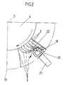
- a section of a bristle 3 in its various positions illustrates which movements a bristle 3 executes when it passes through the distributor pipe.
- the bristle 3 illustrated in full lines in FIG. 2 shows it in the position in which it steps against the circumference of the distributor pipe 18.
- the entire washing device 1 After cleaning the blanket cylinder 2 or its outer surface 8, the entire washing device 1 is deactivated.
Landscapes
- Inking, Control Or Cleaning Of Printing Machines (AREA)
Abstract
Description
Die Erfindung betrifft eine Wascheinrichtung zur Reinigung eines Zylinders einer Druckmaschine gemäß Gattungsbegriff des Anspruchs 1.The invention relates to a washing device for cleaning a cylinder of a printing press according to the preamble of claim 1.
Derartige Wascheinrichtungen werden aus Gründen einer guten Druckqualität eingesetzt. Aus der DE-AS 1 124 974 ist eine Wascheinrichtung eines Gummituchzylinders einer Offset-Druckmaschine bekannt, welche zwei dicht beieinander angeordnete, mit dem Gummituchzylinder unmittelbar in Berührung stehende Bürstenwalzen aufweist, wobei die Waschflüssigkeit durch die hohl ausgebildeten Achsen der Walzen zugeführt wird und durch über den Umfang der Achsen angeordnete Bohrungen austritt. An den einander sich gegenüberliegenden Mantelflächen der Bürstenwalzen ist eine Mehrzahl von Drähten vorgesehen, welche das Ablenkelement darstellen. Durch die das Ablenkelement bildenden Drähte sollen die an der jeweiligen Berührungsstelle mit dem Gummituchzylinder abgeschleuderten Schmutz- und Waschflüssigkeitsteilchen der jeweils benachbarten Bürstenwalze zugeschleudert werden. Das bedeutet, daß entsprechende Schmutzteilchen von einer Bürstenwalze zur anderen gelangen und damit noch entfernt werden müssen. Sodann entsteht durch die Zuführung der Waschflüssigkeit durch die Achsen der Bürstenwalze neben einem erheblichen Waschflüssigkeitsbedarf ein erhöhter Bauaufwand, und zwar im Hinblick auf entsprechende Dichtungen etc.Such washing devices are used for reasons of good print quality. From DE-AS 1 124 974 a washing device of a blanket cylinder of an offset printing press is known, which has two closely arranged brush rollers that are in direct contact with the blanket cylinder, the washing liquid being fed through the hollow axes of the rollers and through bores arranged around the circumference of the axes. A plurality of wires, which represent the deflection element, are provided on the mutually opposite lateral surfaces of the brush rollers. Through the wires forming the deflection element, the dirt and washing liquid particles thrown off at the respective contact point with the rubber blanket cylinder are to be thrown towards the respectively adjacent brush roller. This means that corresponding dirt particles get from one brush roller to the other and therefore still have to be removed. Then, the supply of the washing liquid through the axes of the brush roller, in addition to a considerable washing liquid requirement, results in increased construction costs, with regard to appropriate seals, etc.
Die Erfindung hat sich daher die Aufgabe gestellt, eine Wascheinrichtung der in Rede stehenden Art von einfachem Aufbau so auszugestalten, daß sich ein gesteigerter Wascheffekt bei geringem Waschflüssigkeitsverbrauch ergibt.The object of the invention is therefore to design a washing device of the type in question of simple construction in such a way that there is an increased washing effect with low washing liquid consumption.
Diese Aufgabe ist bei der im Anspruch 1 angegebenen Erfindung gelöst.This object is achieved in the invention specified in claim 1.
Die Unteransprüche stellen vorteilhafte Weiterbildungen des Gegenstands des Anspruchs 1 dar.The subclaims represent advantageous developments of the subject matter of claim 1.
Zufolge derartiger Ausgestaltung ist eine gattungsgemäße Wascheinrichtung geschaffen, die sich insbesondere durch einen erhöhten Gebrauchswert auszeichnet. Das Ablenkelement ist als im Drehbereich der Borsten der Bürstenwalze liegendes Verteilerrohr ausgebildet, so daß dieses eine Doppelfunktion erfüllt: Einerseits dient es zur Ablenkung der Borsten, wobei durch ein Entlangwandern der Borsten an dem Ablenkelement und eine nachfolgende federnde Rückstellbewegung der Borsten ein mechanischer Reinigungseffekt erzielt wird. Andererseits dient das Verteilerrohr auch zur Zuführung der Waschflüssigkeit durch die in diesem radial zur Bürstenachse ausgerichteten Austrittsöffnungen. Da das Verteilerrohr nicht, wie beim Stand der Technik, mit der Bürstenwalze umläuft, können die baulichen Maßnahmen zur Abdichtung gering gehalten werden. Vorteilhafterweise erfolgt der Austritt der Waschflüssigkeit unmittelbar am Ort der mechanischen Reinigung der Borsten selbst. Nachdem die Waschflüssigkeit die Austrittsöffnungen verlassen hat, strömt sie vorerst in Richtung der Bürstenachse und benetzt dabei die Borsten, an welchen die vom Gummituchzylinder abgetragenen Farb- und Papierreste anhaften. Die rotierende Bürstenwalze führt sodann zu einer Umkehrung der Strömungsrichtung der auf die Borsten gelangten Waschflüssigkeit durch Fliehkraft. Gleichzeitig müssen die Borsten das in ihrem Drehbereich befindliche Verteilerrohr unter Ablenkung passieren. Dies führt dazu, daß die Borsten sich zufolge ihrer inneren Elastizität verbiegen und überlagernd eine Abstreifbewegung entlang des Verteilerrohres ausführen dahingehend, daß hierbei etwaige, an den Borsten befindliche Verunreinigungen in Richtung des Endes der Borsten befördert werden. Sobald die Borstenspitzen das Verteilerrohr passiert haben, tritt durch die sich zurückstellenden Borsten eine Beschleunigung auf, die dazu führt, daß noch an den Borsten befindliche Verunreinigungen abgeschleudert werden verbunden mit einer wirksamen Reinigung der Borsten der Bürstenwalze. Dieser Hin- und Zurückfluß der Waschflüssigkeit an den Borsten der Bürstenwalze führt zu einem Ausschwemmeffekt verbunden mit guten Reinigungsergebnissen bei geringem Waschflüssigkeitsbedarf. Die gute Reinigung der Bürstenwalze ermöglicht eine gründlichere Reinigung des Gummituchzylinders. Ferner ist eine Produktionssteigerung durch kürzere Maschinenstillstandszeiten - bedingt durch kürzere Waschzeiten - möglich. Da sich während des Ausschwemmens der Verunreinigungen die befeuchteten Borsten ständig am Verteilerrohr vorbeibewegen und einen Umspüleffekt erzeugen, ist dieses weitgehend von Ansammlungen von Verunreinigungen befreit. Im übrigen ist das Verteilerrohr so angeordnet, daß die abgeschleuderten Teilchen von Verunreinigungen nicht in Richtung des Gummituchzylinders gelenkt werden, sondern bestimmungsgemäß in eine die Wascheinrichtung unterfangende Auffangwanne. Insbesondere erweist sich die Anordnung des Verteilerrohres etwa 45° vor dem tiefsten Punkt der Bürstenachse als günstige Lösung. Das Verteilerrohr über einen oberhalb desselben angeordneten Vorratsbehälters zu speisen, führt zu einer insgesamt technisch einfachen Ausgestaltung. Entsprechende, gesondert anzutreibende Förderpumpen können demgemäß entfallen. Es ist eine solche Anordnung des Behälters und Dimensionierung der Austrittsöffnungen getroffen, daß sich an diesen ein Waschflüssigkeitsstrahl ausbildet, welcher in Richtung der Achse der Bürstenwalze gelenkt wird. Die Reinigungswirkung erstreckt sich demgemäß über einen größeren Bereich der Borsten. Die Anordnung der Bürstenwalze bezogen auf den Gummituchzylinder ist dabei derart, daß die Bürstenwalzen-Achse unterhalb der Achse des Gummituchzylinders verläuft. Vorstehende Maßnahme schafft eine günstige Voraussetzung, der Bürstenwalze - in Drehrichtung des Gummituchzylinders gesehen - eine an dem Gummituchzylinder abrollende Gummiwalze vorzuordnen, um den Waschvorgang der Gummituchwalze zu beschleunigen. Als Beschleuniger tritt sodann noch eine an der Gummiwalze abrollende Rakelwalze auf. Letztere wirkt zur mechanischen Abstreifung von Verunreinigungen mit einem Rakel zusammen, indem die von der Gummiwalze zur Rakelwalze gelangenden Farb- und Papierteilchen weitgehend entfernt werden. Verstärkt wird die Reinigungswirkung durch die Maßnahme, die oberhalb der Bürstenwalze angeordnete Gummiwalze mit dem Gummituchzylinder, der Bürstenwalze und der Rakelwalze in Kontakt zu bringen. Eine geschlossene Walzenanordnung mit optimaler Reinigungswirkung wird dadurch erreicht, daß auch die Rakelwalze mit der Bürstenwalze in Berührung steht. Es findet daher eine gegenseitige Beeinflussung statt, die darauf gezielt ist, vorhandene Verunreinigungen beschleunigt zu entfernen und in die Auffangwanne zu leiten.As a result of such a configuration, a generic washing device is created, which is characterized in particular by an increased utility value. The deflecting element is designed as a distributor tube lying in the range of rotation of the bristles of the brush roller, so that it fulfills a double function: on the one hand, it serves to deflect the bristles, whereby a mechanical cleaning effect is achieved by moving the bristles along the deflecting element and a subsequent resilient return movement of the bristles . On the other hand, the distributor pipe also serves to supply the washing liquid through the outlet openings, which are oriented radially to the brush axis. Since the distributor pipe does not rotate with the brush roller, as in the prior art, the structural measures for sealing can be kept low. Advantageously, the washing liquid emerges directly at the location of the mechanical cleaning of the bristles themselves. After the washing liquid has left the outlet openings, it initially flows in the direction of the brush axis and thereby wets the bristles to which the ink and paper residues removed from the blanket cylinder adhere. The rotating brush roller then reverses the direction of flow of the washing liquid which has reached the bristles by centrifugal force. At the same time, the bristles must pass through the distributor pipe in their rotating area with deflection. This leads to the fact that the bristles bend due to their internal elasticity and carry out a superimposing wiping movement along the distributor pipe in such a way that any contaminants present on the bristles in Towards the end of the bristles. As soon as the bristle tips have passed through the distributor tube, the bristles that are set back accelerate, which leads to impurities that are still on the bristles being thrown off, combined with an effective cleaning of the bristles of the brush roller. This back and forth flow of the washing liquid at the bristles of the brush roller leads to a washout effect combined with good cleaning results with a low washing liquid requirement. Good cleaning of the brush roller enables the blanket cylinder to be cleaned more thoroughly. It is also possible to increase production through shorter machine downtimes - due to shorter washing times. Since the moistened bristles constantly move past the distributor pipe and produce a rinsing effect while the contaminants are being flushed out, this is largely freed of accumulations of contaminants. Otherwise, the distributor pipe is arranged in such a way that the spun off particles of impurities are not directed in the direction of the blanket cylinder, but rather as intended into a collecting trough underneath the washing device. In particular, the arrangement of the distributor pipe about 45 ° before the lowest point of the brush axis has proven to be a favorable solution. Feeding the distributor pipe via a storage container arranged above the same leads to an overall technically simple configuration. Corresponding, separately driven feed pumps can accordingly be dispensed with. It is such an arrangement of the container and dimensioning of the outlet openings that a wash liquid jet is formed there, which is directed in the direction of the axis of the brush roller. The cleaning effect accordingly extends over a larger area of the bristles. The arrangement of the brush roller relative to the blanket cylinder is such that the brush roller axis runs below the axis of the blanket cylinder. Above Measure creates a favorable prerequisite for arranging the brush roller - seen in the direction of rotation of the blanket cylinder - a rubber roller rolling off the blanket cylinder in order to accelerate the washing process of the blanket roller. A squeegee roller rolling on the rubber roller then occurs as an accelerator. The latter interacts with a doctor blade for mechanical wiping of contaminants by largely removing the ink and paper particles that come from the rubber roller to the doctor roller. The cleaning effect is enhanced by the measure of bringing the rubber roller arranged above the brush roller into contact with the blanket cylinder, the brush roller and the doctor roller. A closed roller arrangement with optimal cleaning effect is achieved in that the doctor roller is in contact with the brush roller. There is therefore a mutual influence that is aimed at accelerating the removal of existing contaminants and passing them into the sump.
Nachstehend ist die Erfindung noch weiter anhand der beiliedenden Zeichnung - die jedoch lediglich ein Ausführungsbeispiel darstellt - erläutert. Hierbei zeigt:
- Fig. 1
- in schematischer Darstellung eine Stirnansicht der Wascheinrichtung in Betriebsstellung; und
- Fig. 2
- in vergrößerter Darstellung einen Ausschnitt der Bürstenwalze im Bereich des Verteilerrohres unter Veranschaulichung einer sich an dem Verteilerrohr vorbeibewegenden. Borste in nachfolgenden Drehwinkelstellungen der Bürstenwalze.
- Fig. 1
- a schematic representation of an end view of the washing device in the operating position; and
- Fig. 2
- an enlarged view of a section of the brush roller in the area of the distributor pipe, illustrating a moving past the distributor pipe. Bristle in subsequent rotation angle positions of the brush roller.
Die als Ganzes mit der Ziffer 1 bezeichnete Wascheinrichtung ist einem ausschnittsweise veranschaulichten, in Pfeilrichtung x antreibbaren Gummituchzylinder 2 zugeordnet. Ein wesentlicher Bestandteil der Wascheinrichtung 1 ist eine drehbar angetriebene, Borsten 3 aufweisende Bürstenwalze 4. Deren Achse 5 erstreckt sich unterhalb der Achse 6 des Gummituchzylinders 2. Die durch beide Achsen 5, 6 gehende Verbindungslinie 7 schließt dabei zur Horizontalen einen Winkel β von etwa 20° ein.The washing device designated as a whole by the number 1 is assigned to a
In Drehrichtung des Gummituchzylinders x vorgelagert zu der Bürstenwalze 4 ist eine an dem Gummituchzylinder 2 bzw. dessen Mantelfläche 8 abrollende Gummiwalze 9. Mit strichpunktierten Linien ist in Fig. 1 veranschaulicht, daß letztere in vertikaler Richtung verstellbar ist. Die in Fig. 1 mit einer vollen Linie veranschaulichte Gummiwalze 9 kontaktiert neben dem Gummituchzylinder 2 die Bürstenwalze 4. Ferner rollt an der Gummiwalze 9 eine Rakelwalze 10 ab. Letztere steht wiederum mit der Bürstenwalze 4 in Berührung. Die Durchmesser der Rakelwalze 10 und der Gummiwalze 9 sind kleiner als der von den Borstenspitzen gebildete Durchmesser der Bürstenwalze 4. Ferner ist aus Fig. 1 ersichtlich, daß die Gummiwalzenachse 11 oberhalb der Achse 6 des Gummituchzylinders 2 angeordnet ist.In the direction of rotation of the rubber blanket cylinder x upstream of the brush roller 4 is a
Die Rakelwalze 10 wirkt zusammen mit einem Rakel 12 zur mechanischen Abstreifung von Verunreinigungen. Letztere gelangen über die Gummiwalze 9 und die Bürstenwalze 4 auf die Mantelfläche der Rakelwalze 10 und werden dann von dem Rakel 12 abgestreift. Letzteres erstreckt sich über die gesamte Länge der Rakelwalze 10, deren Länge der der übrigen Walzen entspricht. Das Rakel 12 ist von einem Federelement 13 getragen, welches an einer Einstellvorrichtung 14 sitzt.The
Die gesamte Wascheinrichtung 1 ist unterfangen von einer Auffangwanne 15 für Waschflüssigkeit. Letztere gelangt aus einem unter Atmosphärendruck stehenden Vorratsbehältnis 16 über ein Zulaufrohr 17 zu einem als Verteilerrohr 18 ausgebildeten Ablenkelement. Das Verteilerrohr 18 ist in Drehrichtung vor dem tiefsten Punkt 19 des durch die Borsten bestrichenen Drehbereiches angeordnet, und zwar in einem Winkel alpha von etwa 45° vor dem tiefsten Punkt 19. Ferner ist das Verteilerrohr 18 mit radial zur Bürstenachse 5 gerichteten Austrittsöffnungen 20 versehen. Der Lochabstand der Austrittsöffnungen beträgt etwa 10mm, so daß eine gleichmäßige Benetzung der Bürstenwalze durch die Austrittsöffnungen 20 erfolgt. Seine Festlegung findet das Verteilerrohr 18 mittels eines Halters 21, so daß während einer Reinigung das Verteilerrohr 18 in seiner bestimmungsgemäßen Lage verbleibt.The entire washing device 1 is undertaken by a
Durch eine entsprechende Höhenlage des Vorratsbehältnisses 16 oberhalb des Verteilerrohres 18 und abgestimmte Dimensionierung der Austrittsöffnungen 20 bildet sich ein in Richtung der Achse 5 der Bürstenwalze 4 gerichteter Waschflüssigkeitsstrahl 22.A corresponding liquid level of the
Während der Reinigung des Gummituchzylinders 2 findet durch die Gummiwalze 9 ein Anlösen der auf der Mantelfläche 8 des Gummituchzylinders 2 befindlichen Verunreinigungen wie Farb- und Papierreste statt. Gegenbenenfalls kann die Gummiwalze 9 unabhängig von der Bürstenwalze 4 benetzt werden. Die an der Mantelfläche der Gummiwalze 9 anhaftenden Verunreinigungen gelangen zum Teil auf die Rakelwalze 10 und werden von dort durch das Rakel 12 entfernt. Ebenfalls nehmen die Borsten 3 entsprechende Verunreinigungen von der Mantelfläche der Gummiwalze 9 ab und tragen sie zum Teil zur Rakelwalze 10. Die entgegengesetzt zur Drehrichtung x des Gummituchzylinders 2 angetriebene Bürstenwalze 4 führt dabei eine Traversierbewegung von 4 bis 5mm aus. Die an den Borsten 3 befindlichen Verunreinigungen werden wirkungsvoll von dem ein Sprührakel bildenden Verteilerrohr 18 entfernt, so daß dadurch auch der Gummituchzylinder 2 einer beschleunigten Reinigung unterliegt. Der aus den Austrittsöffnungen 20 des Verteilerrohres 18 kommende Flüssigkeitsstrahl 22 gelangt bis zur Wurzel der Borsten 3 und erfährt zufolge Fliehkraft von da aus eine nach auswärts gerichtete Umlenkung, wobei etwaige an den Borsten 3 anhaftende Verunreinigungen mitgenommen werden. In Fig. 2 ist ausschnittsweise anhand einer Borste 3 in deren verschiedenen Stellungen veranschaulicht, welche Bewegungen eine Borste 3 beim Passieren des Verteilerrohres ausführt. Die in Fig. 2 mit vollen Linien veranschaulichte Borste 3 zeigt sie in der Stellung, in welcher sie gegen den Umfang des Verteilerrohres 18 tritt. Aus den folgenden Drehwinkelstellungen, veranschaulicht durch strichpunktierte Darstellung der Borste 3, geht hervor, daß sie entgegen ihrer inneren Elastizität eine Biegung erfährt. Zufolge der Drehbewegung der Bürstenwalze 4 findet dabei ein Vorbeistreifen des Borstenendes an dem Verteilerrohr 18 statt, wobei Verunreinigungen ebenfalls zu dem Borstenende geleitet werden. Dieses ist dabei unterstützt durch die entlang der Borste 3 verlaufende Waschflüssigkeit. Sobald die Bürstenwalze sich genügend weit gedreht hat, findet die Borstenspitze nicht mehr genügend Abstützung an dem Verteilerrohr 18, so daß die Rückstellung der Borste erfolgen kann verbunden mit einem Schleudereffekt auf die Verunreinigungen in Richtung des Bodens der Auffangwanne 15. Ein Anhaften von Verunreinigungen am Verteilerrohr 18 ist auch weitgehend vermieden, da die Borsten ständig an diesem vorbeischleifen. Da ferner das Verteilerrohr 18 ständig durch die in Auswärtsrichtung wandernde Waschflüssigkeit umspült wird, ergibt sich, insgesamt gesehen, ein von innen nach außen gerichteter Schwemmeffekt.During the cleaning of the
Nach durchgeführter Reinigung des Gummituchzylinders 2 bzw. dessen Mantelfläche 8 wird die gesamte Wascheinrichtung 1 außer Wirkung gebracht.After cleaning the
Claims (11)
- Washing device for cleaning a cylinder of a printing machine, for example a blanket cylinder of an offset printing machine, having a rotatably driven brush roller which has bristles for interaction with the blanket cylinder, washing liquid being fed to the bristles for the self-cleaning thereof, and a deflection element, which is stationary relative to the brush roller and extends over the length thereof, being arranged in one area of rotation of the bristles, past which deflection element the bristles rub with subsequent restoration, characterised in that the deflection element is constructed as a distribution pipe (18) having outlet openings (20), directed radially towards the brush axis (5), for the washing liquid.
- Washing device, in particular according to Claim 1, characterised in that the distribution pipe (18) is arranged ahead of the lowest point (19) of the area of rotation along which the bristles (3) rub, in the direction of rotation.
- Washing device according to Claim 2, characterised in that the distribution pipe (18) is arranged approximately 45° ahead of the lowest point (19).
- Washing device, in particular according to one or more of the preceding claims, characterised in that the distribution pipe (18) is fed by means of a feed pipe (17) from a supply container (16) which is located above the distribution pipe (18) and is at atmospheric pressure.
- Washing device, in particular according to one or more of the preceding claims, characterised in that a jet (22) of washing liquid is formed at the outlet openings (20).
- Washing device, in particular according to one or more of the preceding claims, characterised in that the axis (5) of the brush roller (4) is arranged below the axis (6) of the blanket cylinder (2).
- Washing device, in particular according to one or more of the preceding claims, characterised in that a rubber-covered roller (9), which rolls off on the blanket cylinder (2), is arranged in the direction of rotation (x) of the blanket cylinder (2), ahead of the brush roller (4).
- Washing device according to Claim 7, characterised in that a doctor roller (10) rolls off on the rubber-covered roller (9).
- Washing device according to Claim 8, characterised in that the doctor roller (10) interacts with a doctor (12) for mechanically scraping off impurities.
- Washing device, in particular according to one or more of the preceding claims, characterised in that the rubber-covered roller (9), arranged above the brush roller (4), is in contact with the blanket cylinder (2), the brush roller (4) and the doctor roller (10).
- Washing device, in particular according to one or more of the preceding claims, characterised in that the doctor roller (10) is in contact with the brush roller (4).
Priority Applications (1)
| Application Number | Priority Date | Filing Date | Title |
|---|---|---|---|
| AT90103653T ATE92844T1 (en) | 1989-03-24 | 1990-02-26 | WASHING DEVICE FOR CLEANING A CYLINDER OF A PRINTING PRESS. |
Applications Claiming Priority (2)
| Application Number | Priority Date | Filing Date | Title |
|---|---|---|---|
| DE3909819A DE3909819A1 (en) | 1989-03-24 | 1989-03-24 | WASHING DEVICE FOR CLEANING A CYLINDER OF A PRINTING MACHINE |
| DE3909819 | 1989-03-24 |
Publications (3)
| Publication Number | Publication Date |
|---|---|
| EP0388664A2 EP0388664A2 (en) | 1990-09-26 |
| EP0388664A3 EP0388664A3 (en) | 1991-05-02 |
| EP0388664B1 true EP0388664B1 (en) | 1993-08-11 |
Family
ID=6377176
Family Applications (1)
| Application Number | Title | Priority Date | Filing Date |
|---|---|---|---|
| EP90103653A Expired - Lifetime EP0388664B1 (en) | 1989-03-24 | 1990-02-26 | Cleaning device for a cylinder in a printing machine |
Country Status (5)
| Country | Link |
|---|---|
| US (1) | US5035178A (en) |
| EP (1) | EP0388664B1 (en) |
| JP (1) | JPH0722993B2 (en) |
| AT (1) | ATE92844T1 (en) |
| DE (2) | DE3909819A1 (en) |
Cited By (1)
| Publication number | Priority date | Publication date | Assignee | Title |
|---|---|---|---|---|
| EP1859938A2 (en) | 2006-05-22 | 2007-11-28 | Heidelberger Druckmaschinen Aktiengesellschaft | Device for cleaning a cylinder in a printing press |
Families Citing this family (17)
| Publication number | Priority date | Publication date | Assignee | Title |
|---|---|---|---|---|
| JPH05162295A (en) * | 1991-11-20 | 1993-06-29 | Baldwin Printing Controls Ltd | Cylinder washing apparatus for printing machine |
| US5257578A (en) * | 1993-01-12 | 1993-11-02 | Heidelberger Druckmaschinen Ag | Device for automatically cleaning blanket cylinders in a offset printing press |
| JP2546621B2 (en) * | 1993-02-12 | 1996-10-23 | ロックウェル インターナショナル コーポレイション | Printer with remaining ink recycling device |
| DE9403228U1 (en) * | 1994-02-26 | 1994-04-21 | Heidelberger Druckmaschinen Ag, 69115 Heidelberg | Washing device for washing the outer surface of a cylinder of a printing press |
| DE4416127C2 (en) * | 1994-05-06 | 2000-11-30 | Heidelberger Druckmasch Ag | Cleaning device for cylinders of a printing press |
| DE4426079A1 (en) * | 1994-07-22 | 1996-01-25 | Baldwin Gegenheimer Gmbh | Device for cleaning rollers |
| US5575211A (en) * | 1994-10-28 | 1996-11-19 | Hycorr Machine Corporation | Washing Arrangement for rotary printer |
| DE19702082B4 (en) * | 1997-01-22 | 2005-10-13 | Heidelberger Druckmaschinen Ag | Washing device in the printing unit of rotary printing machines |
| US5893012A (en) * | 1998-02-17 | 1999-04-06 | Imation Corp. | Apparatus and method for removal of back-plated developer |
| US20020157205A1 (en) * | 2001-04-27 | 2002-10-31 | Akira Hara | Cylinder cleaning brush unit |
| US20040173240A1 (en) * | 2002-09-13 | 2004-09-09 | Paul Harris | Brush for a blanket wash system |
| JP2005001243A (en) * | 2003-06-12 | 2005-01-06 | Baldwin Japan Ltd | Cleaning liquid feeder for cylinder cleaning, brush unit for cleaning cylinder and cylinder cleaning device |
| DE102006036710A1 (en) * | 2006-08-05 | 2008-02-07 | Sms Demag Ag | Device for applying a brush to a roller |
| JP4957958B2 (en) * | 2006-12-21 | 2012-06-20 | 独立行政法人 国立印刷局 | Blanket cylinder dust remover |
| CN103991273A (en) * | 2014-05-28 | 2014-08-20 | 太仓市鑫鹤印刷包装有限公司 | Novel paper tube printing machine structure |
| CN106733731B (en) * | 2017-03-09 | 2023-09-08 | 合肥美亚光电技术股份有限公司 | Background device of color sorter |
| CN110143052B (en) * | 2019-06-14 | 2020-02-14 | 温州市泰昌胶粘制品有限公司 | Printing method of adhesive sticker product |
Family Cites Families (11)
| Publication number | Priority date | Publication date | Assignee | Title |
|---|---|---|---|---|
| DE314053C (en) * | 1900-01-01 | |||
| DE315570C (en) * | 1900-01-01 | |||
| US1082409A (en) * | 1911-05-23 | 1913-12-23 | Cottrell C B & Sons Co | Offset mechanism for printing-machines. |
| US2705455A (en) * | 1950-05-31 | 1955-04-05 | Schnellpressenfab Heidelberg | Means for cleaning the inking roller system of platen type printing presses |
| US2952859A (en) * | 1958-03-19 | 1960-09-20 | John H Alcamo | Surgeons' pre-operating scrubbing machine |
| DE1124974B (en) * | 1960-11-19 | 1962-03-08 | Roland Offsetmaschf | Cleaning device for the blanket cylinder of offset printing machines |
| FR2010455A1 (en) * | 1969-01-27 | 1970-02-20 | Arnaud Jacques | |
| US4015307A (en) * | 1969-08-25 | 1977-04-05 | Oxy-Dry Sprayer Corporation | Apparatus for cleaning rotating cylindrical surfaces |
| US3809105A (en) * | 1972-01-05 | 1974-05-07 | Hoechst Co American | Apparatus for processing two sides of a printing plate |
| DE3614496A1 (en) * | 1986-04-29 | 1987-11-05 | Heidelberger Druckmasch Ag | WASHING DEVICE FOR PRINTING CYLINDERS OF PRINTING MACHINES |
| DE3806609C2 (en) * | 1987-03-28 | 1996-10-17 | Heidelberger Druckmasch Ag | Washing device for washing the outer surface of a blanket cylinder of an offset printing machine |
-
1989
- 1989-03-24 DE DE3909819A patent/DE3909819A1/en active Granted
-
1990
- 1990-02-26 DE DE9090103653T patent/DE59002241D1/en not_active Expired - Fee Related
- 1990-02-26 EP EP90103653A patent/EP0388664B1/en not_active Expired - Lifetime
- 1990-02-26 AT AT90103653T patent/ATE92844T1/en not_active IP Right Cessation
- 1990-03-23 JP JP2072252A patent/JPH0722993B2/en not_active Expired - Fee Related
- 1990-03-26 US US07/499,028 patent/US5035178A/en not_active Expired - Lifetime
Cited By (2)
| Publication number | Priority date | Publication date | Assignee | Title |
|---|---|---|---|---|
| EP1859938A2 (en) | 2006-05-22 | 2007-11-28 | Heidelberger Druckmaschinen Aktiengesellschaft | Device for cleaning a cylinder in a printing press |
| DE102006023896A1 (en) * | 2006-05-22 | 2007-11-29 | Heidelberger Druckmaschinen Ag | Device for cleaning a cylinder of a printing machine |
Also Published As
| Publication number | Publication date |
|---|---|
| EP0388664A2 (en) | 1990-09-26 |
| EP0388664A3 (en) | 1991-05-02 |
| US5035178A (en) | 1991-07-30 |
| JPH02279340A (en) | 1990-11-15 |
| DE3909819A1 (en) | 1990-09-27 |
| ATE92844T1 (en) | 1993-08-15 |
| DE59002241D1 (en) | 1993-09-16 |
| DE3909819C2 (en) | 1992-07-30 |
| JPH0722993B2 (en) | 1995-03-15 |
Similar Documents
| Publication | Publication Date | Title |
|---|---|---|
| EP0388664B1 (en) | Cleaning device for a cylinder in a printing machine | |
| EP0818574B1 (en) | Cleaning device | |
| DE2815388A1 (en) | DEVICE FOR WASHING CYLINDERS ON PRINTING MACHINES, IN PARTICULAR OFFSET PRINTING MACHINES | |
| DE69718007T2 (en) | DEVICE AND METHOD FOR CLEANING FLEXOGRAPHIC PRINTING PLATES | |
| DE2739556C2 (en) | Device for the continuous cleaning of a wiping cylinder in a steel intaglio printing machine | |
| CH677754A5 (en) | ||
| DE3308980A1 (en) | WASHING DEVICE FOR A RUBBER BLANKET CYLINDER OF A PRINTING MACHINE | |
| DE4238201A1 (en) | ||
| DE3806609A1 (en) | WASHING DEVICE FOR WASHING THE SHEATH SURFACE OF A RUBBER PAD CYLINDER OF AN OFFSET PRINTING MACHINE | |
| DE4443356C2 (en) | Process for cleaning a cylinder of a rotary printing press | |
| DE2751618C2 (en) | Washing device with rotating driven washing device | |
| DE2520919B2 (en) | WASHING EQUIPMENT FOR CLEANING THE RUBBER CYLINDER OF AN OFFSET PRINTING MACHINE | |
| EP0692381A2 (en) | Apparatus for removing ink of an inking device | |
| EP0381830A2 (en) | Device for cleaning the blanket cylinder of an offset printing machine | |
| EP2818424A1 (en) | System and method for cleaning rotatable elements of a labelling unit | |
| DE69007582T2 (en) | Method and arrangement for cleaning guide rollers. | |
| DE102018104534B3 (en) | SPRAY TUBE AND PRESSURE MACHINE ROLLER CLEANING DEVICE WITH A SPRAY TUBE | |
| DE102008004073B4 (en) | Device for cleaning cylinders of a printing machine | |
| DE10027023B4 (en) | Devices for cleaning a roller or a cylinder | |
| DD259600A1 (en) | DEVICE FOR WASHING A CYLINDER OF A PRINTING MACHINE | |
| DE4203914A1 (en) | Cleaner for printing cylinder of printing machine - has oscillating cleaning head mounted on rail parallel to cylinder | |
| DE19860859A1 (en) | Device for cleaning a roller | |
| DE10027021B4 (en) | Device for cleaning a roller or a cylinder | |
| DE10320951B4 (en) | Cleaning device for a printing press cylinder | |
| DE4437018B4 (en) | press |
Legal Events
| Date | Code | Title | Description |
|---|---|---|---|
| PUAI | Public reference made under article 153(3) epc to a published international application that has entered the european phase |
Free format text: ORIGINAL CODE: 0009012 |
|
| 17P | Request for examination filed |
Effective date: 19900226 |
|
| AK | Designated contracting states |
Kind code of ref document: A2 Designated state(s): AT CH DE FR GB LI |
|
| PUAL | Search report despatched |
Free format text: ORIGINAL CODE: 0009013 |
|
| AK | Designated contracting states |
Kind code of ref document: A3 Designated state(s): AT CH DE FR GB LI |
|
| 17Q | First examination report despatched |
Effective date: 19930128 |
|
| GRAA | (expected) grant |
Free format text: ORIGINAL CODE: 0009210 |
|
| AK | Designated contracting states |
Kind code of ref document: B1 Designated state(s): AT CH DE FR GB LI |
|
| REF | Corresponds to: |
Ref document number: 92844 Country of ref document: AT Date of ref document: 19930815 Kind code of ref document: T |
|
| REF | Corresponds to: |
Ref document number: 59002241 Country of ref document: DE Date of ref document: 19930916 |
|
| ET | Fr: translation filed | ||
| GBT | Gb: translation of ep patent filed (gb section 77(6)(a)/1977) |
Effective date: 19931103 |
|
| PLBE | No opposition filed within time limit |
Free format text: ORIGINAL CODE: 0009261 |
|
| STAA | Information on the status of an ep patent application or granted ep patent |
Free format text: STATUS: NO OPPOSITION FILED WITHIN TIME LIMIT |
|
| 26N | No opposition filed | ||
| PGFP | Annual fee paid to national office [announced via postgrant information from national office to epo] |
Ref country code: AT Payment date: 19970123 Year of fee payment: 8 |
|
| PG25 | Lapsed in a contracting state [announced via postgrant information from national office to epo] |
Ref country code: AT Free format text: LAPSE BECAUSE OF NON-PAYMENT OF DUE FEES Effective date: 19980226 |
|
| PGFP | Annual fee paid to national office [announced via postgrant information from national office to epo] |
Ref country code: GB Payment date: 20010125 Year of fee payment: 12 |
|
| PGFP | Annual fee paid to national office [announced via postgrant information from national office to epo] |
Ref country code: FR Payment date: 20010222 Year of fee payment: 12 |
|
| PGFP | Annual fee paid to national office [announced via postgrant information from national office to epo] |
Ref country code: CH Payment date: 20010302 Year of fee payment: 12 |
|
| REG | Reference to a national code |
Ref country code: GB Ref legal event code: IF02 |
|
| PG25 | Lapsed in a contracting state [announced via postgrant information from national office to epo] |
Ref country code: GB Free format text: LAPSE BECAUSE OF NON-PAYMENT OF DUE FEES Effective date: 20020226 |
|
| PG25 | Lapsed in a contracting state [announced via postgrant information from national office to epo] |
Ref country code: LI Free format text: LAPSE BECAUSE OF NON-PAYMENT OF DUE FEES Effective date: 20020228 Ref country code: CH Free format text: LAPSE BECAUSE OF NON-PAYMENT OF DUE FEES Effective date: 20020228 |
|
| REG | Reference to a national code |
Ref country code: CH Ref legal event code: PL |
|
| GBPC | Gb: european patent ceased through non-payment of renewal fee |
Effective date: 20020226 |
|
| PG25 | Lapsed in a contracting state [announced via postgrant information from national office to epo] |
Ref country code: FR Free format text: LAPSE BECAUSE OF NON-PAYMENT OF DUE FEES Effective date: 20021031 |
|
| REG | Reference to a national code |
Ref country code: FR Ref legal event code: ST |
|
| PGFP | Annual fee paid to national office [announced via postgrant information from national office to epo] |
Ref country code: DE Payment date: 20070425 Year of fee payment: 18 |
|
| PG25 | Lapsed in a contracting state [announced via postgrant information from national office to epo] |
Ref country code: DE Free format text: LAPSE BECAUSE OF NON-PAYMENT OF DUE FEES Effective date: 20080902 |