EP0387761B1 - Automatic circuit breaker, particularly automatic cut-out - Google Patents
Automatic circuit breaker, particularly automatic cut-out Download PDFInfo
- Publication number
- EP0387761B1 EP0387761B1 EP90104653A EP90104653A EP0387761B1 EP 0387761 B1 EP0387761 B1 EP 0387761B1 EP 90104653 A EP90104653 A EP 90104653A EP 90104653 A EP90104653 A EP 90104653A EP 0387761 B1 EP0387761 B1 EP 0387761B1
- Authority
- EP
- European Patent Office
- Prior art keywords
- arc
- pillars
- webs
- switch according
- contact
- Prior art date
- Legal status (The legal status is an assumption and is not a legal conclusion. Google has not performed a legal analysis and makes no representation as to the accuracy of the status listed.)
- Expired - Lifetime
Links
Images
Classifications
-
- H—ELECTRICITY
- H01—ELECTRIC ELEMENTS
- H01H—ELECTRIC SWITCHES; RELAYS; SELECTORS; EMERGENCY PROTECTIVE DEVICES
- H01H9/00—Details of switching devices, not covered by groups H01H1/00 - H01H7/00
- H01H9/30—Means for extinguishing or preventing arc between current-carrying parts
- H01H9/34—Stationary parts for restricting or subdividing the arc, e.g. barrier plate
- H01H9/346—Details concerning the arc formation chamber
-
- H—ELECTRICITY
- H01—ELECTRIC ELEMENTS
- H01H—ELECTRIC SWITCHES; RELAYS; SELECTORS; EMERGENCY PROTECTIVE DEVICES
- H01H9/00—Details of switching devices, not covered by groups H01H1/00 - H01H7/00
- H01H9/30—Means for extinguishing or preventing arc between current-carrying parts
- H01H9/34—Stationary parts for restricting or subdividing the arc, e.g. barrier plate
- H01H9/342—Venting arrangements for arc chutes
Definitions
- the invention relates to a circuit breaker according to the preamble of claim 1, in particular a miniature circuit breaker in a narrow construction cf. e.g. FR 25 75 861 B1.
- switches with specially designed quenching chambers are known in a variety of designs.
- the previously known switches contain an arc chamber with extinguishing plates assigned to the contact point within their insulating material housing in order to effectively extinguish the switching arc which arises in the event of a short-circuit shutdown.
- a circuit breaker with integrated arcing means in the prechamber area consist of oppositely formed rows of ribs on the housing inner walls of the arc chamber.
- a central channel remains between the rows of ribs, which have a tree-like structure or can also be formed as individual straight walls.
- they are surrounded by grooves or notches, which in turn contain a deionized cold gas reserve and are intended to ensure gas recirculation in the direction of the contact zone when switched off.
- the rib rows which are located freestanding in the middle of the prechamber area, only widen the creepage distance between the contacts, without the arc and the arc gases being guided in a targeted manner.
- the shape and position of the grooves are essentially matched to the fact that a uniform thickness of the ribs is maintained in order to exclude cavities and unevenness in the housing parts. Design and press engineering measures are therefore in the foreground when designing the rib rows of this switch. Optimized gas recirculation and a rapid discharge of the switching arc from the contact point into the quenching plates, however, are not guaranteed with such a quenching chamber.
- the invention has for its object to simplify the quenching chamber within its prechamber area in a self-switch of the aforementioned type, and to provide improved arc guidance and to bring about a particularly low flow resistance in the prechamber space, so that a quick and safe flow of the switching arc from the contact point into the Extinguishing sheet stack is ensured.
- the design of the quenching chamber according to the invention is advantageous in that the switching arc, driven by the magnetic field of the arc guiding rails, is narrowly delimited between the protruding upper sides of webs which are closely adjacent there and from the end faces of a plurality of columns or pegs arranged in a distributed manner in the prechamber space and runs in a narrow gap.
- this results in high arc acceleration with low gas pressure.
- the drive effect of the gas-emitting material of the webs and columns is used in a targeted manner in order to exert an additional drive on the arc. With closed side panels, however, this effect is usually too strong.
- the gas pressure arising in front of the migrating arc can relax in the spaces between the columns, so that the switching arc finds only a slight flow resistance in the direction of the quenching plates and can therefore run quickly and safely from the contact point.
- any backward pressure difference in front of and behind the arc is effectively compensated for by backflow of the gases between the columns.
- This pressure equalization also ensures good deionization of the area at risk of ignition at the contact point behind the arc.
- the web-like sealing walls enlarge the creepage distances at the contact point. Since the web edges are only slightly loaded by the arc, there is a high insulation resistance even when the contacts are open.
- the narrow circuit breaker has a housing (1) composed of two housing shells (1a, 1b), which accommodates a switching and release mechanism (2), which is only indicated, in the upper part.
- the housing (1) made of thermosetting or thermoplastic molding compound is predominantly designed as an extinguishing chamber (3), which is largely filled with an extinguishing sheet stack (4) arranged parallel to the bottom surface (1c) of the switch.
- the depth of the Extinguishing chamber between their at the inner side surfaces (3a, 3b) is predetermined, based on the standardized switch width, by the outer walls of the housing (1a ', 1b') in the wall thickness that is customary in terms of production technology.
- arc guiding rails (6) and (7) which in turn are in the area a contact arrangement (5) located in the prechamber space (3c) of the arcing chamber.
- the contact point with a single break in the funnel-shaped prechamber space (3c) on the right upper edge of the quenching chamber consists of a fixed contact piece (5a) which is connected to an output terminal (11) via current-carrying parts (10a) and a trigger coil (10), and one by one Fixed axis swiveling contact lever (5b). This is connected to an input terminal (13) via movable lines (12a, 12b) with the inclusion of a thermal release (12) and pivots counterclockwise when it is switched off.
- Fixed contact piece (5a) and contact lever (5b) form an approximately U-shaped current loop at the actual contact point of contact together with their current leads. which is oriented perpendicular to the direction of the extinguishing plates (4a).
- the individual quenching plates have an approximately V-shaped incision (4b) on their front side facing the pre-chamber space (3c) and improve the arc run-in and cover the entire open cross-section of the pre-chamber space, which is mainly enclosed by wall parts (1e), with the front contour formed in this way from. Only a recess required for the pivoting movement of the contact lever (5b) is recessed in the wall parts (1e), so that the prechamber space (3c) in connection with the arc guide rails (6, 7) is designed to be almost pressure-tight to the switching and triggering mechanism.
- the upper web (3d) is tight on the fixed contact piece (5a) and follows its contact horn (5a ') on the side facing the prechamber space up to the quenching chamber wall in the area of the upper arc runner (6). Together they include Crosspieces (3d) of both housing shells the fixed contact piece on the contact side and on both narrow sides such that in the middle between the crosspieces (3d) practically only a gap corresponding to the width of the contact lever (5b) remains free along the arcing horn (5a ').
- Another main feature of the invention is a plurality of columns or pins (3f) arranged in the prechamber space (3c) - still referred to only as columns - which are arranged approximately evenly distributed in the free cross section between the webs (3d, 3e).
- the columns (3f) which are round or square in cross-section, have an approximately equal distance from the webs (3d, 3e) and from one another and each extend from the side surfaces (3a, 3b) to almost the pivoting plane of the contact lever (5b), see above that only a narrow gap between their end faces (3f ') continuously remains free.
- the columns (3f) are preferably arranged in a slight zigzag offset to a middle ideal line between the two webs (3d, 3e) from the contact area in the direction of the fire-extinguishing sheet end faces, but can also be arranged directly in a row on this ideal line. Ideally, only two columns are arranged in the funnel-shaped area directly in front of the quenching plates (4a) (FIG. 1, FIG. 3). According to the exemplary embodiment, seven columns (3f) are formed on each housing half-shell (1a, 1b) directly during the manufacture of the housing parts, the columns preferably being slightly frustoconical in shape with an average diameter of approximately 2 mm and a height of approximately 6 mm.
- the arrangement of the columns (3f) is of the named ones Criteria with dependent.
- the number of pillars on each housing part will essentially depend on the size of the prechamber space, while their position should be distributed as evenly as possible between the contact point area and the quenching plate end faces.
- the column groups are in the two housing shells arranged offset to a gap, as indicated in particular in FIG. 2.
- the existing expansion space and the flow channels around the columns also ensure a lower gas pressure, which in turn reduces the ion concentration and reduces the risk of reignitions behind the arc.
- the space behind the fixed contact piece (5a) can serve as a kind of buffer and as a cooling air mass reserve, if the web (3d) that surrounds the contact horn up to the upper arc runner (6) ends approximately with the top of the contact point - this leaves between the end of the contact point Web (3d) and the wall part (1e) a cross-flow channel (8 '), which enables pressure equalization above the contact point to the actual antechamber (3c).
Abstract
Description
Die Erfindung betrifft einen Selbstschalter nach dem Oberbegriff des Patentanspruchs 1, insbesondere einen Leitungsschutzschalter in Schmalbauweise vgl. z.B. FR 25 75 861 B1.The invention relates to a circuit breaker according to the preamble of
Derartige Schalter mit besonders gestalteten Löschkammern sind in einer Vielzahl von Ausführungen bekannt. Beispielsweise sei auf die Gegenstände der DE-PS 1 185 269 sowie DE-PS 1 185 274 verwiesen. Die vorbekannten Schalter enthalten innerhalb ihres Isolierstoffgehäuses eine der Kontaktstelle zugeordnete Lichtbogenkammer mit Löschblechen, um den bei einer Kurzschlußabschaltung entstehenden Schaltlichtbogen wirkungsvoll zu löschen.Such switches with specially designed quenching chambers are known in a variety of designs. For example, reference is made to the subject matter of
Weiterentwicklungen dieser Kammergrundformen sind z. B. in der DE 27 16 619 B1, DE 33 37 562 A1, EP 0 123 090 B1, EP 0 158 124 A2 und EP 0 251 160 A2 beschrieben. All diesen Löscheinrichtungen ist gemeinsam, daß sie mehrere auf Abstand nebeneinander angeordnete Löschbleche und zwei quer davor die Kontaktanordnung flankierende Isolierstoffplatten im sogenannten Vorkammerbereich aufweisen. Die meist aus Keramik oder auch einem Kunststoff bestehenden Isolierstoffplatten sind jeweils mit Abstand zu den Gehäuseaußenwänden angeordnet. Dadurch ist eine Umströmung der Platten durch Lichtbogengase bzw. ein Druckausgleich möglich.Further developments of these basic chamber forms are e.g. B. in DE 27 16 619 B1, DE 33 37 562 A1, EP 0 123 090 B1, EP 0 158 124 A2 and EP 0 251 160 A2. All these quenching devices have in common that they have several quenching plates arranged next to one another at a distance and two insulating material plates flanking the contact arrangement transversely in front of it in the so-called prechamber area. The mostly made of ceramic or a plastic insulating material plates are each spaced from the housing outer walls. Arc gases can flow around the plates or pressure equalization is possible.
Von Nachteil bei diesen Löscheinrichtungen sind die beiden zusätzlichen Isolierstoffplatten, die außer den Teilekosten auch einen entsprechenden Montageaufwand erfordern. Zudem besteht erhebliche Bruchgefahr, wenn Keramikplatten beim Verschließen der Gehäuseteile nicht exakt eingelegt sind oder verrutschen. Funktionsstörungen des Schalters durch im Gehäuse herumfliegende Bruchstücke der Isolierstoffplatten können daher leicht die Folge sein.A disadvantage of these extinguishing devices are the two additional insulating material plates which, in addition to the part costs, also require a corresponding amount of assembly work. There is also a considerable risk of breakage if ceramic plates are not inserted exactly or slide when the housing parts are closed. Malfunctions of the switch due to fragments of the insulating material flying around in the housing can therefore easily result.
Um die Isolierstoffplatten einzusparen, ist es bereits aus der eingangs genannten FR 25 75 861 B1 bekannt, einen Leitungsschutzschalter mit integrierten Lichtbogenführungsmitteln im Vorkammerbereich zu versehen. Diese bestehen aus gegenüberliegend angeformten Rippenreihen an den Gehäuseinnenwänden der Lichtbogenkammer. Zwischen den Rippenreihen, die eine baumartige Struktur aufweisen oder auch als einzelne gerade Wände ausgebildet sein können, verbleibt ein zentraler Kanal. Je nach Formgebung der Rippen sind diese von Nuten oder Kerben umgeben, die ihrerseits eine entionisierte kalte Gasreserve beinhalten und bei einer Abschaltung eine Gasrückführung in Richtung der Kontaktzone gewährleisten sollen. Die etwa mittig im Vorkammerbereich freistehend angeordneten Rippenreihen verbreitern lediglich den Kriechweg zwischen den Kontakten, ohne daß es zu einer gezielten Führung des Schaltlichtbogens und auch der Lichtbogengase kommt. Dabei sind Form und Lage der Nuten im wesentlichen darauf abgestimmt, daß eine gleichmäßige Dicke der Rippen eingehalten wird, um Lunker sowie Unebenheiten der Gehäuseteile auszuschließen. Formgestalterische sowie preßtechnische Maßnahmen stehen also bei der Ausbildung der Rippenreihen dieses Schalters im Vordergrund. Eine optimierte Gasrückführung sowie ein schneller Ablauf des Schaltlichtbogens von der Kontaktstelle in die Löschbleche sind hingegen bei einer derartigen Löschkammer nicht gewährleistet.In order to save the insulating material plates, it is already known from the aforementioned FR 25 75 861 B1 to provide a circuit breaker with integrated arcing means in the prechamber area. These consist of oppositely formed rows of ribs on the housing inner walls of the arc chamber. A central channel remains between the rows of ribs, which have a tree-like structure or can also be formed as individual straight walls. Depending on the shape of the ribs, they are surrounded by grooves or notches, which in turn contain a deionized cold gas reserve and are intended to ensure gas recirculation in the direction of the contact zone when switched off. The rib rows, which are located freestanding in the middle of the prechamber area, only widen the creepage distance between the contacts, without the arc and the arc gases being guided in a targeted manner. The shape and position of the grooves are essentially matched to the fact that a uniform thickness of the ribs is maintained in order to exclude cavities and unevenness in the housing parts. Design and press engineering measures are therefore in the foreground when designing the rib rows of this switch. Optimized gas recirculation and a rapid discharge of the switching arc from the contact point into the quenching plates, however, are not guaranteed with such a quenching chamber.
Der Erfindung liegt die Aufgabe zugrunde, bei einem Selbstschalter der vorgenannten Art die Löschkammer innerhalb ihres Vorkammerbereiches zu vereinfachen, und eine verbesserte Lichtbogenführung zu schaffen sowie einen besonders niedrigen Strömungswiderstand im Vorkammerraum herbeizuführen, so daß ein schneller und sicherer Ablauf des Schaltlichtbogens von der Kontaktstelle in den Löschblechstapel sichergestellt ist.The invention has for its object to simplify the quenching chamber within its prechamber area in a self-switch of the aforementioned type, and to provide improved arc guidance and to bring about a particularly low flow resistance in the prechamber space, so that a quick and safe flow of the switching arc from the contact point into the Extinguishing sheet stack is ensured.
Diese Aufgabe wird durch einen Selbstschalter mit den kennzeichnenden Merkmalen des Patentanspruchs 1 gelöst. Weiterbildungen und vorteilhafte Ausgestaltungen der Erfindung sind Gegenstände der Unteransprüche.This object is achieved by a circuit breaker with the characterizing features of
Die erfindungsgemäße Ausgestaltung der Löschkammer ist insofern vorteilhaft, als der Schaltlichtbogen vom magnetischen Feld der Lichtbogenlaufschienen angetrieben zwischen vorstehenden Oberseiten dort dicht anliegender Stege sowie von Stirnflächen mehrerer im Vorkammerraum verteilt angeordneter Säulen bzw. Zapfen seitlich eng begrenzt wird und in einem schmalen Spalt abläuft. Damit entsteht neben einer besseren Lichtbogenführung eine hohe Lichtbogenbeschleunigung bei geringem Gasdruck. Zugleich wird die Antriebswirkung des gasabgebenden Materials der Stege und Säulen gezielt genutzt, um einen zusätzlichen Antrieb auf den Lichtbogen auszuüben. Bei geschlossenen Seitenplatten ist diese Wirkung hingegen meist schon zu stark. Ferner kann sich der vor dem wandernden Lichtbogen entstehende Gasdruck in den Freiräumen zwischen den Säulen entspannen, so daß der Schaltlichtbogen nur einen geringen Strömungswiderstand in Richtung der Löschbleche vorfindet und somit schnell und sicher von der Kontaktstelle ablaufen kann. Bei der Lichtbogenwanderung wird durch Rückströmung der Gase zwischen den Säulen eine eventuell hemmende Druckdifferenz vor und hinter dem Lichtbogen wirksam ausgeglichen. Dieser Druckausgleich sorgt zugleich für eine gute Entionisierung des neuzündungsgefährdeten Bereiches an der Kontaktstelle hinter dem Lichtbogen. Des weiteren vergrößern die stegartigen Abdichtungswände die Kriechwege an der Kontaktstelle. Da die Stegkanten nur geringfügig durch den Lichtbogen belastet werden, ergibt sich auch bei geöffneten Kontakten eine hohe Isolationsfestigkeit. Ein besonderer Vorteil der Erfindung besteht zusätzlich darin, daß sich die hohe Lichtbogengeschwindigkeit und der geringe Gasdruck im Vorkammerraum nebst den vorbeschriebenen Wirkungen durch unmittelbare Anformung der Säulen und auch der Abdichtungswände bei der Herstellung der Gehäuseteile aus einem Duroplast oder Thermoplast und damit kostenneutral erzielen lassen. Durch Wegfall der beiden bisher meist üblichen Isolierstoffplatten im Vorkammerbereich ergibt sich so insgesamt eine erhebliche Kostenersparnis.The design of the quenching chamber according to the invention is advantageous in that the switching arc, driven by the magnetic field of the arc guiding rails, is narrowly delimited between the protruding upper sides of webs which are closely adjacent there and from the end faces of a plurality of columns or pegs arranged in a distributed manner in the prechamber space and runs in a narrow gap. In addition to better arc guidance, this results in high arc acceleration with low gas pressure. At the same time, the drive effect of the gas-emitting material of the webs and columns is used in a targeted manner in order to exert an additional drive on the arc. With closed side panels, however, this effect is usually too strong. Furthermore, the gas pressure arising in front of the migrating arc can relax in the spaces between the columns, so that the switching arc finds only a slight flow resistance in the direction of the quenching plates and can therefore run quickly and safely from the contact point. In the case of arcing, any backward pressure difference in front of and behind the arc is effectively compensated for by backflow of the gases between the columns. This pressure equalization also ensures good deionization of the area at risk of ignition at the contact point behind the arc. Furthermore, the web-like sealing walls enlarge the creepage distances at the contact point. Since the web edges are only slightly loaded by the arc, there is a high insulation resistance even when the contacts are open. There is also a particular advantage of the invention in the fact that the high arc speed and the low gas pressure in the prechamber space, in addition to the effects described above, can be achieved by direct molding of the columns and also the sealing walls in the production of the housing parts from a thermoset or thermoplastic and thus cost-neutral. By eliminating the two previously usual insulating material plates in the prechamber area, this results in considerable cost savings overall.
Anhand der Zeichnung ist die Erfindung nachstehend an einem Ausführungsbeispiel näher erläutert.
- Fig. 1
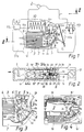
- zeigt vereinfacht einen Leitungsschutzschalter mit im Bereich der Löschkammer geöffneter oberer Gehäuseschale, während in
- Fig. 2
- ein Schnitt durch die Löschkammer gemäß Linie II-II der Fig. 1 wiedergegeben ist. In
- Fig. 3
- ist in einer perspektivischen Ansicht der erfindungswesentliche Löschkammerbereich einer Gehäusehalbschale gezeigt, während
- Fig. 4
- in einer schematisierten Explosivdarstellung die Innenkonturen der beiden voneinander getrennten Gehäusehalbschalen im Bereich der Löschkammer zeigt.
- Fig. 1
- shows simplified a circuit breaker with the upper housing shell open in the area of the arcing chamber, while in
- Fig. 2
- a section through the arcing chamber according to line II-II of FIG. 1 is shown. In
- Fig. 3
- is shown in a perspective view of the quench chamber region essential to the invention of a housing half-shell, while
- Fig. 4
- shows a schematic exploded view of the inner contours of the two separate housing shells in the area of the arcing chamber.
Der Leitungsschutzschalter in Schmalbauweise hat ein aus zwei Gehäuseschalen (1a, 1b) zusammengesetztes Gehäuse (1), das im oberen Teil einen lediglich angedeuteten Schalt- und Auslösemechanismus (2) aufnimmt. Im darunter befindlichen Sockelbereich ist das aus duroplastischer oder thermoplastischer Formmasse hergestellte Gehäuse (1) überwiegend als Löschkammer (3) ausgebildet, die größtenteils mit einem parallel zur Bodenfläche (1c) des Schalters angeordneten Löschblechstapel (4) ausgefüllt ist. Die Tiefe der Löschkammer zwischen ihren bei den inneren Seitenflächen (3a, 3b) ist dabei ausgehend von der standardisierten Schalterbreite durch Gehäuseaußenwände (1a′, 1b′) in herstellungstechnisch üblicher Wanddicke vorbestimmt.The narrow circuit breaker has a housing (1) composed of two housing shells (1a, 1b), which accommodates a switching and release mechanism (2), which is only indicated, in the upper part. In the base area underneath, the housing (1) made of thermosetting or thermoplastic molding compound is predominantly designed as an extinguishing chamber (3), which is largely filled with an extinguishing sheet stack (4) arranged parallel to the bottom surface (1c) of the switch. The depth of the Extinguishing chamber between their at the inner side surfaces (3a, 3b) is predetermined, based on the standardized switch width, by the outer walls of the housing (1a ', 1b') in the wall thickness that is customary in terms of production technology.
Der in die Löschkammer eingelegte, mit seinen linksseitigen schmalen Stirnflächen an einer mit Ausblasöffnungen versehenen Gehäusewand (1d) anliegende Löschblechstapel (4) ist jeweils auf seiner oberen und unteren Längsseite durch Lichtbogenlaufschienen (6) bzw. (7) begrenzt, die ihrerseits in den Bereich einer im Vorkammerraum (3c) der Löschkammer befindlichen Kontaktanordnung (5) gerichtet sind. Mit beispielsweise neun nebeneinander auf Abstand angeordneten Löschblechen (4a) aus ferromagnetischem Werkstoff füllt der Löschblechstapel zwischen beiden inneren Seitenflächen (3a, 3b) den kastenförmigen Teil der Löschkammer seitlich des Vorkammerraumes (3c) völlig aus und ist dort in nicht näher dargestellter Weise unverrückbar gehalten.The stack of quenching plates (4) inserted into the quenching chamber, with its narrow end faces on the left-hand side against a housing wall (1d) provided with blow-out openings, is delimited on its upper and lower longitudinal sides by arc guiding rails (6) and (7), which in turn are in the area a contact arrangement (5) located in the prechamber space (3c) of the arcing chamber. With, for example, nine quenching plates (4a) made of ferromagnetic material arranged next to one another at a distance, the stack of quenching plates between the two inner side surfaces (3a, 3b) completely fills the box-shaped part of the quenching chamber to the side of the prechamber space (3c) and is held there immovably in a manner not shown in detail.
Die am rechten oberen Rand der Löschkammer im etwa trichterförmigen Vorkammerraum (3c) angeordnete Kontaktstelle mit Einfachunterbrechung besteht aus einem Festkontaktstück (5a) welches über Stromführungsteile (10a) und eine Auslösespule (10) mit einer Ausgangsklemme (11) verbunden ist, und einem um eine gehäusefeste Achse schwenkbaren Kontakthebel (5b). Dieser steht über bewegliche Leitungen (12a, 12b) unter Einbindung eines thermischen Auslösers (12) mit einer Eingangsklemme (13) in Verbindung und schwenkt bei einem Abschaltvorgang im Gegenuhrzeigersinn. Festkontaktstück (5a) und Kontakthebel (5b) bilden an der eigentlichen Kontaktberührungsstelle zusammen mit ihren Stromzuleitungen eine etwa U-förmige Stromschleife, die senkrecht zur Richtung der Löschbleche (4a) orientiert ist. Die einzelnen Löschbleche haben an ihrer dem Vorkammerraum (3c) zugekehrten Stirnseite einen den Lichtbogeneinlauf verbessernden, etwa V-förmigen Einschnitt (4b) und decken mit der so gebildeten Stirnkontur den gesamten offenen Querschnitt des zu den übrigen Gehäusebereichen überwiegend durch Wandteile (1e) umschlossenen Vorkammerraumes ab. Lediglich eine für die Schwenkbewegung des Kontakthebels (5b) erforderliche Ausnehmung ist in den Wandteilen (1e) ausgespart, so daß der Vorkammerraum (3c) in Verbindung mit den Lichtbogenleitschienen (6, 7) zum Schalt- und Auslösemechanismus hin nahezu druckdicht ausgebildet ist.The contact point with a single break in the funnel-shaped prechamber space (3c) on the right upper edge of the quenching chamber consists of a fixed contact piece (5a) which is connected to an output terminal (11) via current-carrying parts (10a) and a trigger coil (10), and one by one Fixed axis swiveling contact lever (5b). This is connected to an input terminal (13) via movable lines (12a, 12b) with the inclusion of a thermal release (12) and pivots counterclockwise when it is switched off. Fixed contact piece (5a) and contact lever (5b) form an approximately U-shaped current loop at the actual contact point of contact together with their current leads. which is oriented perpendicular to the direction of the extinguishing plates (4a). The individual quenching plates have an approximately V-shaped incision (4b) on their front side facing the pre-chamber space (3c) and improve the arc run-in and cover the entire open cross-section of the pre-chamber space, which is mainly enclosed by wall parts (1e), with the front contour formed in this way from. Only a recess required for the pivoting movement of the contact lever (5b) is recessed in the wall parts (1e), so that the prechamber space (3c) in connection with the arc guide rails (6, 7) is designed to be almost pressure-tight to the switching and triggering mechanism.
Von wesentlicher Bedeutung sind jeweils zwei im Vorkammerraum (3c) auf beiden Seitenflächen (3a, 3b) zur Gehäusemitte prismatisch vorstehende, schmale Stege (3d, 3e), die im Normalfall einen Rechteckquerschnitt aufweisen, aber auch trapezförmig oder stufenförmig ausgebildet sein können. Sie sind direkt an beiden Gehäuseschalen (1a, 1b) vom Grund der Außenwände (1a′, 1b′) bis etwa zur Schwenkebene des beweglichen Kontakthebels (5b) angeformt und enden mit ihrer Oberseite vorzugsweise in gleichhohem Abstand von den Seitenflächen. In Löschkammerebene, d. h. in Zeichnungsebene der Fig. 1, verlaufen die etwa gleichmäßig breiten Stege (3d, 3e) jedoch in unterschiedlicher Bogenform, und zwar vom Bereich der Kontaktanordnung bis zur Stirnkontur des Löschblechstapels.Of essential importance are two narrow webs (3d, 3e) that protrude prismatically on both side surfaces (3a, 3b) towards the center of the housing in the prechamber space (3c), which normally have a rectangular cross-section, but can also be trapezoidal or step-shaped. They are formed directly on both housing shells (1a, 1b) from the bottom of the outer walls (1a ', 1b') to about the pivoting plane of the movable contact lever (5b) and preferably end at the same distance from the side surfaces. At the extinguishing chamber level, i.e. H. 1, the approximately uniformly wide webs (3d, 3e), however, run in different arc shapes, namely from the area of the contact arrangement to the end contour of the stack of quenching plates.
Dabei liegt der obere Steg (3d) am Festkontaktstück (5a) eng an und folgt dessen Kontakthorn (5a′) auf der dem Vorkammerraum zugekehrten Seite bis an die Löschkammerwand im Bereich der oberen Lichtbogenlaufschiene (6). Zusammen umfassen die Stege (3d) beider Gehäuseschalen das Festkontaktstück an der Kontaktseite sowie auf beiden Schmalseiten derart, daß in der Mitte zwischen den Stegen (3d) praktisch nur ein Spalt entsprechend der Breite des Kontakthebels (5b) entlang des Lichtbogenhorns (5a′) freibleibt.The upper web (3d) is tight on the fixed contact piece (5a) and follows its contact horn (5a ') on the side facing the prechamber space up to the quenching chamber wall in the area of the upper arc runner (6). Together they include Crosspieces (3d) of both housing shells the fixed contact piece on the contact side and on both narrow sides such that in the middle between the crosspieces (3d) practically only a gap corresponding to the width of the contact lever (5b) remains free along the arcing horn (5a ').
Vergleichbares gilt für den Steg (3e) entlang der unteren Lichtbogenlaufschiene (7). Diese ist ebenfalls an den Längskanten zum Vorkammerraum (3c) hin beiderseits durch Stege (3e) eng eingefaßt, so daß auch hier nur ein etwa kontakthebelbreiter Spalt freibleibt, der zur Fußpunktbildung des Schaltlichtbogens (9) dient. Durch die Oberseiten der Stege (3d, 3e) eingeengt kann so der Lichtbogen innerhalb des Spaltes in den Löschblechstapel einlaufen. Eine geringfügig vorstehende Sicke (7′) auf der unteren Lichtbogenlaufschiene in Nähe des Spaltes unterstützt die geradlinige Laufrichtung des Lichtbogenfußpunktes zusätzlich. Positiv beeinflußt wird der Antrieb des Lichtbogens außerdem von den durch die Stege (3e) seitlich verdeckten Teilen der breiteren, ferromagnetischen Lichtbogenlaufschiene (7), da der größere Materialquerschnitt die lichtbogenantreibende Wirkung verbessert.The same applies to the web (3e) along the lower arc runner (7). This is also closely bordered on the longitudinal edges to the prechamber space (3c) on both sides by webs (3e), so that here too there is only a gap, approximately the width of a contact lever, which serves to form the base of the switching arc (9). Constricted through the tops of the webs (3d, 3e), the arc can thus enter the stack of quenching plates within the gap. A slightly protruding bead (7 ') on the lower arc runner near the gap additionally supports the straight running direction of the arc base. The arc drive is also positively influenced by the parts of the wider, ferromagnetic arc guide rail (7) which are laterally hidden by the webs (3e), since the larger material cross section improves the arc driving effect.
Ein weiteres Hauptmerkmal der Erfindung sind mehrere im Vorkammerraum (3c) angeordnete Säulen oder auch Zapfen (3f) - weiterhin nur als Säulen bezeichnet - die im freien Querschnitt zwischen den Stegen (3d, 3e) etwa gleichmäßig verteilt angeordnet sind. Die im Querschnitt runden oder auch eckigen Säulen (3f) haben dabei zu den Stegen (3d, 3e) sowie untereinander einen etwa gleichgroßen Abstand und reichen jeweils von den Seitenflächen (3a, 3b) bis nahezu an die Schwenkebene des Kontakthebels (5b), so daß lediglich ein schmaler Spalt zwischen ihren Stirnflächen (3f′) durchgehend freibleibt. Die Stirnflächen beider Säulengruppen flankieren dadurch einen an der Kontaktstelle gezogenen Schaltlichtbogen (9) in Verbindung mit den vorzugsweise gleichhohen Stegen (3d, 3e) seitlich eng, während seine Fußpunkte auf dem Kontakthorn (5a′) sowie den Lichtbogenlaufschienen (6, 7) auseinandergezogen und aus dem Kontaktbereich in Richtung des Löschblechstapels (4) beschleunigt angetrieben werden. (Lichtbogenpos. 9′,9˝)Another main feature of the invention is a plurality of columns or pins (3f) arranged in the prechamber space (3c) - still referred to only as columns - which are arranged approximately evenly distributed in the free cross section between the webs (3d, 3e). The columns (3f), which are round or square in cross-section, have an approximately equal distance from the webs (3d, 3e) and from one another and each extend from the side surfaces (3a, 3b) to almost the pivoting plane of the contact lever (5b), see above that only a narrow gap between their end faces (3f ') continuously remains free. The end faces of both groups of columns flank a switching arc (9) drawn at the contact point in conjunction with the preferably equally high webs (3d, 3e), while its base points on the contact horn (5a ') and the arc guide rails (6, 7) are pulled apart and are accelerated from the contact area in the direction of the stack of quenching plates (4). (Arc pos. 9 ′, 9˝)
Die Säulen (3f) sind vorzugsweise in einem leichten Zickzackversatz zu einer mittleren Ideallinie zwischen den beiden Stegen (3d, 3e) vom Kontaktstellenbereich in Richtung der Löschblechstirnseiten angeordnet, können aber auch direkt in Reihe auf dieser Ideallinie angeordnet sein. Lediglich in dem sich trichterförmig erweiternden Bereich direkt vor den Löschblechen (4a) sind idealerweise zwei Säulen angeordnet (Fig. 1, Fig. 3). Auf jeder Gehäusehalbschale (1a, 1b) sind gemäß Ausführungsbeispiel sieben Säulen (3f) unmittelbar bei der Herstellung der Gehäuseteile mit angeformt, wobei die Säulen bevorzugt leicht kegelstumpfförmig mit einem mittleren Durchmesser von etwa 2 mm und einer Höhe von etwa 6 mm ausgebildet sind. Da bei Leitungsschutzschaltern aufgrund der Form der Kontaktanordnung und ihrer Lage zu den Lichtbogenlaufschienen einerseits sowie der Anzahl der Löschbleche und ihrer Anordnung in der Löschkammer andererseits verschiedene technisch sinnvolle Lösungen für die Gestaltung des Vorkammerraumes möglich sind, ist die Anordnung der Säulen (3f) von den genannten Kriterien mit abhängig. Die Anzahl der Säulen auf jedem Gehäuseteil wird dabei im wesentlichen von der Größe des Vorkammerraumes abhängen, während sie in ihrer Lage möglichst gleichmäßig verteilt zwischen dem Kontaktstellenbereich und den Löschblechstirnseiten angeordnet sein sollten. Idealerweise sind die Säulengruppen in den beiden Gehäusehalbschalen jeweils auf Lücke versetzt angeordnet, wie insbesondere in Fig. 2 angedeutet ist. So wird trotz enger Führung des Schaltlichtbogens (9) die auf ihn wirkende Reibung durch die Säulen (3f) vermindert, da praktisch beim Ablaufen des Lichtbogens jeweils nur eine Stirnfleche der beiden Säulengruppen im Wechsel wirksam ist.The columns (3f) are preferably arranged in a slight zigzag offset to a middle ideal line between the two webs (3d, 3e) from the contact area in the direction of the fire-extinguishing sheet end faces, but can also be arranged directly in a row on this ideal line. Ideally, only two columns are arranged in the funnel-shaped area directly in front of the quenching plates (4a) (FIG. 1, FIG. 3). According to the exemplary embodiment, seven columns (3f) are formed on each housing half-shell (1a, 1b) directly during the manufacture of the housing parts, the columns preferably being slightly frustoconical in shape with an average diameter of approximately 2 mm and a height of approximately 6 mm. Since in line circuit breakers due to the shape of the contact arrangement and their position to the arc guide rails on the one hand and the number of quenching plates and their arrangement in the quenching chamber on the other hand, various technically sensible solutions for the design of the prechamber space are possible, the arrangement of the columns (3f) is of the named ones Criteria with dependent. The number of pillars on each housing part will essentially depend on the size of the prechamber space, while their position should be distributed as evenly as possible between the contact point area and the quenching plate end faces. Ideally, the column groups are in the two housing shells arranged offset to a gap, as indicated in particular in FIG. 2. Thus, despite close guidance of the switching arc (9), the friction on it by the columns (3f) is reduced, since practically only one end face of the two groups of columns is effective in alternation when the arc runs off.
Unabhängig von Anzahl, Größe und Lage der Säulen nehmen diese etwa eine Grundfläche zwischen 5 und 15 % der zwischen den Stegen (3d, 3e) verbleibenden Fläche des Vorkammerraumes ein, so daß um die Säulen (3f) Strömungskanäle (8) offenbleiben, die von den als Abdichtungswände wirkenden Stegen und Wandteilen (3d, 3e, 1e) zum übrigen Schalter hin abgeschottet sind. Aufgrund des geringen Volumens der Säulen (3f) im Verhältnis zum gesamten Vorkammerraum ergibt sich somit ein optimal großer Gasexpansionsraum, obwohl der Lichtbogen eng geführt und daher seine Stromdichte möglichst groß gehalten wird. Der daraus resultierende hohe elektrodynamische Antrieb sowie die praktisch vernachlässigbare Reibung an den Stirnflächen der Säulen bewirken einen sicheren und schnellen Ablauf des Schaltlichtbogens von der Kontaktstelle in den Löschblechstapel. Der vorhandene Expansionsraum und die Strömungskanäle um die Säulen sorgen zugleich für einen geringeren Gasdruck, der wiederum die Ionenkonzentration herabsetzt und die Gefahr von Neuzündungen hinter dem Lichtbogen eindämmt. Als eine Art Puffer sowie als kühlende Luftmassenreserve kann dabei der Raum hinter dem Festkontaktstück (5a) dienen, wenn der das Kontakthorn bis zur oberen Lichtbogenlaufschiene (6) einfassende Steg (3d) etwa mit der Oberseite der Kontaktstelle endet - Dadurch verbleibt zwischen dem Ende des Steges (3d) und dem Wandteil (1e) ein Querströmungskanal (8′), der einen Druckausgleich oberhalb der Kontaktstelle zum eigentlichen Vorkammerraum (3c) hin ermöglicht.Regardless of the number, size and position of the columns, these take up approximately a base area between 5 and 15% of the area of the prechamber space remaining between the webs (3d, 3e), so that flow channels (8) remain open around the columns (3f) the webs and wall parts (3d, 3e, 1e) acting as sealing walls are sealed off from the rest of the switch. Due to the small volume of the columns (3f) in relation to the entire prechamber space, this results in an optimally large gas expansion space, although the arc is guided closely and therefore its current density is kept as large as possible. The resulting high electrodynamic drive and the practically negligible friction on the end faces of the pillars ensure that the switching arc runs safely and quickly from the contact point into the stack of quenching plates. The existing expansion space and the flow channels around the columns also ensure a lower gas pressure, which in turn reduces the ion concentration and reduces the risk of reignitions behind the arc. The space behind the fixed contact piece (5a) can serve as a kind of buffer and as a cooling air mass reserve, if the web (3d) that surrounds the contact horn up to the upper arc runner (6) ends approximately with the top of the contact point - this leaves between the end of the contact point Web (3d) and the wall part (1e) a cross-flow channel (8 '), which enables pressure equalization above the contact point to the actual antechamber (3c).
Die vorbeschriebene und in den Zeichnungsfiguren dargestellte Anordnung der Säulen sowie die gesamte Gestaltung des Vorkammerraumes für einen Leitungsschutzschalter kann unter Berücksichtigung der genannten Kriterien ebenso für andere Selbstschalter Verwendung finden. Hierbei wird der Fachmann die Säulen und Stege an die räumlichen Abmessungen der Löschkammer und des Vorkammerraumes im Einzelfall anpassen müssen, ohne den Rahmen der Ansprüche zu verlassen.The arrangement of the columns described above and shown in the drawing figures as well as the entire design of the prechamber space for a circuit breaker can also be used for other circuit breakers, taking into account the criteria mentioned. In this case, the person skilled in the art will have to adapt the columns and webs to the spatial dimensions of the arcing chamber and the prechamber space in individual cases without leaving the scope of the claims.
Claims (15)
- Automatic switch with a housing (1), which is made of insulating material and receives the switching mechanism (2), and with a quenching chamber (3), which is enclosed by the housing and displays an antechamber space (3c), which flanks the contact arrangement (5) and has arc guide means (3f), which are integrated in the housing and project therefrom, for the running of the switching arc (9, 9′, 9") from the contact point into an arc quenching region, in particular a quenching plate stack (4), which in its turn closes off the antechamber space (3c), which enlarges in funnel shape from the contact arrangement (5) to the quenching plates (4) and is provided with arcing horns (5a′, 6, 7), at the side remote from the contact point, characterised thereby, that webs (3d, 3e) of insulating material, which begin at about the contact arrangement (5) and from there lie against along the arcing horns (5a′, 6, 7) and which enclose the arcing horns (5a′, 6, 7) towards the antechamber space (3c) except for a gap in the contact opening plane and at the same time form sealing walls towards the switching mechanism (2), are arranged in the antechamber space (3c) on at least one side surface of the inward side surfaces (3a, 3b) of the housing (1), which are situated about parallelly to the plane of the contact opening movement of the contact lever (5b), and that several pillars or spigots (3f), which project from the base of the side surfaces (3a, 3b) in the direction of the contact opening plane, are arranged in the remaining flow channel (8) of the antechamber space (3c) between the sealing walls (3d, 3e; 1e) to be approximately uniformly distributed approximately in such a manner that, by their end faces (3f′) and in co-operation with the webs (3d, 3e), they effect a close lateral guidance of the switching arc (9) with small contact area and that, in spite of the close guidance, a large gas expansion chamber remains between the pillars or spigots (3f).
- Switch according to claim 1, characterised thereby, that the pillars (3f) are arranged to be distributed between the sealing walls (3d, 3e; 1e) as well as one among the other in such a manner within the flow channel (8) that notional circles of about equal diameter about their foot points are one adjacent to the other as well as each tangent at the circumference to the sealing walls.
- Switch according to one of the claims 1 to 2, characterised thereby, that the pillars (3f) are arranged at approximate equal spacing one behind the other at points in a row.
- Switch according to one of the claims 1 to 3, characterised thereby, that the pillars (3f) are arranged with their foot points on an ideal arc line in about the middle between the arcuately extending webs (3d, 3e).
- Switch according to one of the claims 1 to 3, characterised thereby, that the pillars (3f) are arranged with their foot points almost uniformly distributed between the webs (3d, 3e) in the flow channel (8) in the manner of a zig-zag line on the side surfaces (3a, 3b).
- Switch according to one of the claims 1 to 5, characterised thereby, that the pillars (3f) of the one side surface (3a) are each arranged to be staggered opposite gaps between those on the other side surface (3b) of the housing (1).
- Switch according to one of the claims 1 to 6, characterised thereby, that the pillars (3f) of one side surface (3a or 3b) are each formed to be equal in height with the associated webs (3d, 3e) and display end faces (3f′) situated in one plane.
- Switch according to one of the claims 1 to 7, characterised thereby, that the webs (3d, 3e) and also the pillars (3f) are shaped on directly in the manufacture of the housing parts (1a, 1b).
- Switch according to one of the claims 1 to 8, characterised thereby, that preferably between five and nine pillars (3f) are arranged on each side surface (3a or 3b) within the antechamber space (3c).
- Switch according to one of the claims 1 to 9, characterised thereby, that about 5 to 15% of the total area of the flow channel (8) between the sealing walls (webs 3d, 3e; wall parts 1e) is covered by the base area of the pillars (3f).
- Switch according to one of the claims 1 to 10, characterised thereby, that the pillars (3f) are formed to be round or also cornered and display a diameter or a side length of about 2 millimetres.
- Switch according to one of the claims 1 to 11, characterised thereby, that the pillars (3f) each display a height of approximately 6 millimetres at both sides of the contact opening plane.
- Switch according to one of the claims 1 to 12, characterised thereby, that the pillars (3f) are shaped to narrow with a conical taper of about 10° in the direction of the contact opening plane.
- Switch according to one of the claims 1 to 13, characterised thereby, that the gap between the end faces (3f′) of the pillars (3f) or the upper sides of the webs (3d, 3e) of both half shells (1a, 1b) of the housing (1) displays a width of approximately 3 millimetres.
- Switch according to one of the claims 1 to 14, characterised thereby, that the webs (3d, 3e) are formed for the positioning and retention of the fixed contact member (5a) together with contact horn (5a′) on the one hand and the lower arcing horn (7) on the other hand.
Applications Claiming Priority (4)
| Application Number | Priority Date | Filing Date | Title |
|---|---|---|---|
| DE3908102 | 1989-03-13 | ||
| DE19893908102 DE3908102A1 (en) | 1989-03-13 | 1989-03-13 | Automatic circuit breaker, especially a line protective circuit breaker |
| DE19904007606 DE4007606A1 (en) | 1990-03-09 | 1990-03-09 | Automatic load protection switch |
| DE4007606 | 1990-03-09 |
Publications (3)
| Publication Number | Publication Date |
|---|---|
| EP0387761A2 EP0387761A2 (en) | 1990-09-19 |
| EP0387761A3 EP0387761A3 (en) | 1992-01-29 |
| EP0387761B1 true EP0387761B1 (en) | 1994-12-14 |
Family
ID=25878766
Family Applications (1)
| Application Number | Title | Priority Date | Filing Date |
|---|---|---|---|
| EP90104653A Expired - Lifetime EP0387761B1 (en) | 1989-03-13 | 1990-03-12 | Automatic circuit breaker, particularly automatic cut-out |
Country Status (5)
| Country | Link |
|---|---|
| EP (1) | EP0387761B1 (en) |
| AT (1) | ATE115767T1 (en) |
| DE (1) | DE59007970D1 (en) |
| ES (1) | ES2065420T3 (en) |
| HK (1) | HK64895A (en) |
Cited By (1)
| Publication number | Priority date | Publication date | Assignee | Title |
|---|---|---|---|---|
| DE19860427A1 (en) * | 1998-12-28 | 2000-06-29 | Abb Patent Gmbh | Electrical switching device, in particular circuit breakers |
Families Citing this family (4)
| Publication number | Priority date | Publication date | Assignee | Title |
|---|---|---|---|---|
| CN103441049B (en) * | 2013-09-06 | 2015-07-22 | 浙江大华电气有限公司 | Arc ignition structure reinforcing self-excitation magnetic field intensity |
| WO2015151393A1 (en) * | 2014-03-31 | 2015-10-08 | パナソニックIpマネジメント株式会社 | Circuit breaker |
| CN105185671B (en) * | 2015-10-30 | 2019-06-25 | 上海电科电器科技有限公司 | Breaker and its baffle |
| CN106783294B (en) * | 2016-11-30 | 2018-08-24 | 陶如意 | A kind of mechanical extruding type arc-extinguishing mechanism of power circuit breaker |
Family Cites Families (4)
| Publication number | Priority date | Publication date | Assignee | Title |
|---|---|---|---|---|
| DE3413555A1 (en) * | 1984-04-11 | 1985-10-24 | Brown, Boveri & Cie Ag, 6800 Mannheim | DELETING DEVICE FOR ELECTRICAL SWITCHES |
| FR2575861B1 (en) * | 1985-01-07 | 1987-01-16 | Merlin Gerin | MINIATURE ELECTRIC CIRCUIT BREAKER WITH ARC FORMING CHAMBER |
| DE3619241C2 (en) * | 1986-06-07 | 1994-07-21 | Kloeckner Moeller Gmbh | Extinguishing device for a circuit breaker |
| DE3621690A1 (en) * | 1986-06-27 | 1988-01-14 | Bbc Brown Boveri & Cie | DELETING DEVICE FOR ELECTRICAL SWITCHES |
-
1990
- 1990-03-12 DE DE59007970T patent/DE59007970D1/en not_active Expired - Fee Related
- 1990-03-12 ES ES90104653T patent/ES2065420T3/en not_active Expired - Lifetime
- 1990-03-12 AT AT90104653T patent/ATE115767T1/en not_active IP Right Cessation
- 1990-03-12 EP EP90104653A patent/EP0387761B1/en not_active Expired - Lifetime
-
1995
- 1995-04-27 HK HK64895A patent/HK64895A/en not_active IP Right Cessation
Cited By (2)
| Publication number | Priority date | Publication date | Assignee | Title |
|---|---|---|---|---|
| DE19860427A1 (en) * | 1998-12-28 | 2000-06-29 | Abb Patent Gmbh | Electrical switching device, in particular circuit breakers |
| DE19860427B4 (en) * | 1998-12-28 | 2006-08-03 | Abb Patent Gmbh | Electrical switching device, in particular circuit breaker |
Also Published As
| Publication number | Publication date |
|---|---|
| ATE115767T1 (en) | 1994-12-15 |
| EP0387761A3 (en) | 1992-01-29 |
| HK64895A (en) | 1995-05-05 |
| DE59007970D1 (en) | 1995-01-26 |
| ES2065420T3 (en) | 1995-02-16 |
| EP0387761A2 (en) | 1990-09-19 |
Similar Documents
| Publication | Publication Date | Title |
|---|---|---|
| DE919722C (en) | Electric circuit breaker | |
| EP0752153B2 (en) | Arc quenching chamber with three barriers for the passage of arc gasses | |
| DE3619241C2 (en) | Extinguishing device for a circuit breaker | |
| EP0387761B1 (en) | Automatic circuit breaker, particularly automatic cut-out | |
| DE3908102A1 (en) | Automatic circuit breaker, especially a line protective circuit breaker | |
| DE4007606A1 (en) | Automatic load protection switch | |
| DE1063246B (en) | Arc extinguishing chamber for switches with high breaking capacity | |
| DE1415944B2 (en) | ||
| DE969297C (en) | Electrical disconnector | |
| DE19860427B4 (en) | Electrical switching device, in particular circuit breaker | |
| EP0183145B1 (en) | Electrical switch device, especially a protective power circuit breaker | |
| DE1005153B (en) | Arc extinguishing device for electrical switches | |
| EP0051756B1 (en) | Arc extinguishing device, in particular for an automatic cut out | |
| DE2916368C2 (en) | Cathode for a gas discharge display device | |
| DE2816352C2 (en) | Low voltage circuit breaker with arcing compartment and switching mechanism | |
| DE3621165A1 (en) | ARC EXTINGUISHING DEVICE | |
| DE1790089C3 (en) | ||
| DE2741868C2 (en) | Arc chamber with arc rails and perforated ceramic plates | |
| DE2949012A1 (en) | ARC CHAMBER OF A CIRCUIT BREAKER | |
| DE1027280B (en) | Circuit breaker with a shaft for receiving and extinguishing the switching arc | |
| DE1926355B1 (en) | Arc extinguishing chamber for low-voltage circuit breakers | |
| DE19643643B4 (en) | Circuit breaker with arc extinguishing chamber and deionization | |
| AT404770B (en) | ARC EXTINGUISHING CHAMBER FOR SWITCHES | |
| DE1415944C (en) | Circuit breakers, in particular installation circuit breakers | |
| EP0231733A2 (en) | Arc quenching chamber |
Legal Events
| Date | Code | Title | Description |
|---|---|---|---|
| PUAI | Public reference made under article 153(3) epc to a published international application that has entered the european phase |
Free format text: ORIGINAL CODE: 0009012 |
|
| AK | Designated contracting states |
Kind code of ref document: A2 Designated state(s): AT BE CH DE ES FR GB GR IT LI NL |
|
| PUAL | Search report despatched |
Free format text: ORIGINAL CODE: 0009013 |
|
| AK | Designated contracting states |
Kind code of ref document: A3 Designated state(s): AT BE CH DE ES FR GB GR IT LI NL |
|
| 17P | Request for examination filed |
Effective date: 19920129 |
|
| 17Q | First examination report despatched |
Effective date: 19940322 |
|
| GRAA | (expected) grant |
Free format text: ORIGINAL CODE: 0009210 |
|
| AK | Designated contracting states |
Kind code of ref document: B1 Designated state(s): AT BE CH DE ES FR GB GR IT LI NL |
|
| REF | Corresponds to: |
Ref document number: 115767 Country of ref document: AT Date of ref document: 19941215 Kind code of ref document: T |
|
| REF | Corresponds to: |
Ref document number: 59007970 Country of ref document: DE Date of ref document: 19950126 |
|
| GBT | Gb: translation of ep patent filed (gb section 77(6)(a)/1977) |
Effective date: 19950110 |
|
| REG | Reference to a national code |
Ref country code: ES Ref legal event code: FG2A Ref document number: 2065420 Country of ref document: ES Kind code of ref document: T3 |
|
| ET | Fr: translation filed | ||
| ITF | It: translation for a ep patent filed |
Owner name: MODIANO & ASSOCIATI S.R.L. |
|
| REG | Reference to a national code |
Ref country code: GR Ref legal event code: FG4A Free format text: 3014652 |
|
| PLBE | No opposition filed within time limit |
Free format text: ORIGINAL CODE: 0009261 |
|
| STAA | Information on the status of an ep patent application or granted ep patent |
Free format text: STATUS: NO OPPOSITION FILED WITHIN TIME LIMIT |
|
| 26N | No opposition filed | ||
| REG | Reference to a national code |
Ref country code: CH Ref legal event code: PUE Owner name: LICENTIA PATENT- VERWALTUNGS-GMBH TRANSFER- AEG NI |
|
| REG | Reference to a national code |
Ref country code: GB Ref legal event code: 732E |
|
| NLS | Nl: assignments of ep-patents |
Owner name: AEG NIEDERSPANNUNGSTECHNIK GMBH & CO. KG |
|
| REG | Reference to a national code |
Ref country code: FR Ref legal event code: TP |
|
| REG | Reference to a national code |
Ref country code: ES Ref legal event code: PC2A |
|
| REG | Reference to a national code |
Ref country code: GB Ref legal event code: IF02 |
|
| PGFP | Annual fee paid to national office [announced via postgrant information from national office to epo] |
Ref country code: GR Payment date: 20060227 Year of fee payment: 17 |
|
| PGFP | Annual fee paid to national office [announced via postgrant information from national office to epo] |
Ref country code: NL Payment date: 20060321 Year of fee payment: 17 Ref country code: AT Payment date: 20060321 Year of fee payment: 17 |
|
| PGFP | Annual fee paid to national office [announced via postgrant information from national office to epo] |
Ref country code: GB Payment date: 20060322 Year of fee payment: 17 |
|
| PGFP | Annual fee paid to national office [announced via postgrant information from national office to epo] |
Ref country code: CH Payment date: 20060406 Year of fee payment: 17 |
|
| PGFP | Annual fee paid to national office [announced via postgrant information from national office to epo] |
Ref country code: DE Payment date: 20060929 Year of fee payment: 17 |
|
| REG | Reference to a national code |
Ref country code: CH Ref legal event code: PL |
|
| PG25 | Lapsed in a contracting state [announced via postgrant information from national office to epo] |
Ref country code: AT Free format text: LAPSE BECAUSE OF NON-PAYMENT OF DUE FEES Effective date: 20070312 |
|
| GBPC | Gb: european patent ceased through non-payment of renewal fee |
Effective date: 20070312 |
|
| NLV4 | Nl: lapsed or anulled due to non-payment of the annual fee |
Effective date: 20071001 |
|
| PG25 | Lapsed in a contracting state [announced via postgrant information from national office to epo] |
Ref country code: DE Free format text: LAPSE BECAUSE OF NON-PAYMENT OF DUE FEES Effective date: 20071002 Ref country code: NL Free format text: LAPSE BECAUSE OF NON-PAYMENT OF DUE FEES Effective date: 20071001 |
|
| PG25 | Lapsed in a contracting state [announced via postgrant information from national office to epo] |
Ref country code: LI Free format text: LAPSE BECAUSE OF NON-PAYMENT OF DUE FEES Effective date: 20070331 Ref country code: CH Free format text: LAPSE BECAUSE OF NON-PAYMENT OF DUE FEES Effective date: 20070331 |
|
| PG25 | Lapsed in a contracting state [announced via postgrant information from national office to epo] |
Ref country code: GB Free format text: LAPSE BECAUSE OF NON-PAYMENT OF DUE FEES Effective date: 20070312 |
|
| PG25 | Lapsed in a contracting state [announced via postgrant information from national office to epo] |
Ref country code: GR Free format text: LAPSE BECAUSE OF NON-PAYMENT OF DUE FEES Effective date: 20071003 |
|
| PGFP | Annual fee paid to national office [announced via postgrant information from national office to epo] |
Ref country code: ES Payment date: 20090326 Year of fee payment: 20 |
|
| PGFP | Annual fee paid to national office [announced via postgrant information from national office to epo] |
Ref country code: IT Payment date: 20090331 Year of fee payment: 20 |
|
| PGFP | Annual fee paid to national office [announced via postgrant information from national office to epo] |
Ref country code: BE Payment date: 20090430 Year of fee payment: 20 |
|
| PGFP | Annual fee paid to national office [announced via postgrant information from national office to epo] |
Ref country code: FR Payment date: 20090317 Year of fee payment: 20 |
|
| BE20 | Be: patent expired |
Owner name: *AEG NIEDERSPANNUNGSTECHNIK G.M.B.H. & CO. K.G. Effective date: 20100312 |
|
| REG | Reference to a national code |
Ref country code: ES Ref legal event code: FD2A Effective date: 20100313 |
|
| PG25 | Lapsed in a contracting state [announced via postgrant information from national office to epo] |
Ref country code: ES Free format text: LAPSE BECAUSE OF EXPIRATION OF PROTECTION Effective date: 20100313 |