EP0387514A2 - Absperrvorrichtung für Schüttgut-Transportleitungen - Google Patents
Absperrvorrichtung für Schüttgut-Transportleitungen Download PDFInfo
- Publication number
- EP0387514A2 EP0387514A2 EP90101866A EP90101866A EP0387514A2 EP 0387514 A2 EP0387514 A2 EP 0387514A2 EP 90101866 A EP90101866 A EP 90101866A EP 90101866 A EP90101866 A EP 90101866A EP 0387514 A2 EP0387514 A2 EP 0387514A2
- Authority
- EP
- European Patent Office
- Prior art keywords
- support
- cap
- seal
- piston
- housing
- Prior art date
- Legal status (The legal status is an assumption and is not a legal conclusion. Google has not performed a legal analysis and makes no representation as to the accuracy of the status listed.)
- Withdrawn
Links
Images


Classifications
-
- F—MECHANICAL ENGINEERING; LIGHTING; HEATING; WEAPONS; BLASTING
- F16—ENGINEERING ELEMENTS AND UNITS; GENERAL MEASURES FOR PRODUCING AND MAINTAINING EFFECTIVE FUNCTIONING OF MACHINES OR INSTALLATIONS; THERMAL INSULATION IN GENERAL
- F16K—VALVES; TAPS; COCKS; ACTUATING-FLOATS; DEVICES FOR VENTING OR AERATING
- F16K5/00—Plug valves; Taps or cocks comprising only cut-off apparatus having at least one of the sealing faces shaped as a more or less complete surface of a solid of revolution, the opening and closing movement being predominantly rotary
- F16K5/08—Details
- F16K5/14—Special arrangements for separating the sealing faces or for pressing them together
- F16K5/20—Special arrangements for separating the sealing faces or for pressing them together for plugs with spherical surfaces
- F16K5/204—Special arrangements for separating the sealing faces or for pressing them together for plugs with spherical surfaces with the plugs or parts of the plugs mechanically pressing the seals against the housing
-
- F—MECHANICAL ENGINEERING; LIGHTING; HEATING; WEAPONS; BLASTING
- F16—ENGINEERING ELEMENTS AND UNITS; GENERAL MEASURES FOR PRODUCING AND MAINTAINING EFFECTIVE FUNCTIONING OF MACHINES OR INSTALLATIONS; THERMAL INSULATION IN GENERAL
- F16K—VALVES; TAPS; COCKS; ACTUATING-FLOATS; DEVICES FOR VENTING OR AERATING
- F16K1/00—Lift valves or globe valves, i.e. cut-off apparatus with closure members having at least a component of their opening and closing motion perpendicular to the closing faces
- F16K1/24—Lift valves or globe valves, i.e. cut-off apparatus with closure members having at least a component of their opening and closing motion perpendicular to the closing faces with valve members that, on opening of the valve, are initially lifted from the seat and next are turned around an axis parallel to the seat
Definitions
- the present invention relates to a device for closing off lines for transporting bulk products comprising a housing with a circular passage opening, a closure element pivotally mounted in said housing, means for pivoting said closure element between a transverse closed position relative to said passage opening and a lateral position for releasing the opening, as well as a circular seal surrounding said opening and capable of cooperating with the peripheral part of the closing element.
- document DE-A1-3544609 proposes a closure device, the seal of which is mounted on an annular support which is axially displaceable towards the closing element under the action of a pneumatic fluid.
- the joint support is therefore designed as an annular pneumatic cylinder which is delimited radially by an internal bellows compensator and an external bellows compensator.
- the application of the seal on the closure element is achieved by pressurizing the pneumatic cylinder, the displacement of the seal being allowed by the relaxation of the undulations of the two compensators.
- the pneumatic cylinder For movement in the opposite direction, the pneumatic cylinder is ventilated and the natural elasticity of the compensator undulations is used to lift the seal of the closing element.
- the compensator spring functions which is not its primary purpose, it must be taken into account that, unlike a spring, a compensator cannot be prestressed, so that a certain number of undulations to ensure the desired displacement, which increases the height of the annular pneumatic cylinder.
- the object of the present invention is to provide an improved closure device which does not have the drawbacks described above.
- the present invention provides a shutter device of the kind described in the preamble which is essentially characterized in that the seal is mounted on a fixed support and in that the closure element is displaceable along an axis perpendicular to its pivot axis.
- the closure element comprises a spherical cap carried by a piston sliding axially in a support which pivots about a transverse axis of the housing.
- a sealed closure is provided between the edge of this cap and the support to define a first sealed chamber between the cap and the support, this chamber being connected through the support to a source of pneumatic fluid, the pressure of which raises the cap from its support. .
- a spring is provided around said piston and the action of this spring is opposite to that of the pneumatic fluid.
- the seal between the edge of the cap and the support can be achieved by means of a cylindrical compensator.
- the support comprises a head with a spherical surface which extends below said spherical cap and the peripheral edge of which is in rubbing contact, by through a seal, with the inner surface of an outer cylindrical skirt forming part of the peripheral edge of the spherical cap.
- An annular element fixed by its outer edge to said cylindrical skirt extends below said head of the support and the inner edge of this head is connected to the support by a compensator defining with the lower surface of the head of the support a second chamber sealed connected through the support to a source of pneumatic fluid, the pressure of which keeps the cap on the support.
- the two pneumatic chambers can be connected to the same source of pneumatic fluid through a switching valve.
- the device further comprises a cylindrical scraper, arranged coaxially inside the joint and axially displaceable by means of an elastic fixing.
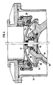
- the device shown in fig. 1 comprises a housing 10 provided with two opposite flanges 12, 14 to be connected in a flow pipe for bulk products, such as for example coal powder.
- the upper part of the housing 10 is designed in the form of tubing 16 intended to be closed or opened using a closing element 20.
- This closing element 20 comprises a spherical cap 22 mounted on a pivoting support 18 which is carried by two shafts 24, 26 which are housed and supported in opposite bearings of the housing 10 so as to allow the element closure 20 to pivot about its horizontal axis O between the closed position according to FIG. 1 and an opening position offset by 90 °.
- One of the shafts of the support eg the shaft 26 is subjected, outside the housing 10, to a drive mechanism for pivoting the closing element 20, while the other shaft 24 carries outside the housing 10 a weight 28 which is greater than the weight of the closure element 22 in order to ensure that the latter a stable position in the closed position when the drive means fail.
- the sealing element 20 is sealed in the closed position by an annular seal 30 housed in a support 32 fixed to the housing 10, the support 32 being designed to allow quick and easy disassembly of the seal 30.
- the latter is axially displaceable relative to its support 18.
- a cylindrical scraper 34 is preferably mounted axially inside the seal 30.
- This scraper 34 is supported by the housing 10, by elastic means, which are, in the example illustrated, a compensator 36 and which drives the scraper 34 elastically against the surface of the cap 22. This measure is intended to protect the seal 30 against crusts of material remaining attached to the cap 22 and which are detached by the scraper 34 during the movement of the cap 22.
- Figs. 2 and 3 schematically illustrate the mechanism for actuating the shutter 20.
- This mechanism comprises a jack 38, or other drive means, which is mounted between a console 40 secured to the housing 10 and an arm 42 fixed to the shaft 26.
- closing the shutter 20, i.e. the pivoting of the shutter 20 from the position of FIG. 3 towards the position of fig. 2 is produced by releasing the piston rod from the cylinder of the cylinder 38, the opening being carried out by the reverse operation.
- a helical spring 44 is provided inside the jack 38 and the action of this spring 44 contributes to the closing of the shutter 20 and opposes its opening.
- This spring 44 is provided in combination with or in replacement of the weight 28 of FIG. 1 and its power, possibly associated with that of the weight 28, is sufficient to close the shutter in the event of failure of the jack 38.
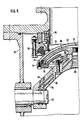
- Fig. 4 shows a first embodiment for lifting the spherical cap 22 and applying it sealingly against the seat 30, the left part of the figure representing the cap in the raised position, while the right part shows the cap in the lowered position.
- This cap 22 is carried by a piston 50 which is mounted axially, in a sliding manner, in the center of the support 18.
- This piston 50 is associated with a spring 52, eg a helical spring or a spring of the BELLEVILLE type, the action keeps the cap 22 in the position illustrated in the right part of the figure.
- the peripheral part of the cap 22 is connected tightly to the support 18 by means of a compensator 54 which allows axial displacement of the cap 22.
- the space defined between the cap 22 and the support 18 is constituted in the form of a pneumatic chamber 56 which is connected by a channel 58 through the support 18 to a source of pneumatic fluid.
- the pressurization of this chamber 56 lifts the cap 22 against the action of the spring 52 into the position illustrated on the left of FIG. 4.
- this movement is preferably limited by a shoulder 60 which forms a stop with the support 18.
- this space is preferably connected to the chamber 56 by a channel 62 in the support 18.
- Figs. 5 and 6 show a second embodiment for lifting the cap 22 from its support 18 and apply it tightly against the annular seal 30.
- a piston 66 with a spherical surface is fixed, in a removable manner, using a threaded sleeve 68 on the support 18.
- This spherical piston 66 extends below the spherical cap 22 and its outer edge is provided with a peripheral seal 70 which cooperates with the inner cylindrical surface of a peripheral skirt 72 forming part of the cap 22.
- L space formed between the cap 22 and the piston 66 constitutes a first chamber 74, the seal of which is ensured by the seal 70, which nevertheless allows axial displacement of the cap 22 relative to the piston 66 without the seal being disturbed.
- This chamber 74 is connected by a channel 76 through the shaft 24, the support 18 and the threaded sleeve 68 so that the pressurization of the chamber 74 using a pneumatic fluid, raises the cap 22 of its support 18 for applying it against the seal 30 as shown in FIG. 6.
- annular element 78 also with a spherical surface, is screwed onto the edge of the skirt 72 of the cap 22.
- This annular element 78 extends below the spherical piston 66 and its inner edge is connected by a cylindrical compensator 80 to the support 18, so as to define a second chamber 82 between the element 78 and the spherical piston 66, the sealing of this chamber being ensured by the seal 70 and the compensator 80.
- This second pneumatic chamber 82 is connected by a channel 84 also evolving through the support 18 and the shaft 24 to a source of pneumatic fluid. The pressurization of this chamber 82 exerts a vertical force on the annular element 78 tending to maintain the cap on the support 18, according to FIG.
- the first pneumatic chamber 74 is ventilated.
- the outer edges of the piston 66 form stops for limiting the movement of the cap 22, in cooperation either with the edge of the cap 22 when the chamber 82 is under pressure as shown in fig.5, or with the element ring 78 as shown in FIG. 6 when the chamber 74 is pressurized.
- the pressure prevailing inside the housing exerts on the movable part, i.e. the cap 22 and its lower extension by the annular element 78 a pressure whose maximum effect may correspond to a force exerted on an area of effective radius corresponding to the average radius of the compensator 80 since beyond this radius the forces on the annular element 78 and the corresponding parts of the cap 22 compensate each other.
- the forces resulting from the pneumatic pressures in the chambers 74 and 82 exert their effect on a substantially larger surface, so that the pressure of the pneumatic fluid must not be greater than the pressure prevailing in the housing 10.
Applications Claiming Priority (2)
| Application Number | Priority Date | Filing Date | Title |
|---|---|---|---|
| LU87482 | 1989-03-17 | ||
| LU87482A LU87482A1 (fr) | 1989-03-17 | 1989-03-17 | Dispositif d'obturation de conduites de transport de produits en vrac |
Publications (2)
| Publication Number | Publication Date |
|---|---|
| EP0387514A2 true EP0387514A2 (de) | 1990-09-19 |
| EP0387514A3 EP0387514A3 (de) | 1990-11-28 |
Family
ID=19731155
Family Applications (1)
| Application Number | Title | Priority Date | Filing Date |
|---|---|---|---|
| EP19900101866 Withdrawn EP0387514A3 (de) | 1989-03-17 | 1990-01-31 | Absperrvorrichtung für Schüttgut-Transportleitungen |
Country Status (6)
| Country | Link |
|---|---|
| US (1) | US5076737A (de) |
| EP (1) | EP0387514A3 (de) |
| CA (1) | CA2011336A1 (de) |
| DE (1) | DE4003466A1 (de) |
| GB (1) | GB2230325B (de) |
| LU (1) | LU87482A1 (de) |
Families Citing this family (17)
| Publication number | Priority date | Publication date | Assignee | Title |
|---|---|---|---|---|
| DE4410087C2 (de) * | 1994-03-24 | 1997-08-07 | Mann & Hummel Filter | Verschluß für ein im Unterdruck arbeitendes Fördergerät |
| DE4436202A1 (de) * | 1994-09-29 | 1996-04-11 | Rautenkranz Int Hermann | Kellyhahn mit doppelt gelagertem Kugelküken |
| US7484710B2 (en) * | 2002-03-19 | 2009-02-03 | Fisher Controls International Llc | Fluid flow control valve with high temperature bi-directional shutoff |
| WO2012057081A1 (ja) * | 2010-10-29 | 2012-05-03 | 株式会社アルバック | 凍結真空乾燥装置及び凍結粒子製造方法 |
| CN102384275B (zh) * | 2011-06-24 | 2012-12-26 | 中冶赛迪工程技术股份有限公司 | 密封阀 |
| EP2732186B1 (de) * | 2011-07-11 | 2017-11-01 | Fisher Controls International Llc | Balggetriebene dichtungsanordnung für ein drehstellventil |
| US9248995B2 (en) * | 2013-02-27 | 2016-02-02 | Carlos M. Ascua | Vacuum valve |
| CN105351542B (zh) * | 2015-11-11 | 2017-10-27 | 合肥通用环境控制技术有限责任公司 | 一种煤粉流量调节阀的阀芯结构 |
| CN105423759B (zh) * | 2015-11-24 | 2017-10-13 | 中冶南方工程技术有限公司 | 一种还原炉底部卸料装置及其卸料方法 |
| CN105650298B (zh) * | 2016-04-13 | 2018-02-09 | 江苏艮德电力设备有限公司 | 一种圆顶阀 |
| US10106375B1 (en) * | 2017-08-10 | 2018-10-23 | Carlos M. Ascua | Split vacuum elevator system |
| CN108825859B (zh) * | 2018-08-29 | 2023-07-18 | 江苏保丽洁环境科技股份有限公司 | 废气处理设备中吸附箱的废气出口机构 |
| CA3159547A1 (en) | 2019-11-21 | 2021-05-27 | Itt Manufacturing Enterprises Llc | Dual motion shutoff valve |
| US11946557B2 (en) * | 2020-02-14 | 2024-04-02 | Crane Chempharma & Energy Corp. | Valve with unobstructed flow path having increased flow coefficient |
| US11953113B2 (en) | 2020-02-14 | 2024-04-09 | Crane Chempharma & Energy Corp. | Valve with unobstructed flow path having increased flow coefficient |
| US11841089B2 (en) | 2020-02-14 | 2023-12-12 | Crane Chempharma & Energy Corp. | Valve with unobstructed flow path having increased flow coefficient |
| US11519509B2 (en) | 2020-02-14 | 2022-12-06 | Crane Chempharma & Energy Corp. | Valve with unobstructed flow path having increased flow coefficient |
Citations (3)
| Publication number | Priority date | Publication date | Assignee | Title |
|---|---|---|---|---|
| US2910266A (en) * | 1959-10-27 | Poppet-butterfly valve | ||
| BE685899A (de) * | 1965-08-25 | 1967-02-01 | ||
| EP0346216A1 (de) * | 1988-06-07 | 1989-12-13 | Etablissements NEU Société Anonyme dite: | Kugelventil |
Family Cites Families (9)
| Publication number | Priority date | Publication date | Assignee | Title |
|---|---|---|---|---|
| FR346216A (fr) * | 1904-09-14 | 1905-01-07 | Hugh Mowlem | Dispositif pour ouvrir les enveloppes |
| GB213540A (en) * | 1923-03-28 | 1924-06-26 | Albert Huguenin | Improvements in rotary valves for pipe lines |
| US2598207A (en) * | 1946-06-14 | 1952-05-27 | Bailey Meter Co | Valving apparatus |
| FR1559238A (de) * | 1968-03-05 | 1969-03-07 | ||
| US3599832A (en) * | 1969-12-23 | 1971-08-17 | Ind Pneumatic Systems Inc | Flow control of fluidized material |
| GB1542518A (en) * | 1976-07-06 | 1979-03-21 | Euratom | Vacuum shut-off valves |
| SU1416403A1 (ru) * | 1987-01-23 | 1988-08-15 | Горловский филиал Донецкого политехнического института | Устройство дл загрузки сыпучего материала в пневмотранспортную установку |
| DE8705189U1 (de) * | 1987-04-07 | 1987-06-04 | Bergwerksverband Gmbh, 4300 Essen, De | |
| US4872785A (en) * | 1988-01-22 | 1989-10-10 | Schrage Timothy L | Shut-off means for air-actuated planter |
-
1989
- 1989-03-17 LU LU87482A patent/LU87482A1/fr unknown
-
1990
- 1990-01-31 EP EP19900101866 patent/EP0387514A3/de not_active Withdrawn
- 1990-02-06 DE DE4003466A patent/DE4003466A1/de not_active Withdrawn
- 1990-02-09 GB GB9002912A patent/GB2230325B/en not_active Expired - Fee Related
- 1990-02-27 US US07/486,614 patent/US5076737A/en not_active Expired - Fee Related
- 1990-03-02 CA CA002011336A patent/CA2011336A1/en not_active Abandoned
Patent Citations (3)
| Publication number | Priority date | Publication date | Assignee | Title |
|---|---|---|---|---|
| US2910266A (en) * | 1959-10-27 | Poppet-butterfly valve | ||
| BE685899A (de) * | 1965-08-25 | 1967-02-01 | ||
| EP0346216A1 (de) * | 1988-06-07 | 1989-12-13 | Etablissements NEU Société Anonyme dite: | Kugelventil |
Also Published As
| Publication number | Publication date |
|---|---|
| EP0387514A3 (de) | 1990-11-28 |
| US5076737A (en) | 1991-12-31 |
| GB2230325B (en) | 1993-07-28 |
| GB9002912D0 (en) | 1990-04-04 |
| DE4003466A1 (de) | 1990-09-20 |
| GB2230325A (en) | 1990-10-17 |
| LU87482A1 (fr) | 1990-10-02 |
| CA2011336A1 (en) | 1990-09-17 |
Similar Documents
| Publication | Publication Date | Title |
|---|---|---|
| EP0387514A2 (de) | Absperrvorrichtung für Schüttgut-Transportleitungen | |
| EP0386460A2 (de) | Absperrvorrichtung für Schüttguttransportleitungen | |
| EP0187729B1 (de) | Kugelhahn | |
| FR2588055A1 (fr) | Vanne a passage direct | |
| EP0246584B1 (de) | Ventil mit Membran | |
| EP0952376B1 (de) | Doppelsitzventil mit aufblasbarer Membran | |
| FR2783791A1 (fr) | Mecanisme de direction a insert en mousse | |
| FR2516195A1 (fr) | Obturateur pour robinet melangeur commande par levier unique | |
| FR2755736A1 (fr) | Dispositif de debrayage hydraulique a piston annulaire muni d'un joint | |
| EP0190528A1 (de) | Pneumatische oder hydraulische Stelleinrichtung | |
| EP0172053B1 (de) | Selbstreinigende Ventile für pulverige, körnige und teigartige Produkte | |
| EP1193062B1 (de) | Dichtungsanordnung für eine Kammerrakel. | |
| FR2619884A1 (fr) | Soupape de securite pilotee | |
| FR2619430A1 (fr) | Dispositif d'accouplement et de freinage pouvant etre commute par un fluide compressible, notamment pneumatique | |
| FR2482878A1 (de) | ||
| EP0569262B1 (de) | Volumetrische Pumpe | |
| FR2759139A1 (fr) | Vanne a coulisseau | |
| EP3770472A1 (de) | Perfektioniertes drosselventil für den transport von fluiden unter hohem oder extremem druck | |
| FR2658872A1 (fr) | Perfectionnements apportes aux verins pour fluide sous pression. | |
| FR2562201A1 (fr) | Dispositif d'etancheite pour joints mo biles de tuyauteries de fluides | |
| FR2961566A1 (fr) | Actionneur a verin d'un organe mobile dans une turbomachine | |
| FR2584162A1 (fr) | Clapet anti-retour a opercules multiples, destine notamment aux installations de refoulement | |
| FR2570145A1 (fr) | Mecanisme de roulement a garniture d'etancheite a anneaux de glissement | |
| FR2570469A1 (fr) | Dispositif pour le remplissage des bouteilles de gaz butane et propane | |
| FR2601081A1 (fr) | Dispositif de pompage pour prelever un produit visqueux epais dans un fut |
Legal Events
| Date | Code | Title | Description |
|---|---|---|---|
| PUAI | Public reference made under article 153(3) epc to a published international application that has entered the european phase |
Free format text: ORIGINAL CODE: 0009012 |
|
| AK | Designated contracting states |
Kind code of ref document: A2 Designated state(s): BE ES FR IT NL |
|
| PUAL | Search report despatched |
Free format text: ORIGINAL CODE: 0009013 |
|
| AK | Designated contracting states |
Kind code of ref document: A3 Designated state(s): BE ES FR IT NL |
|
| 17P | Request for examination filed |
Effective date: 19910415 |
|
| 17Q | First examination report despatched |
Effective date: 19930302 |
|
| STAA | Information on the status of an ep patent application or granted ep patent |
Free format text: STATUS: THE APPLICATION HAS BEEN WITHDRAWN |
|
| 18W | Application withdrawn |
Withdrawal date: 19930413 |