EP0387367B1 - Untersetzungsgetriebe - Google Patents
Untersetzungsgetriebe Download PDFInfo
- Publication number
- EP0387367B1 EP0387367B1 EP89104463A EP89104463A EP0387367B1 EP 0387367 B1 EP0387367 B1 EP 0387367B1 EP 89104463 A EP89104463 A EP 89104463A EP 89104463 A EP89104463 A EP 89104463A EP 0387367 B1 EP0387367 B1 EP 0387367B1
- Authority
- EP
- European Patent Office
- Prior art keywords
- shaft
- casing
- shafts
- flange
- reducer
- Prior art date
- Legal status (The legal status is an assumption and is not a legal conclusion. Google has not performed a legal analysis and makes no representation as to the accuracy of the status listed.)
- Expired - Lifetime
Links
- 239000003638 chemical reducing agent Substances 0.000 title claims description 44
- 230000009467 reduction Effects 0.000 claims description 14
- 238000004873 anchoring Methods 0.000 claims description 9
- 230000002093 peripheral effect Effects 0.000 claims description 2
- 230000005540 biological transmission Effects 0.000 abstract description 5
- 230000000284 resting effect Effects 0.000 abstract 2
- 230000008878 coupling Effects 0.000 description 7
- 238000010168 coupling process Methods 0.000 description 7
- 238000005859 coupling reaction Methods 0.000 description 7
- 241000282472 Canis lupus familiaris Species 0.000 description 6
- 238000010276 construction Methods 0.000 description 3
- 238000010586 diagram Methods 0.000 description 3
- 230000000694 effects Effects 0.000 description 3
- 238000010348 incorporation Methods 0.000 description 1
- 239000010687 lubricating oil Substances 0.000 description 1
- 238000004519 manufacturing process Methods 0.000 description 1
- 230000007246 mechanism Effects 0.000 description 1
- 238000010926 purge Methods 0.000 description 1
Images


Classifications
-
- F—MECHANICAL ENGINEERING; LIGHTING; HEATING; WEAPONS; BLASTING
- F16—ENGINEERING ELEMENTS AND UNITS; GENERAL MEASURES FOR PRODUCING AND MAINTAINING EFFECTIVE FUNCTIONING OF MACHINES OR INSTALLATIONS; THERMAL INSULATION IN GENERAL
- F16H—GEARING
- F16H57/00—General details of gearing
- F16H57/02—Gearboxes; Mounting gearing therein
- F16H57/033—Series gearboxes, e.g. gearboxes based on the same design being available in different sizes or gearboxes using a combination of several standardised units
-
- F—MECHANICAL ENGINEERING; LIGHTING; HEATING; WEAPONS; BLASTING
- F16—ENGINEERING ELEMENTS AND UNITS; GENERAL MEASURES FOR PRODUCING AND MAINTAINING EFFECTIVE FUNCTIONING OF MACHINES OR INSTALLATIONS; THERMAL INSULATION IN GENERAL
- F16H—GEARING
- F16H1/00—Toothed gearings for conveying rotary motion
- F16H1/02—Toothed gearings for conveying rotary motion without gears having orbital motion
- F16H1/20—Toothed gearings for conveying rotary motion without gears having orbital motion involving more than two intermeshing members
-
- Y—GENERAL TAGGING OF NEW TECHNOLOGICAL DEVELOPMENTS; GENERAL TAGGING OF CROSS-SECTIONAL TECHNOLOGIES SPANNING OVER SEVERAL SECTIONS OF THE IPC; TECHNICAL SUBJECTS COVERED BY FORMER USPC CROSS-REFERENCE ART COLLECTIONS [XRACs] AND DIGESTS
- Y10—TECHNICAL SUBJECTS COVERED BY FORMER USPC
- Y10T—TECHNICAL SUBJECTS COVERED BY FORMER US CLASSIFICATION
- Y10T74/00—Machine element or mechanism
- Y10T74/21—Elements
- Y10T74/2186—Gear casings
Definitions
- the object of the invention refers to a speed reducer, whose features permit transmission for operation of all types of mechanisms which require a slow operating speed and replaces all conventional elements, with the advantage of taking up very little space and the obtainment of better efficiency.
- a speed reducer has the task of transmission thanks to which the tree or main shaft of a machine, can rotate with a speed lower than the one of the motor tree which moves it.
- the lateral stresses to which the shafts of the gearing are subjected determines the production of play and deformations which are the ones which wear the shafts and gearing producing vibrations and breakage.
- the invention proposes the speed reducer which is described, which has the advantages of being a compact unit, with cylindric gearing and coaxial and parallel shafts, occupying very little space with a higher efficiency.
- the reducer comprises a monoblock casing which inside has a special distribution, by which it is obtained that none of the gearings, pinions as well as wheels, are overhanging. For this reason, all its shafts are located between two supports with bearings with a more balanced construction and greater resistance of the reducer unit.
- the casing is obtained in a single block, which comprises a front mouth dimensioned to this effect, so that through it the different component parts can be assembled, among which stands out a fastening flange with a disk shape provided with a center boring for the shafts of two coaxial gearing and peripheral borings for the anchoring thereof in a seat foreseen inside the casing.
- This flange has a gap through which the bottom gearing of the reducer can be assembled.
- the reducer unit is conceived for great versatility by means of coupling the corresponding covers in the entrance of the shaft of the power supply of the motor as well as in the reducer outlet.
- the reducer offers various possibilities:
- This arrangement of elements makes it possible to have the shaft of power supply and the outlet shaft in axial prolongation, while the third shaft remains parallel to these two and the fourth one is mounted with the addition of a replacement cover.
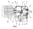
- a motor reducer with two stages seen in vertical section is seen in figure 1.
- the casing -1- corresponds to a reducer with dogs -2- for support on the floor.
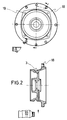
- Figure 2 It represents the cover in a front and sectional view. All around it there is a wing -18- with equidistant borings for clamping thereof to the casing. On the other side there are also flanges for connection to the motor.
- Figure 3 It represents the section of a cover -20-which like -3- represented in figure 2, has its wing with equidistant borings for clamping thereof to the casing.
- the front connection end to the motor has been deleted, as the reducer has to be incorporated at the midpoint between a drive shaft and another driven shaft.
- This cover is for a two stage reduction reducer.
- Figure 4 It represents a front raised and sectional view of the plate or flange -4-. In the front view one can see the gap -6- which permits the assembly of the bottom shaft.
- Figure 5 It shows a front raised and sectional view of the bridge -25- for support of the bottom shaft of the three stage reducer (See figure 6.)
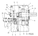
- Figue 6. It represents a diagram of a three stage reduction motor reducer, with dogs.
- the only variation with regard to figure 1 is the cover -21- (figure 9) which permits the arrangement of a fourth parallel shaft -22-, with pinion -23-, through which it is meshed with the wheel -24- mounted on the shaft -12-(figure 1.)
- the nose of coupling to the motor maintains the same features as in the case of the cover of figure 2, and likewise the flange -18- for anchoring to the casing -1-. In this case the nose remains excentric to the flange -18- to permit the arrangement of the cited fourth shaft -22-, with another internal support -25.-
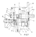
- FIG. 7 This figure represents the diagram of a three stage reduction motor reducer, whose features are idnetical to the one represented in figure 6, except in the exterior flange -26- of the casing, in the surface opposite the motor position, in other words, of the driven shaft outlet -13- for anchoring the reducer to the wall.
- Figure 8 It shows the casing just as it corresponds to the one of figure 7, where one can clearly see all the internal protusions (figure 1) and the access mouth -2- to the inside which permits assembly of the different elements and the location of the different covers depending on the type of reducer. As can be seen it is obtained in a single piece.
- the housings -10-11-and -14- for the bearings of the shafts and the protusion -5- for the cover-flange for support of the coaxial shafts are visible therein.
- the hole -27- for purging the lubricating oil can also be seen in this figure.
- Figure 9. It corresponds to different views and sections in physical representation of the cover of a motor reducer with three stages of reduction to which the motor is coupled, as shown in the diagrams of figures 6 and 7.
- the support -25- (figure 5) is coupled to the rear end -28.-
- Figure 10. It corresponds to different views and sections, in physical representation of the cover of the three stage reducer, through which the shaft primary receiver of the power supply in which the nose of coupling to the motor has been suppressed.
- This cover is mounted on the three stage reducers which have to be incorporated at the midpoint between the drive shaft and other driven shaft. In the inside part it has the end -28- like the cover of figure 9.
Landscapes
- Engineering & Computer Science (AREA)
- General Engineering & Computer Science (AREA)
- Mechanical Engineering (AREA)
- General Details Of Gearings (AREA)
- Gear Transmission (AREA)
- Pharmaceuticals Containing Other Organic And Inorganic Compounds (AREA)
Claims (4)
- Reduktionsgetriebe, das ein Gehäuse (1) umfaßt, das in einem Stück gegossen ist, sowie eine Reihe von Wellen (7, 12, 13, 22), die Reduktionszahnräder (4, 9, 17, 24) und Ritzel (8, 23) tragen, und das eine Öffnung (2) an seiner Vorderseite hat, wobei durch diese Öffnung (2, 21) das Innere des Gehäuses (1) zugänglich ist, und wobei dieses Gehäuse durch einen abnehmbaren Deckel (3) verschlossen ist, wobei eine Antriebswelle (12, 22) in dem Deckel (3) gelagert ist, während eine Abtriebswelle (13) an der gegenüberliegenden Seite im Gehäuse (1) gelagert ist, eine Reihe von Vorsprüngen (5) zur Befestigung von Hilfsträgerflanschen (4) der Wellen (12, 13), Lager (10, 14, 15) zum Tragen der Wellen (7, 12, 13, 22), wobei der Deckel (2, 21) eine Welle (12) oder zwei Wellen (12, 22) des Reduktionssystems in Abhängigkeit davon trägt, ob es ein zwei- oder dreistufiges Reduktionsgetriebe ist, wobei der Flansch (4) plattenförmig ist und Umfangsbohrungen zur Befestigung mittels Schrauben an einer Auflage (5) hat, die in das Innere des Gehäuses (1) vorsteht, wobei der Flansch (4) des weiteren eine Mittelbohrung zum gleichzeitigen Tragen der Enden der beiden Wellen (12, 13) hat, die sich in axialer Verlängerung befinden, wobei eine der Wellen die Abtriebswelle (13) und die andere Welle (12) eine angetriebene Welle ist, und eine Zwischenwelle (7) mit einem Ritzel (8) und einem Zahnrad (9) parallel zu der Abtriebswelle (13) ist,
dadurch gekennzeichnet, daß
der Flansch (4) einen Spalt hat, der den Durchgang der Zwischenwelle (7) ermöglicht, wobei die Zwischenwelle an ihrem Ende gegenüber der Rückwand des Gehäuses (1) in einer Lagerung im vorderen Abschnitt des Gehäuses (1) in axialer Verlängerung der Zwischenwelle (7) gelagert ist. - Reduktionsgetriebe nach Anspruch 1, dadurch gekennzeichnet, daß die Kraftzufuhr des Motors direkt über die Antriebswelle oder über eine vierte Welle (22) parallel zu den vorherigen erfolgt, die in ein zusätzliches Rad (24) eingreift, das auf der ursprünglichen Antriebswelle angebracht ist, wobei diese an einem Hilfsdeckel (21) gelagert bleibt, an dem außerdem die neue Welle angebracht wird, die zu einer Antriebswelle wird, da sie direkt die Kraft vom Motor empfängt.
- Reduktionsgetriebe nach Anspruch 1 und 2, dadurch gekennzeichnet, daß in der vorderen Rückwand des Gehäuses (1) die Anordnung eines Flansches (26) im hinteren Teil des Gehäuses zur Befestigung des Reduktionsgetriebes an der Wand vorgesehen ist, der aus einem Außenflansch mit Bohrungen zur Durchführung von Schrauben besteht.
- Reduktionsgetriebe nach Anspruch 1 und 2, dadurch gekennzeichnet, daß die Welle (22) in einer Lagerung (25) an der Innenseite des Deckels (3) in einem Abstand gelagert ist, der ausreicht, um das Zusammenwirken des Ritzels (23) der Welle (22) mit dem Zahnrad (24) der Welle (12) zu ermöglichen.
Priority Applications (1)
| Application Number | Priority Date | Filing Date | Title |
|---|---|---|---|
| AT89104463T ATE95286T1 (de) | 1989-03-06 | 1989-03-14 | Untersetzungsgetriebe. |
Applications Claiming Priority (2)
| Application Number | Priority Date | Filing Date | Title |
|---|---|---|---|
| ES8900801 | 1989-03-06 | ||
| ES8900801A ES2012680A6 (es) | 1989-03-06 | 1989-03-06 | Reductor de velocidad. |
Publications (2)
| Publication Number | Publication Date |
|---|---|
| EP0387367A1 EP0387367A1 (de) | 1990-09-19 |
| EP0387367B1 true EP0387367B1 (de) | 1993-09-29 |
Family
ID=8260779
Family Applications (1)
| Application Number | Title | Priority Date | Filing Date |
|---|---|---|---|
| EP89104463A Expired - Lifetime EP0387367B1 (de) | 1989-03-06 | 1989-03-14 | Untersetzungsgetriebe |
Country Status (7)
| Country | Link |
|---|---|
| US (1) | US5058456A (de) |
| EP (1) | EP0387367B1 (de) |
| AT (1) | ATE95286T1 (de) |
| CA (1) | CA1311144C (de) |
| DE (1) | DE68909585T2 (de) |
| ES (1) | ES2012680A6 (de) |
| PT (1) | PT90010B (de) |
Cited By (1)
| Publication number | Priority date | Publication date | Assignee | Title |
|---|---|---|---|---|
| US7063170B2 (en) | 2003-02-26 | 2006-06-20 | Black & Decker Inc. | Flexible power tool motor pack and method of making the same |
Families Citing this family (24)
| Publication number | Priority date | Publication date | Assignee | Title |
|---|---|---|---|---|
| CH684358A5 (de) * | 1990-07-07 | 1994-08-31 | Stoeber Antriebstech Gmbh & Co | Getriebegehäuse, insbesondere für Stirnrad/Schneckengetriebe oder Schneckengetriebe. |
| AT413054B (de) * | 1992-05-04 | 2005-10-15 | Joerg Helmut | Getriebegehäuse |
| US5404772A (en) * | 1992-11-06 | 1995-04-11 | Dana Corporation | Transmission housing |
| US5284067A (en) * | 1992-12-15 | 1994-02-08 | Borg-Warner Automotive, Inc. | Manual transmission shaft center control support device |
| DE4329495A1 (de) * | 1993-09-01 | 1995-03-02 | Rostock Dieselmotoren | Koaxialgetriebe mit 3 Nebenwellen |
| DE4420305C1 (de) * | 1994-06-10 | 1995-05-24 | Carl Bockwoldt Gmbh & Co Kg Ge | Getriebe für einen Getriebemotor |
| DE9413344U1 (de) * | 1994-08-18 | 1995-12-14 | Getriebebau-Nord Schlicht + Küchenmeister GmbH & Co, 22941 Bargteheide | Getriebe |
| IT1285600B1 (it) * | 1996-03-08 | 1998-06-18 | Bonfiglioli Riduttori Spa | Riduttore angolare a piu' stadi |
| IT1285601B1 (it) * | 1996-03-08 | 1998-06-18 | Bonfiglioli Riduttori Spa | Riduttore angolare a piu' stadi |
| US5911793A (en) * | 1997-05-22 | 1999-06-15 | Kaye; Kenneth B. | Transmission with semi-floating shafts |
| DE19733546C1 (de) * | 1997-08-02 | 1999-04-22 | Lenze Gmbh & Co Kg Aerzen | Getriebebaukasten |
| USD424988S (en) * | 1998-03-02 | 2000-05-16 | Roy Rothlisberger | Differential cover |
| IT1306265B1 (it) * | 1998-07-21 | 2001-06-04 | Varvel Spa | Dispositivo variatore di velocita' |
| US7339298B2 (en) * | 2004-03-09 | 2008-03-04 | Superior Electric Holding Group Llc. | Compliant motor driven variable electrical device |
| US7665560B2 (en) * | 2007-02-22 | 2010-02-23 | Ford Global Technologies, Llc | Drivetrain for hybrid electric vehicle |
| DE102007025755A1 (de) * | 2007-06-01 | 2008-12-04 | Karl Hehl | Getriebeeinheit für eine Spritzgießeinheit |
| CN101808842B (zh) | 2007-09-27 | 2013-10-23 | 美国轮轴制造公司 | 机车轴组件 |
| USD600167S1 (en) * | 2007-09-27 | 2009-09-15 | American Axle & Manufacturing, Inc. | Carrier housing |
| WO2010149071A1 (zh) * | 2009-06-26 | 2010-12-29 | 金波 | 一种差动杠杆式减速器 |
| DE102009033259B4 (de) | 2009-07-14 | 2025-03-27 | Sew-Eurodrive Gmbh & Co Kg | Getriebemotorbausatz und Herstellverfahren für einen Getriebemotor |
| DE102015215733A1 (de) * | 2015-08-18 | 2017-02-23 | Mahle International Gmbh | Steller zum Verstellen eines Stellorgans |
| DE102015215732A1 (de) * | 2015-08-18 | 2017-02-23 | Mahle International Gmbh | Steller zum Verstellen eines Stellorgans |
| FR3133223B1 (fr) * | 2022-03-01 | 2024-03-15 | Serge Jallerat | Bielle active et améliorations des performances de la transformation du mouvement alternatif en mouvement rotatif ou inversement |
| CN120288616A (zh) * | 2025-06-12 | 2025-07-11 | 浙江西子富沃德电机有限公司 | 曳引机及其装配方法 |
Family Cites Families (15)
| Publication number | Priority date | Publication date | Assignee | Title |
|---|---|---|---|---|
| US2734393A (en) * | 1956-02-14 | ujenberger | ||
| US2503027A (en) * | 1947-05-31 | 1950-04-04 | Joseph D Christian | Gear reduction unit |
| DE818716C (de) * | 1948-12-24 | 1951-10-29 | Rhein Getriebe G M B H | Gehaeuse fuer Schneckengetriebe |
| DE1032635B (de) * | 1953-09-30 | 1958-06-19 | Tacke Maschinenfabrik Komm Ges | Zahnradgetriebe, insbesondere fuer den Zusammenbau mit Elektromotoren |
| US2835138A (en) * | 1955-10-19 | 1958-05-20 | Link Belt Co | Speed reducer gear drives |
| US2952165A (en) * | 1957-11-05 | 1960-09-13 | Falk Corp | Speed reducer |
| US2956451A (en) * | 1959-02-17 | 1960-10-18 | Bowman Spencer | Planetary gear-type speed reducer |
| US3154963A (en) * | 1962-07-16 | 1964-11-03 | Bowmar Instrument Corp | Miniature gear mechanism |
| US3222954A (en) * | 1963-08-09 | 1965-12-14 | Murray Co Texas Inc | Planetary speed-reducer |
| ES340906A1 (es) * | 1967-04-05 | 1968-09-16 | Asea Ab | Un motor con engranajes reductores. |
| US4020715A (en) * | 1975-03-27 | 1977-05-03 | Steel Belt, Inc. | Speed reducer and housing therefor |
| IT1119624B (it) * | 1979-12-18 | 1986-03-10 | Fiat Allis Macch Movi | Cambio di velocita del tipo con comando idraulico per l'innesto delle marce e contralbero |
| US4344501A (en) * | 1980-08-18 | 1982-08-17 | Gearco Limited | Geared hub |
| US4594911A (en) * | 1984-09-11 | 1986-06-17 | Getriebelbau-Nord Schlicht & Kuchenmeiser Gmbh & Co | Gear housing |
| DE3617379C1 (de) * | 1986-05-23 | 1987-07-02 | Berstorff Gmbh Masch Hermann | Rueckdrucklagerung fuer Doppelschneckenextruder |
-
1989
- 1989-03-06 ES ES8900801A patent/ES2012680A6/es not_active Expired - Lifetime
- 1989-03-14 AT AT89104463T patent/ATE95286T1/de not_active IP Right Cessation
- 1989-03-14 DE DE89104463T patent/DE68909585T2/de not_active Expired - Fee Related
- 1989-03-14 EP EP89104463A patent/EP0387367B1/de not_active Expired - Lifetime
- 1989-03-15 PT PT90010A patent/PT90010B/pt not_active IP Right Cessation
- 1989-03-15 CA CA000593559A patent/CA1311144C/en not_active Expired - Lifetime
-
1990
- 1990-11-16 US US07/616,830 patent/US5058456A/en not_active Expired - Fee Related
Cited By (2)
| Publication number | Priority date | Publication date | Assignee | Title |
|---|---|---|---|---|
| US7063170B2 (en) | 2003-02-26 | 2006-06-20 | Black & Decker Inc. | Flexible power tool motor pack and method of making the same |
| US7100705B2 (en) | 2003-02-26 | 2006-09-05 | Black & Decker Inc. | Flexible power tool motor pack and method of making the same |
Also Published As
| Publication number | Publication date |
|---|---|
| CA1311144C (en) | 1992-12-08 |
| EP0387367A1 (de) | 1990-09-19 |
| ES2012680A6 (es) | 1990-04-01 |
| PT90010B (pt) | 1995-06-30 |
| PT90010A (pt) | 1990-11-07 |
| ATE95286T1 (de) | 1993-10-15 |
| DE68909585D1 (de) | 1993-11-04 |
| DE68909585T2 (de) | 1994-04-28 |
| US5058456A (en) | 1991-10-22 |
Similar Documents
| Publication | Publication Date | Title |
|---|---|---|
| EP0387367B1 (de) | Untersetzungsgetriebe | |
| US4528867A (en) | Transmission case for tractors | |
| WO2003066359A2 (en) | Axle assembly | |
| US2636390A (en) | Power take-off | |
| US6524203B2 (en) | Power transmission device of engine | |
| US4191073A (en) | Drive assembly having an improved sun gear mounting | |
| ES2010832A6 (es) | Disposicion de bomba en una transmision. | |
| CN209164493U (zh) | 齿轮减速装置及安装齿轮减速装置的垃圾桶 | |
| CN217736198U (zh) | 电动窗帘变速箱 | |
| WO1999041099A2 (en) | Power take-off unit having integral pump mounting flange | |
| EP0974774B1 (de) | Untersetzungsgetriebe | |
| JPH09329201A (ja) | 多段式斜交継ぎ手 | |
| CN218335625U (zh) | 一种带有多级减速齿轮的直流减速电机 | |
| CN2246215Y (zh) | 一种合成减速驱动装置 | |
| CN210686867U (zh) | 一种单输入回转盘式行星减速箱结构 | |
| US4515038A (en) | Power transmission mechanism for motorcycles | |
| CN2747415Y (zh) | 法兰盘式无级调速垂直输出减速机 | |
| CN220405498U (zh) | 一种混合传动的双轴拌馅机 | |
| CN221779841U (zh) | 一种转舵机构 | |
| CN222811184U (zh) | 一种用于网格结构铺放机的双轴驱动装置 | |
| CN1085613C (zh) | 用于输送人的机械装置中的变速箱 | |
| CN222798068U (zh) | 一种少齿差减速器 | |
| CN109654201B (zh) | 一种施工升降机用减速箱及其安装方法 | |
| CN212079026U (zh) | 小型电动金库门 | |
| CN219251622U (zh) | 一种麻将机上牌机构及其驱动组件 |
Legal Events
| Date | Code | Title | Description |
|---|---|---|---|
| PUAI | Public reference made under article 153(3) epc to a published international application that has entered the european phase |
Free format text: ORIGINAL CODE: 0009012 |
|
| AK | Designated contracting states |
Kind code of ref document: A1 Designated state(s): AT BE CH DE FR GB GR IT LI LU NL SE |
|
| 17P | Request for examination filed |
Effective date: 19901220 |
|
| 17Q | First examination report despatched |
Effective date: 19920602 |
|
| GRAA | (expected) grant |
Free format text: ORIGINAL CODE: 0009210 |
|
| AK | Designated contracting states |
Kind code of ref document: B1 Designated state(s): AT BE CH DE FR GB GR IT LI LU NL SE |
|
| PG25 | Lapsed in a contracting state [announced via postgrant information from national office to epo] |
Ref country code: LI Effective date: 19930929 Ref country code: CH Effective date: 19930929 |
|
| REF | Corresponds to: |
Ref document number: 95286 Country of ref document: AT Date of ref document: 19931015 Kind code of ref document: T |
|
| REF | Corresponds to: |
Ref document number: 68909585 Country of ref document: DE Date of ref document: 19931104 |
|
| ITF | It: translation for a ep patent filed | ||
| REG | Reference to a national code |
Ref country code: CH Ref legal event code: PL |
|
| ET | Fr: translation filed | ||
| REG | Reference to a national code |
Ref country code: GR Ref legal event code: FG4A Free format text: 3010241 |
|
| EPTA | Lu: last paid annual fee | ||
| PLBE | No opposition filed within time limit |
Free format text: ORIGINAL CODE: 0009261 |
|
| STAA | Information on the status of an ep patent application or granted ep patent |
Free format text: STATUS: NO OPPOSITION FILED WITHIN TIME LIMIT |
|
| 26N | No opposition filed | ||
| EAL | Se: european patent in force in sweden |
Ref document number: 89104463.8 |
|
| REG | Reference to a national code |
Ref country code: GB Ref legal event code: 732E |
|
| NLS | Nl: assignments of ep-patents |
Owner name: FELLAR, S.A. TE PATERNA, SPANJE. |
|
| ITPR | It: changes in ownership of a european patent |
Owner name: CESSIONE;FELLAR S.A. |
|
| PGFP | Annual fee paid to national office [announced via postgrant information from national office to epo] |
Ref country code: GR Payment date: 19960228 Year of fee payment: 8 |
|
| PGFP | Annual fee paid to national office [announced via postgrant information from national office to epo] |
Ref country code: SE Payment date: 19960229 Year of fee payment: 8 |
|
| PGFP | Annual fee paid to national office [announced via postgrant information from national office to epo] |
Ref country code: LU Payment date: 19960301 Year of fee payment: 8 Ref country code: FR Payment date: 19960301 Year of fee payment: 8 |
|
| PGFP | Annual fee paid to national office [announced via postgrant information from national office to epo] |
Ref country code: GB Payment date: 19960305 Year of fee payment: 8 |
|
| PGFP | Annual fee paid to national office [announced via postgrant information from national office to epo] |
Ref country code: BE Payment date: 19960312 Year of fee payment: 8 |
|
| PGFP | Annual fee paid to national office [announced via postgrant information from national office to epo] |
Ref country code: AT Payment date: 19960327 Year of fee payment: 8 |
|
| PGFP | Annual fee paid to national office [announced via postgrant information from national office to epo] |
Ref country code: NL Payment date: 19960331 Year of fee payment: 8 |
|
| PGFP | Annual fee paid to national office [announced via postgrant information from national office to epo] |
Ref country code: DE Payment date: 19960430 Year of fee payment: 8 |
|
| REG | Reference to a national code |
Ref country code: FR Ref legal event code: TP |
|
| PG25 | Lapsed in a contracting state [announced via postgrant information from national office to epo] |
Ref country code: LU Free format text: LAPSE BECAUSE OF NON-PAYMENT OF DUE FEES Effective date: 19970314 Ref country code: GB Effective date: 19970314 Ref country code: AT Effective date: 19970314 |
|
| PG25 | Lapsed in a contracting state [announced via postgrant information from national office to epo] |
Ref country code: SE Effective date: 19970315 |
|
| PG25 | Lapsed in a contracting state [announced via postgrant information from national office to epo] |
Ref country code: BE Effective date: 19970331 |
|
| BERE | Be: lapsed |
Owner name: S.A FELLAR Effective date: 19970331 |
|
| PG25 | Lapsed in a contracting state [announced via postgrant information from national office to epo] |
Ref country code: GR Free format text: THE PATENT HAS BEEN ANNULLED BY A DECISION OF A NATIONAL AUTHORITY Effective date: 19970930 |
|
| PG25 | Lapsed in a contracting state [announced via postgrant information from national office to epo] |
Ref country code: NL Effective date: 19971001 |
|
| REG | Reference to a national code |
Ref country code: GR Ref legal event code: MM2A Free format text: 3010241 |
|
| GBPC | Gb: european patent ceased through non-payment of renewal fee |
Effective date: 19970314 |
|
| PG25 | Lapsed in a contracting state [announced via postgrant information from national office to epo] |
Ref country code: FR Free format text: LAPSE BECAUSE OF NON-PAYMENT OF DUE FEES Effective date: 19971128 |
|
| NLV4 | Nl: lapsed or anulled due to non-payment of the annual fee |
Effective date: 19971001 |
|
| PG25 | Lapsed in a contracting state [announced via postgrant information from national office to epo] |
Ref country code: DE Effective date: 19971202 |
|
| EUG | Se: european patent has lapsed |
Ref document number: 89104463.8 |
|
| REG | Reference to a national code |
Ref country code: FR Ref legal event code: ST |
|
| PG25 | Lapsed in a contracting state [announced via postgrant information from national office to epo] |
Ref country code: IT Free format text: LAPSE BECAUSE OF NON-PAYMENT OF DUE FEES;WARNING: LAPSES OF ITALIAN PATENTS WITH EFFECTIVE DATE BEFORE 2007 MAY HAVE OCCURRED AT ANY TIME BEFORE 2007. THE CORRECT EFFECTIVE DATE MAY BE DIFFERENT FROM THE ONE RECORDED. Effective date: 20050314 |