EP0387334B1 - Dentalstift und verfahren zur herstellung - Google Patents
Dentalstift und verfahren zur herstellung Download PDFInfo
- Publication number
- EP0387334B1 EP0387334B1 EP89910342A EP89910342A EP0387334B1 EP 0387334 B1 EP0387334 B1 EP 0387334B1 EP 89910342 A EP89910342 A EP 89910342A EP 89910342 A EP89910342 A EP 89910342A EP 0387334 B1 EP0387334 B1 EP 0387334B1
- Authority
- EP
- European Patent Office
- Prior art keywords
- dental
- dental post
- body portion
- post
- threads
- Prior art date
- Legal status (The legal status is an assumption and is not a legal conclusion. Google has not performed a legal analysis and makes no representation as to the accuracy of the status listed.)
- Expired - Lifetime
Links
Images


Classifications
-
- A—HUMAN NECESSITIES
- A61—MEDICAL OR VETERINARY SCIENCE; HYGIENE
- A61C—DENTISTRY; APPARATUS OR METHODS FOR ORAL OR DENTAL HYGIENE
- A61C13/00—Dental prostheses; Making same
- A61C13/0003—Making bridge-work, inlays, implants or the like
-
- A—HUMAN NECESSITIES
- A61—MEDICAL OR VETERINARY SCIENCE; HYGIENE
- A61C—DENTISTRY; APPARATUS OR METHODS FOR ORAL OR DENTAL HYGIENE
- A61C13/00—Dental prostheses; Making same
- A61C13/225—Fastening prostheses in the mouth
- A61C13/30—Fastening of peg-teeth in the mouth
Definitions
- the present invention pertains to a dental post as defined in the first part of Claim 1. Furthermore, the present invention relates to a method of making dental posts as defined in the first part of Claim 14.
- a dental post for retaining a dental restoration or prosthetic structure which is built onto the tooth stub of the broken tooth.
- the tooth stub is prepared by cutting it down and drilling in it a bore into which a dental post is inserted.
- the dental post which is retained in the bore by suitable dental cement is received in the bore so that its cylindrical body substantially fills the bore while its head portion extends upwardly from the surface of the tooth stub.
- a dental core is formed on the head portion of the dental post, and the dental restoration is built up on the dental core.
- Dental posts known in the art are provided with various means which aid in retention of the dental posts within the bores of the tooth stubs.
- an external thread which forms an additional surface area to retain cement.
- the external thread may be a spiral thread formed about the periphery of the substantially cylindrical body portion of the dental post.
- Retention means on the dental post may be also formed by helical flutes or grooves of a large pitch. The multiple helical grooves also provide an increased surface for the cement to enter and thus a better retention of the dental post in the bore of the tooth stub.
- U.S. patent 2,536,669 which forms the basis for the delineation of Claims 1 and 15, discloses a dental post on the shank and the head of which are provided inclined grooves. The grooves are inclined in two opposite directions with respect to the longitudinal axis of the shank.
- Yet another object of the invention to provide a dental post with venting means of enhanced capacity.
- Still another object of the present invention is to provide a dental post with increased resistance to rotation of the post within the bore of the tooth stub.
- One or more of these objects will be achieved by a dental post according to the features of claim 1.
- the body portion is provided with retention means for anchoring the body portion within a cement prepared bore in the tooth stub.
- the outer surface of the body portion is formed with a raised area portion and a groove area portion. The latter forms the cement containment means.
- the ratio between the groove area portion and the raised area portion is in the range of 60:40 so that the groove area portion may hold and secure relatively large sections of thickened portions of the cement to significantly improve cement retention.
- the raised area portion is formed by lands spaced from each other by grooves or gaps which can be adjusted in size.
- the pitch and the depth of the threads may be altered to adjust the ratio between the groove area portion and the raised area portion.
- lands spaced from each other by wide open gaps or grooves for retaining cement are provided on the outer surface of the body portion of the dental post.
- the lands may be, square, trapezoidal, or rectangular in shape.
- the lands may be arranged on the outer surface of the body portion in rows.
- the cross threads can be formed by cold forming.
- the cross threads may be also formed by EDM-thread rolling dies or by cutters.
- the speed of the screw machine may be adjusted to alter the ratio between the groove area portion and the raised area portion.
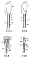
- Figs. 1 to 7, 9 and 10 illustrate different embodiments of the dental post provided with cross threads.
- Fig. 1 shows a side view of a dental post generally denoted at 10 and including an elongated cylindrical body portion 12 and a head portion 14. Two helical threads 18 and 20 extending in opposite directions and crossing each other are formed about a peripheral surface of the body portion 12 as will be explained in detail below.
- the head portion 14 includes a substantially conical neck 22 which supports a flattened head 24 terminated with an upwardly tapering tip portion 26.
- a plurality of horizontal ribs 30 vertically spaced from each other are provided on the external surface of head portion 14.
- An annular collar 32 interconnects the neck 22 and the body portion 12 of the dental post.
- the structure of the head portion 14 formed as a flattened tang member is known and has been disclosed in U.S. patent 4,571,187.
- a first spiral thread designated at 18 extends in one direction indicated by arrow A whereas a second spiral thread 20 extends in the direction of arrow B which is opposite to that of thread 18.
- Grooves or depressions 40 between lands 42 formed by the cross threads 18 and 20 form the cement containing regions, the overall area of which constitutes 60% of the entire peripheral surface of the body portion 12 of the dental post while the remaining 40% to the peripheral surface of body portion 12 are taken by lands 42.
- the pitch of each thread 18, 20 as well as the depth of depressions 40 can be changed depending on requirements.
- Fig. 2 shows the embodiment of the dental post 10 with two cross threads 18,20 formed on its body portion 12 and the head portion 14, an upper portion 14a of which is substantially oval and which is reduced in cross-section in the direction towards the body portion 12.
- the oval-shaped portion 14a of the head is adjoined with a substantially cylindrical lower portion 14b which merges into body portion 12 of the dental post.
- the body portion is stepped with the upper step 10a being of larger diameter than the lower step 10b.
- the same cross thread is on both steps.
- the cylindrical portion 14b forms yet a wider step but is unthreaded.
- the dental post with two cross-threads 18, 20 on body portion 12 thereof has a flattened head 14 which has one portion 14a of a reduced cross-section and another portion 14b of an enlarged cross-section.
- Figs. 5 and 6 show the body portion with depressions 40 and lands 42 similar to the aforedescribed embodiments and the head portion 14 the shape of which conforms to the anatomical shape of the dental restoration which is to be supported on the dental post.
- An undercut 15 for retaining cement is formed at the transition between the head portion 14 and the body portion 12.
- Head portion 14 has no sharp edges and is wider than body portion 12 in the mesio-distal orientation and the labial-lingual orientation as well.
- lands 42 which limit therebetween a larger surface of depressions or grooves 40 are also formed by two cross-threads 18 and 20 schematically shown in Fig. 7.
- the head portion 14 of the dental post in this embodiment includes a substantially cylindrical section 14b joining the stepped body portion 12 of the dental post and a substantially oval-shaped section 14a having a reduced diameter throat 14c of circular cross-section which is joined with the cylindrical section 14b.
- the surface area occupied by depressions 40 is by about 20% greater than the overall surface area of lands 42.
- Cement adheres not only within the grooves or depressions 40, but is also provided about the entire periphery of the post and also provides a layer about the peripheral surfaces of lands 42. Effectively the layer of cement is continuous about the post periphery with thin layers about the lands and thicker layers in the grooves.
- the spacing between lands 42 formed by two threads 18 and 20 crossing each other not only serves to retain a large continuous portion of cement but also provides a venting path 50 to allow air to escape along that path from the bore in the tooth stub as the dental post is inserted into that bore.
- the venting path 50 formed between lands 42 is made during the producing of the cross-threads, without requiring any additional operations.
- the pitch of threads 18 and 20 can be selected so that substantially rhombic lands 42 may be formed, which are elongated in the direction of the axis of the body portion 12. Two approximately axial natural venting paths would result from the cross-threads of this embodiment.
- wide open spaces are formed between lands 42 in all the embodiments disclosed herein. These wide open spaces are capable of retaining large segments of the thicker part of the continuous layer of cement, which segments are wedged in between lands 42 and are interlocked there.
- the depth of grooves or depressions 40 form wide spaces sufficient to permit cement to enter into these grooves and be reliably held between the bore formed in the tooth stub and the outer surface of the dental post.
- the greater space of the cross-threads as opposed to conventional helical flutes ensures that larger segments of cement can be adhered to the surface of the dental post, which significantly improves cement retention of the post within the bore of the tooth stub. It has been found that it is such large segments of cement which aids in retention.
- a further advantage of the two crossing threads on the outer surface of the dental post resides in that these threads form a reliable mechanism for preventing rotation of the dental post within the bore in each of the two opposite rotational directions. This increase in effective resistance to rotational torque aids in the retentive qualities of the post.
- a burnout post is a temporary plastic post normally used during the casting of a permanent dental post.
- the dental post will be cast in a like manner with wide open spaces between the lands.
- the dental post 10 with cross threads 18 and 20 is inserted into a bore 60 formed in the tooth stub 62.
- a space formed between the inner surface of bore 60 and the lands 42 at the periphery of the post is filled with cement.
- the cement forms thicker segments in the wide open grooves formed by depressions 40 between lands 42 of the cross-threads on the dental post 10. This cement secures the dental post 10 in the tooth stub 62.
- a dental core 66 is then built up on the head portion 14 of the dental post, extending outwardly from tooth stub to support thereon the dental restoration 68.
- the entire land portion is non-continous in all the embodiments while the groove protion is formed to retain a large continuous portion of cement.
- lands 42 can be of a shape or configuration such as rhombic, trapezoidal or square as long as the ratio between the overall solid portion and the overall groove portion on the outer surface of the body portion of the dental post is in the range of 3:2.
- Cross threads on the dental posts of the embodiments of Figs. 1-7, 9 and 10 can be produced on screw machines or by EDM-thread rolling dies, cold forming, casting or molding, or by cutters.
- the pitch and/or depth of each thread can be altered so that the groove portion of the outer surface of the body portion can be adjusted.
- the post can be threaded by moving it axially in one direction through the screw machine and then axially reversing its direction through the screw machine for forming the opposing threads.
Landscapes
- Health & Medical Sciences (AREA)
- Oral & Maxillofacial Surgery (AREA)
- Dentistry (AREA)
- Epidemiology (AREA)
- Life Sciences & Earth Sciences (AREA)
- Animal Behavior & Ethology (AREA)
- General Health & Medical Sciences (AREA)
- Public Health (AREA)
- Veterinary Medicine (AREA)
- Dental Tools And Instruments Or Auxiliary Dental Instruments (AREA)
- Dental Prosthetics (AREA)
- Dental Preparations (AREA)
Claims (19)
- Dentalstift (10) zum Verankern einer dentalen Restaurierung (68) in gesicherter Stellung, wobei der Dentalstift (10) derart ausgelegt ist, daß er in eine Bohrung (60) des Zahnstumpfes (62) eineführt werden kann, und wobei der Dentalstift (10) umfaßt:- einen länglichen, im wesentlichen zylindrischen Körperabschnitt (12) mit einer Außenfläche;- einen sich vom Körperabschnitt (12) erstreckenden Kopfabschnitt (14), der sich aus dem Zahnstumpf (62) nach außen erstreckt, um darauf die dentale Restaurierung (68) zu tragen, wenn der Körperabschnitt (12) in die Zahnstumpfbohrung (60) eingeführt ist; und- auf der Außenfläche angeordnete Zementverankerungs- bzw. -haltemittel, wobei die Außenfläche mit mehreren hervorstehenden Bereichen (42) versehen ist, welche auf der Außenfläche einen erhabenen Abschnittsbereich ausbilden und voneinander in Richtung der Längsachse des Körperabschnittes (12) wie auch in einer Richtung transversal zu der Längsrichtung voneinander beabstandet sind, um dazwischen einen nutenartigen Abschnittsbereich (40) auszubilden, wobei der erhabene Abschnittsbereich (42) und der nutenartige Abschnittsbereich (40) durch zwei auf den Außenflächen vorgesehene sich kreuzende Gewinde bzw. Kreuzgewinde ausgebildet sind und sich in einenander kreuzende Richtungen erstrecken, dadurch gekennzeichnet, daß das Verhältnis zwischen dem nutenartigen Abschnittsbereich (40) und dem erhabenen Abschnittsbereich (42) sich in einem Bereich von 60 : 40 % bewegt.
- Dentalstift nach Anspruch 1, dadurch gekennzeichnet, daß die hervorstehenden Bereiche (42) auf der Oberfläche in Reihen angeordnet sind.
- Dentalstift nach Anspruch 1 oder 2, dadurch gekennzeichnet, daß die Ganghöhe eines jeden Gewindes einstellbar ist, um das Verhältnis zwischen dem nutenartigen Abschnittsbereich (40) und dem erhabenen Abschnittsbereich (42) einzustellen.
- Dentalstift nach Anspruch 1 oder 2, dadurch gekennzeichnet, daß die Tiefe jedes Gewindes einstellbar ist, um das Verhältnis zwischen dem nutenartigen Abschnittsbereich (40) und dem erhabenen Abschnittsbereich (42) einzustellen.
- Dentalstift nach Anspruch 1 oder 2, dadurch gekennzeichnet, daß die erhabenen Abschnittsbereiche (42) voneinander beabstandet sind, um zwischeneinander wenigstens eine Entlüftung für Luft einzuschließen, welche aus der Bohrung (60) des Zahnstumpfes (62) entweicht, wenn der Körperabschnitt (12) in die Bohrung (60) einzementiert wird.
- Dentalstift nach Anspruch 1 oder 2, dadurch gekennzeichnet, daß der Kopfabschnitt (14) ein abgeflachtes Griffteil aufweist.
- Dentalstift nach Anspruch 1 oder 2, dadurch gekennzeichnet, daß der Kopfabschnitt (14) im wesentlichen ovalen Querschnitt aufweist.
- Dentalstift nach Anspruch 1 oder 2, dadurch gekennzeichnet, daß der Kopfabschnitt (14) abgeflacht ist.
- Dentalstift nach Anspruch 1 oder 2, dadurch gekennzeichnet, daß der Kopfabschnitt (14) eine Ausbildung aufweist, welche einer anatomischen Form der dentalen Restaurierung (68) entspricht.
- Dentalstift nach Anspruch 1, dadurch geknnzeichnet, daß der Körperabschnitt (14) abgestuft ist.
- Dentalstift nach Anspruch 3, dadurch gekennzeichnet, daß der Körperabschnitt (14) abgestuft ist.
- Dentalstift nach einem der Ansprüche 1-11, dadurch gekennzeichnet, daß die hervorstehenden Bereiche (42) im wesentlichen rhombische Form aufweisen.
- Dentalstift nach Anspruch 1-12, dadurch gekennzeichnet, daß die hervorstehenden Bereiche (42) im wesentlichen quadratische Form aufweisen.
- Verfahren zur Herstellung von Dentalstiften der Art mit einem länglichen, im wesentlichen zylindrischen Körperabschnitt und einem Kopfabschnitt zum Tragen einer dentalen Restaurierung, der sich von dem Körperabschnitt nach außen erstreckt, wobei der Körperabschnitt in einer Bohrung eines Zahnstumpfes mittels Zement befestigt wird, und auf einer Oberfläche des Körperabschnittes hervorstehende Bereiche ausgebildet werden, die voneinander beabstandet sind in einer Richtung einer Längsachse des Körperabschnittes und ebenso in einer Richtung transversal zu der Längsachse mittels weit offener Nuten zur Aufnahme bzw. Verankerung von Zement, wobei die Nuten durch zwei sich kreuzende Gewinde ausgebildet sind, dadurch gekennzeichnet, daß das Verhältnis zwischen einem gesamten Nutenbereich und einem gesamten Bereich der hervorstehenden Abschnitte auf der Oberfläche sich im Bereich von 60:40 % bewegt.
- Verfahren nach Anspruch 14, dadurch gekennzeichnet, daß die Ganghöhe der sich kreuzenden Gewinde bzw. Kreuzgewinde geändert werden kann.
- Verfahren nach Anspruch 14, dadurch gekennzeichnet, daß die Tiefe der Gewinde geändert werden kann.
- Verfahren nach Anspruch 14, dadurch gekennzeichnet, daß die Gewinde mittels Gewindewälzen ausgebildet werden.
- Verfahren nach Anspruch 14, dadurch gekennzeichnet, daß die Gewinde mittels Kaltverformen ausgebildet werden.
- Verfahren nach Anspruch 14, dadurch gekennzeichnet, daß die Gewinde mittels Schneiden ausgebildet werden.
Applications Claiming Priority (3)
| Application Number | Priority Date | Filing Date | Title |
|---|---|---|---|
| US233679 | 1988-08-18 | ||
| US07/233,679 US4932870A (en) | 1988-08-18 | 1988-08-18 | Dental post and method for making the same |
| PCT/US1989/003201 WO1990001908A1 (en) | 1988-08-18 | 1989-07-26 | Dental post and method for making the same |
Publications (3)
| Publication Number | Publication Date |
|---|---|
| EP0387334A1 EP0387334A1 (de) | 1990-09-19 |
| EP0387334A4 EP0387334A4 (en) | 1991-04-03 |
| EP0387334B1 true EP0387334B1 (de) | 1994-06-08 |
Family
ID=22878256
Family Applications (1)
| Application Number | Title | Priority Date | Filing Date |
|---|---|---|---|
| EP89910342A Expired - Lifetime EP0387334B1 (de) | 1988-08-18 | 1989-07-26 | Dentalstift und verfahren zur herstellung |
Country Status (7)
| Country | Link |
|---|---|
| US (1) | US4932870A (de) |
| EP (1) | EP0387334B1 (de) |
| AT (1) | ATE106704T1 (de) |
| AU (1) | AU611371B2 (de) |
| CA (1) | CA1324901C (de) |
| DE (1) | DE68916005T2 (de) |
| WO (1) | WO1990001908A1 (de) |
Cited By (1)
| Publication number | Priority date | Publication date | Assignee | Title |
|---|---|---|---|---|
| US9089384B1 (en) | 2013-05-21 | 2015-07-28 | Austin H. Sampson | Dental pin system |
Families Citing this family (13)
| Publication number | Priority date | Publication date | Assignee | Title |
|---|---|---|---|---|
| US5145373A (en) * | 1989-02-09 | 1992-09-08 | Roane James B | Endodontic post |
| US5088926A (en) * | 1990-01-05 | 1992-02-18 | Manfred Lang | Implant for the jawbone |
| SE464959B (sv) * | 1990-01-18 | 1991-07-08 | Nobelpharma Ab | Avtryckstopp utfoerd i elastiskt material |
| US5094618A (en) * | 1991-04-26 | 1992-03-10 | Coltene/Whaledent, Inc. | Intermittent threaded dental posts |
| CH685281A5 (fr) * | 1991-07-02 | 1995-05-31 | Maillefer Instr Sa | Instrument pour l'art dentaire servant au traitement des canaux radiculaires. |
| US5348476A (en) * | 1993-11-24 | 1994-09-20 | Essential Dental Systems, Inc. | System for fabrication of dental cast post and core using a burn-out post |
| US5427526A (en) * | 1993-12-13 | 1995-06-27 | Fernandes; Americo | Dental implant and dentistry implant method |
| US6186791B1 (en) | 1998-08-11 | 2001-02-13 | Jeneric/Pentron Incorporated | Fiber reinforced composite post |
| US7488175B2 (en) * | 1998-08-11 | 2009-02-10 | Pentron Clinical Technologies, Llc | Fiber reinforced composite post |
| USD461559S1 (en) | 2000-11-06 | 2002-08-13 | Coltene/Whaledent, Inc. | Core form |
| DE102005021807B3 (de) * | 2005-05-04 | 2006-11-30 | Universität Rostock | Isoelastischer Endodontiestift |
| BRMU8900506U2 (pt) * | 2009-03-12 | 2010-11-30 | Geninho Thome | parafuso de fixação para componentes protéticos na implantodontia |
| US20140030674A1 (en) * | 2012-01-27 | 2014-01-30 | Hao Nguyen | Prefabricated immediate no-drill dental implant |
Family Cites Families (8)
| Publication number | Priority date | Publication date | Assignee | Title |
|---|---|---|---|---|
| US1517500A (en) * | 1924-01-05 | 1924-12-02 | Enoch M Fredericks | Artificial crown for teeth and securing means therefor |
| US2536669A (en) * | 1947-07-29 | 1951-01-02 | Thau-Jensen Orla | Root pin for use in reinforcement in lays, cast crowns, and pivot teeth |
| SU843972A1 (ru) * | 1976-04-12 | 1981-07-07 | Иркутский Государственный Медицинскийинститут | Штифт дл искусственной коронки |
| DE2619650C3 (de) * | 1976-05-04 | 1985-06-05 | Friedrichsfeld Gmbh, Steinzeug- Und Kunststoffwerke, 6800 Mannheim | Dentalimplantat |
| US4767332A (en) * | 1981-12-03 | 1988-08-30 | Ipco Corporation | Threaded dental anchor |
| US4474556A (en) * | 1982-10-13 | 1984-10-02 | Carbomedics, Inc. | Dental implant |
| US4729736A (en) * | 1986-09-08 | 1988-03-08 | Ipco Corporation | Contoured dental posts |
| US4820159A (en) * | 1987-07-23 | 1989-04-11 | Ipco Corporation | Dental post and core assembly |
-
1988
- 1988-08-18 US US07/233,679 patent/US4932870A/en not_active Expired - Lifetime
-
1989
- 1989-07-26 DE DE68916005T patent/DE68916005T2/de not_active Expired - Fee Related
- 1989-07-26 EP EP89910342A patent/EP0387334B1/de not_active Expired - Lifetime
- 1989-07-26 WO PCT/US1989/003201 patent/WO1990001908A1/en not_active Ceased
- 1989-07-26 AU AU42204/89A patent/AU611371B2/en not_active Ceased
- 1989-07-26 AT AT89910342T patent/ATE106704T1/de not_active IP Right Cessation
- 1989-08-07 CA CA000607689A patent/CA1324901C/en not_active Expired - Lifetime
Cited By (1)
| Publication number | Priority date | Publication date | Assignee | Title |
|---|---|---|---|---|
| US9089384B1 (en) | 2013-05-21 | 2015-07-28 | Austin H. Sampson | Dental pin system |
Also Published As
| Publication number | Publication date |
|---|---|
| DE68916005D1 (de) | 1994-07-14 |
| EP0387334A1 (de) | 1990-09-19 |
| US4932870A (en) | 1990-06-12 |
| ATE106704T1 (de) | 1994-06-15 |
| CA1324901C (en) | 1993-12-07 |
| AU4220489A (en) | 1990-03-23 |
| DE68916005T2 (de) | 1994-12-22 |
| WO1990001908A1 (en) | 1990-03-08 |
| AU611371B2 (en) | 1991-06-06 |
| EP0387334A4 (en) | 1991-04-03 |
Similar Documents
| Publication | Publication Date | Title |
|---|---|---|
| EP0536386B1 (de) | Dentalstift mit intermittierendem gewinde | |
| US4932870A (en) | Dental post and method for making the same | |
| EP0984737B1 (de) | Support zum halten und/oder bilden eines zahnersatzes | |
| EP1161197B1 (de) | Selbstbohrendes implantat | |
| CA2093900C (en) | Dental implant having cutting means | |
| US5772437A (en) | Securing element | |
| US4871313A (en) | Dental pin | |
| US4479783A (en) | Helically fluted dental post | |
| US6149432A (en) | Buttress thread dental implant | |
| DE102012105873A1 (de) | Zahnimplantat | |
| KR20210072068A (ko) | 치과용 임플란트 나사산 | |
| WO1989010726A1 (en) | Threaded dental anchor | |
| EP0260446B1 (de) | Geformter Zahnwurzelstift | |
| CA1208051A (en) | Dental anchor | |
| US4708655A (en) | Contoured dental post and drill jig for use therewith | |
| US4894064A (en) | Endoprosthesis for a hip-joint socket | |
| JP7626313B2 (ja) | 改善されたセルフタッピング歯科インプラント | |
| US5820375A (en) | Dental post having cutting and non-cutting surfaces | |
| EP0455727A4 (en) | Dental anchor and drill for use therewith | |
| CA1324900C (en) | Dental post for retention of dental restoration | |
| EP1145691A1 (de) | Zahnimplantat mit einem Sägezahngewinde | |
| EP1326551B1 (de) | Implantat mit rillenstruktur | |
| JP3026125U (ja) | 歯科用インプラント | |
| DE102004017344A1 (de) | Dentalimplantat mit Außengewinde | |
| WO2001037753A1 (en) | Instrument (osteotome) for forming holes in bone tissue, preferably in jaw-bone tissue |
Legal Events
| Date | Code | Title | Description |
|---|---|---|---|
| PUAI | Public reference made under article 153(3) epc to a published international application that has entered the european phase |
Free format text: ORIGINAL CODE: 0009012 |
|
| AK | Designated contracting states |
Kind code of ref document: A1 Designated state(s): AT BE CH DE FR GB IT LI LU NL SE |
|
| 17P | Request for examination filed |
Effective date: 19900824 |
|
| RAP1 | Party data changed (applicant data changed or rights of an application transferred) |
Owner name: IPCO CORPORATION |
|
| A4 | Supplementary search report drawn up and despatched |
Effective date: 19910214 |
|
| AK | Designated contracting states |
Kind code of ref document: A4 Designated state(s): AT BE CH DE FR GB IT LI LU NL SE |
|
| 17Q | First examination report despatched |
Effective date: 19920923 |
|
| GRAA | (expected) grant |
Free format text: ORIGINAL CODE: 0009210 |
|
| RAP1 | Party data changed (applicant data changed or rights of an application transferred) |
Owner name: COLTENE/WHALEDENT, INC. |
|
| AK | Designated contracting states |
Kind code of ref document: B1 Designated state(s): AT BE CH DE FR GB IT LI LU NL SE |
|
| PG25 | Lapsed in a contracting state [announced via postgrant information from national office to epo] |
Ref country code: LI Effective date: 19940608 Ref country code: CH Effective date: 19940608 Ref country code: AT Effective date: 19940608 Ref country code: IT Free format text: LAPSE BECAUSE OF FAILURE TO SUBMIT A TRANSLATION OF THE DESCRIPTION OR TO PAY THE FEE WITHIN THE PRE;WARNING: LAPSES OF ITALIAN PATENTS WITH EFFECTIVE DATE BEFORE 2007 MAY HAVE OCCURRED AT ANY TIME BEFORE 2007. THE CORRECT EFFECTIVE DATE MAY BE DIFFERENT FROM THE ONE RECORDED.SCRIBED TIME-LIMIT Effective date: 19940608 Ref country code: NL Effective date: 19940608 Ref country code: FR Effective date: 19940608 Ref country code: BE Effective date: 19940608 |
|
| REF | Corresponds to: |
Ref document number: 106704 Country of ref document: AT Date of ref document: 19940615 Kind code of ref document: T |
|
| REF | Corresponds to: |
Ref document number: 68916005 Country of ref document: DE Date of ref document: 19940714 |
|
| PG25 | Lapsed in a contracting state [announced via postgrant information from national office to epo] |
Ref country code: LU Free format text: LAPSE BECAUSE OF NON-PAYMENT OF DUE FEES Effective date: 19940731 |
|
| PG25 | Lapsed in a contracting state [announced via postgrant information from national office to epo] |
Ref country code: SE Effective date: 19940908 |
|
| REG | Reference to a national code |
Ref country code: CH Ref legal event code: PL |
|
| EN | Fr: translation not filed | ||
| NLV1 | Nl: lapsed or annulled due to failure to fulfill the requirements of art. 29p and 29m of the patents act | ||
| PLBE | No opposition filed within time limit |
Free format text: ORIGINAL CODE: 0009261 |
|
| STAA | Information on the status of an ep patent application or granted ep patent |
Free format text: STATUS: NO OPPOSITION FILED WITHIN TIME LIMIT |
|
| 26N | No opposition filed | ||
| REG | Reference to a national code |
Ref country code: GB Ref legal event code: IF02 |
|
| PGFP | Annual fee paid to national office [announced via postgrant information from national office to epo] |
Ref country code: GB Payment date: 20050720 Year of fee payment: 17 |
|
| PGFP | Annual fee paid to national office [announced via postgrant information from national office to epo] |
Ref country code: DE Payment date: 20050831 Year of fee payment: 17 |
|
| PG25 | Lapsed in a contracting state [announced via postgrant information from national office to epo] |
Ref country code: GB Free format text: LAPSE BECAUSE OF NON-PAYMENT OF DUE FEES Effective date: 20060726 |
|
| PG25 | Lapsed in a contracting state [announced via postgrant information from national office to epo] |
Ref country code: DE Free format text: LAPSE BECAUSE OF NON-PAYMENT OF DUE FEES Effective date: 20070201 |
|
| GBPC | Gb: european patent ceased through non-payment of renewal fee |
Effective date: 20060726 |