EP0386531A2 - Folder - Google Patents
Folder Download PDFInfo
- Publication number
- EP0386531A2 EP0386531A2 EP90103371A EP90103371A EP0386531A2 EP 0386531 A2 EP0386531 A2 EP 0386531A2 EP 90103371 A EP90103371 A EP 90103371A EP 90103371 A EP90103371 A EP 90103371A EP 0386531 A2 EP0386531 A2 EP 0386531A2
- Authority
- EP
- European Patent Office
- Prior art keywords
- cylinder
- folding
- radial direction
- strips
- sections
- Prior art date
- Legal status (The legal status is an assumption and is not a legal conclusion. Google has not performed a legal analysis and makes no representation as to the accuracy of the status listed.)
- Granted
Links
Images


Classifications
-
- B—PERFORMING OPERATIONS; TRANSPORTING
- B65—CONVEYING; PACKING; STORING; HANDLING THIN OR FILAMENTARY MATERIAL
- B65H—HANDLING THIN OR FILAMENTARY MATERIAL, e.g. SHEETS, WEBS, CABLES
- B65H45/00—Folding thin material
- B65H45/12—Folding articles or webs with application of pressure to define or form crease lines
- B65H45/16—Rotary folders
- B65H45/162—Rotary folders with folding jaw cylinders
- B65H45/166—Rotary folders with folding jaw cylinders having an adjustable circumference
-
- B—PERFORMING OPERATIONS; TRANSPORTING
- B41—PRINTING; LINING MACHINES; TYPEWRITERS; STAMPS
- B41F—PRINTING MACHINES OR PRESSES
- B41F13/00—Common details of rotary presses or machines
- B41F13/54—Auxiliary folding, cutting, collecting or depositing of sheets or webs
- B41F13/56—Folding or cutting
- B41F13/62—Folding-cylinders or drums
Definitions
- the invention relates to a folding apparatus with at least two folding cylinders provided with interacting folding tools in the form of folding knives or folding flaps.
- the folding cylinders are placed against one another while maintaining a fixed gap through which the products to be manufactured must pass.
- the clear width of the gap is adapted to the product thickness and usually in such a way that there is a slight undersize compared to the product thickness, which is compensated for by the elasticity of an elastic cylinder support. This only leads to a certain product thickness satisfactory results.
- With a smaller product thickness there is no reliable contact on the cylinder surface.
- the greater product thickness results in a large bulge due to strong pressure in the area of the elastic support, which can lead to a displacement of the products.
- very great difficulties can arise here.
- At least one folding cylinder has circumferential sections which are adjustable in the radial direction at least in some areas.
- the measures according to the invention therefore enable the production of products with very different thicknesses and nevertheless guarantee the same production accuracy and product protection in every case.
- the measures according to the invention thus enable a not inconsiderable broadening of the area of use of a generic folding apparatus and thus result in an overall increase in economy.
- the folding cylinder provided with folding jaws can expediently have circumferential sections which are adjustable in the radial direction, since the length of the products resting on the folding jaw cylinder is shortened to half the length of the section as a result of the folding process. It is therefore sufficient if the peripheral area between the successive folding members is divided into two sections, of which only the section following the adjacent folding member is adjustable in the radial direction and the other is fixed.
- a further expedient measure can consist in the fact that the sections which can be adjusted in the radial direction have a spacing which is arranged next to one another and can be exhibited jointly in the radial direction and which are preferably provided with an elastic covering. This simplifies the structural design, since the strips can simply be arranged to be retractable and extendable. For this purpose, these can expediently be pivoted about a pivot axis parallel to the cylinder axis and provided in the area of the leading strip end.
- the strips can be slidably and tiltably received on a respective cylinder-fixed pin which is encompassed by a return spring and rest on the one hand on a cylinder-side support surface and on the other hand on an adjusting device provided on the cylinder.
- the actuating device can simply have an eccentric shaft which extends parallel to the cylinder parallel to the associated strips and which can be rotated by means of a rotating device and can be fixed by means of a clamping device, which ensures a simple and clear structure and a high level of user friendliness.
- all the eccentric shafts provided on a cylinder can be provided with side drive wheels, the drive wheels provided in the area of a cylinder end face being able to engage a common adjusting ring which is coaxial with the cylinder axis, which advantageously enables all eccentric shafts to be adjusted jointly .
- the structure and mode of operation of folders are known per se.
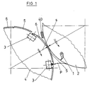
- the centerpiece of a folder is a transverse folder of the type on which the figure is based.
- This comprises a folder knife cylinder 2 provided with folder blades 1 and a folder cylinder 4 cooperating with folder blades 1.
- the two cylinders 2, 4 are driven in such a way that they meet at the same speed
- a gap s is provided between the two cylinders 2, 4, the inside width of which corresponds to the thickness of the unfolded product P or has a slight undersize, so that the product P passing through the gap s is reliably pressed against the surface of the folding knife cylinder 2.
- the clear width of the gap s can be adjusted.
- the circumferential areas between the successive folding flaps 3 are each divided into two sections 5, 6, of which the leading in the direction of rotation Section 5, that is, the section 5 adjacent to the folding flap 3 advancing in the direction of rotation can be adjusted at least with its rear end in the radial direction. This results in a change in the diameter of the folding jaw cylinder in the region of the peripheral sections 5, which prevents the gap s from being too large or too small.
- the adjustable circumferential sections 5 are formed by curved strips 7, which are uniformly distributed over the cylinder width and are arranged next to one another at a distance, which are provided with an elastic covering 8 and which can be opened together in the radial direction.
- strips 9, such as their covering 8, which are made of elastic material can be provided in the extension of the strips 7.
- the spaced-apart strips 7 are received in assigned circumferential slots 10 and can be extended or retracted from these. In the retracted state, the circumferential contour indicated in FIG. 2 results with dashed lines, which merges practically steplessly into the circumferential contour of the strips 9 which are fixedly arranged on the cylinder circumference.
- the strips 7 are pivoted out radially with their rear end in the direction of rotation, so that there is a step with respect to the adjacent, fixed strips 9.
- the resulting increase in diameter of the jaw cylinder 4 enables reliable pressing against the surface of the folder cylinder 2 even in the manufacture of very thin products.
- the strips 7 are swung out so far that the minimum gap width of the gap s when the rear ends of the strips 7 pass the adjacent folding blade cylinder 2 has an undersize of 0.5 mm compared to the product thickness, which is absorbed by deformation of the elastic strips 8.
- the strips 7, as can be seen in FIG. 2, are adjustable in the radial direction and can be tilted on a respectively assigned radial pin 11 arranged in a cylinder-fixed manner.
- the strips 7 are provided with a bracket 12 which is penetrated by the respectively assigned radial pin 11 and which is gripped behind by a chamber-shaped recess 13 into which the end of the respectively assigned radial pin 11 which carries a head 14 projects.
- the yoke 12 is provided with a bore 5 which is penetrated by the shaft of the associated radial pin 11 and which is oversized with respect to the shaft diameter, so that the respective strip 7 can tilt.
- the end of the radial pin 11 protruding into the recess 13 is encompassed by a plate spring assembly 16 which bears on the one hand on the head 14 and on the other hand on the yoke 12 which engages under the head 14.
- the strips 7 are each provided with a support foot 17 or 18.
- the front support leg 17 stands on a cylinder-side support surface 19.
- the rear support foot 18 bears against an eccentric shaft 20 which is parallel to the cylinder axis and which can be rotated in order to pivot out the strips 7 each forming an adjustable peripheral section 5.
- the plate spring 16 is compressed. This works demented speaking as a return spring.
- the eccentric shaft 20 which is parallel to the cylinder, passes through the entire cylinder width in the case of single-width cylinders, so that all strips 7 of an adjustable peripheral section 5, which are uniformly distributed over the cylinder width, can be adjusted together.
- the eccentric shaft 20, as can best be seen in FIG. 3, is received with eccentric collars 21 on roller bearings 22 which are mounted in an associated cylinder bore 23 close to the circumference.
- the eccentric shaft 20 is provided with a protruding square 24 in the region of a cylinder end face, to which a rotary key can be attached.
- the square 24 protrudes over a collar 25 serving as an axial bearing, which rests against the cylinder end face and which can be clamped by means of a clamping claw 26 to secure the set position.
- the collar 25 is designed as a scale carrier provided with a scale 27, which can cooperate with a marking provided on the cylinder side, for example in the form of a notch.
- the folding jaw cylinder 4 is provided with a plurality of folding jaws 3 on the circumference and accordingly with a plurality of adjustable circumferential sections 5, an actuating device assigned to all eccentric shafts can be provided to simplify the operation.
- the eccentric shafts 20, as can best be seen from FIG. 4 can each be provided with a lateral drive wheel 28, wherein all drive wheels 28 are in engagement with a common adjusting ring 29 arranged coaxially to the cylinder axis.
- this is provided with peripheral toothed strips 30, in each of which an associated drive wheel 28 engages.
- the toothed strips 30 are offset from one another by circumferential recesses 31, into which cassettes provided on the cylinder side engage to accommodate the folding jaws 3.
- the adjusting ring 29 arranged in the area of a cylinder end face is received on pins 32 on the cylinder side which engage in assigned arc slots 33. At least one of the pins 32 is designed as a clamping screw 32a, by means of which the adjusting ring 29 can be locked.
- the adjusting ring 29 can be turned by hand.
- the adjusting ring 29 is provided with a toothing 34 provided in the region of its inner circumference, into which engages an adjusting wheel 35 which is mounted in the region of the cylinder end face and which can be provided with a hexagon 36 for attaching a rotary key.
- FIG. 5 This is a double-width jaw cylinder with two cylinder sections 38a, b which can be operated next to one another on a common axis 37 and can be operated independently of one another.
- the strips 7 provided in the region of the two cylinder sections 38a, 38b, which can be retracted and extended in the radial direction, with elastic covering 8 can be operated independently of the strips of the adjacent cylinder section.
- the basic structure corresponds to the structure shown in FIG. 2, the eccentric shaft 20 not passing over the entire cylinder width, but only extending over the associated cylinder section 38a, b.
- the eccentric shafts 20 of the two cylinder sections 38a, b are provided with drive means in the region of the cylinder faces facing away from one another. These correspond to the embodiment according to FIG. 4, with the difference that the adjusting wheel 35 meshing with the adjusting ring 29 is driven by a respectively assigned drive motor 39, which is arranged here inside the cylinder or the respective cylinder section and attached to the relevant end wall from the inside is.
- peripheral portions 6 can tip out in the radial direction only with their rear end in the direction of rotation ensures that only the rear end of the products p, after being provided at the inlet to the gap between the cylinders 2, 4, in FIG 40 indicated guide means, such as brushes, tapes, etc. is no longer guided, pressed against the cylinders 2 and can thus be guided.
- guide means such as brushes, tapes, etc.
- the limitation of the contact pressure to the rear end of the product ensures that the flexing work to be taken up by the sections 6 remains limited and that the products are not damaged, such as a marking, etc.
Abstract
Description
Die Erfindung betrifft einen Falzapparat mit wenigstens zwei mit zusammenwirkenden Falzwerkzeugen in Form von Falzmessern bzw. Falzklappen versehenen Falzzylindern.The invention relates to a folding apparatus with at least two folding cylinders provided with interacting folding tools in the form of folding knives or folding flaps.
Bei den bekannten Anordnungen dieser Art sind die Falzzylinder unter Einhaltung eines feststehenden Spalts, durch den die herzustellenden Produkte hindurchgehen müssen, aneinander angestellt. Die lichte Weite des Spalts ist dabei der Produktdicke angepaßt und zwar normalerweise derart, daß sich gegenüber der Produktdicke ein leichtes Untermaß ergibt, das durch die Elastizität einer elastischen Zylinderauflage ausgeglichen wird. Dies führt nur bei einer bestimmten Produktdicke zu zu friedenstellenden Ergebnissen. Bei demgegenüber kleinerer Produktdicke ergibt sich keine zuverlässige Anlage an der Zylinderoberfläche. Bei demgegenüber größerer Produktdicke ergibt sich infolge starker Pressung im Bereich der elastischen Auflage ein großer Wulst, der zu einer Verschiebung der Produkte führen kann. Insbesondere bei doppelt breiten Apparaten mit zwei nebeneinander liegen Produktionslinien für unterschiedlich dicke Produkte können sich hier sehr große Schwierigkeiten auftun.In the known arrangements of this type, the folding cylinders are placed against one another while maintaining a fixed gap through which the products to be manufactured must pass. The clear width of the gap is adapted to the product thickness and usually in such a way that there is a slight undersize compared to the product thickness, which is compensated for by the elasticity of an elastic cylinder support. This only leads to a certain product thickness satisfactory results. In contrast, with a smaller product thickness, there is no reliable contact on the cylinder surface. In contrast, the greater product thickness results in a large bulge due to strong pressure in the area of the elastic support, which can lead to a displacement of the products. Particularly in the case of double-width devices with two adjacent production lines for products of different thicknesses, very great difficulties can arise here.
Hiervon ausgehend ist es daher die Aufgabe der vorliegenden Erfindung einen Falzapparat eingangs erwähnter Art so zu verbessern, daß die wirksame Spaltweite an die unterschiedliche Dicke verschiedener Produkte angepaßt werden kann.Proceeding from this, it is therefore the object of the present invention to improve a folder of the type mentioned at the outset in such a way that the effective gap width can be adapted to the different thickness of different products.
Diese Aufgabe wird erfindungsgemäß dadurch gelöst, daß wenigstens ein Falzzylinder Umfangsabschnitte aufweist, die zumindest bereichsweise in radialer Richtung verstellbar sind.This object is achieved in that at least one folding cylinder has circumferential sections which are adjustable in the radial direction at least in some areas.
Mit diesen Maßnahmen lassen sich die eingangs geschilderten Nachteile vollständig beseitigen. Die erfindungsgemäßen Maßnahmen ermöglichen daher die Herstellung von Produkten mit sehr unterschiedlicher Dicke und gewährleisten dennoch in jedem Falle dieselbe Produktionsgenauigkeit und Produktschonung. Die erfindungsgemäßen Maßnahmen ermöglichen somit eine nicht unbeträchtliche Verbreiterung des Einsatzgebiets eines gattungsgemäßen Falzapparats und ergeben somit insgesamt eine Steigerung der Wirtschaftlichkeit.With these measures, the disadvantages described above can be completely eliminated. The measures according to the invention therefore enable the production of products with very different thicknesses and nevertheless guarantee the same production accuracy and product protection in every case. The measures according to the invention thus enable a not inconsiderable broadening of the area of use of a generic folding apparatus and thus result in an overall increase in economy.
Zweckmäßig kann der mit Falzklappen versehene Falzzylinder in radialer Richtung verstellbare Umfangsabschnitte aufweisen, da sich die Länge der auf dem Falzklappenzylinder aufliegenden Produkte infolge des Falzvorgangs auf die halbe Abschnittlänge verkürzt. Es genügt daher, wenn der Umfangsbereich zwischen den aufeinanderfolgenden Falzorganen in zwei Abschnitte unterteilt ist, von denen lediglich der dem benachbarten Falzorgan nachlaufende Abschnitt in radialer Richtung verstellbar und der andere fest angeordnet ist.The folding cylinder provided with folding jaws can expediently have circumferential sections which are adjustable in the radial direction, since the length of the products resting on the folding jaw cylinder is shortened to half the length of the section as a result of the folding process. It is therefore sufficient if the peripheral area between the successive folding members is divided into two sections, of which only the section following the adjacent folding member is adjustable in the radial direction and the other is fixed.
Eine weitere zweckmäßige Maßnahme kann darin bestehen, daß die in radialer Richtung verstellbaren Abschnitte mit Abstand nebeneinander angeordnete, gemeinsam in radialer Richtung ausstellbare Leistung aufweisen, die vorzugsweise mit einem elastischen Belag versehen sind. Dies vereinfacht die bauliche Ausführung, da einfach die Leisten ein- und ausfahrbar angeordnet werden können. Hierzu können diese zweckmäßig um eine zylinderachsparallele, im Bereich des vorlaufenden Leistenendes vorgesehene Schwenkachse schwenkbar angeordnet sein.A further expedient measure can consist in the fact that the sections which can be adjusted in the radial direction have a spacing which is arranged next to one another and can be exhibited jointly in the radial direction and which are preferably provided with an elastic covering. This simplifies the structural design, since the strips can simply be arranged to be retractable and extendable. For this purpose, these can expediently be pivoted about a pivot axis parallel to the cylinder axis and provided in the area of the leading strip end.
Vorteilhaft können die Leisten auf einem jeweils zugeordneten, von einer Rückstellfeder umfaßten, zylinderfesten Stift in radialer Richtung verschiebbar und kippbar aufgenommen sein und einerseits an einer zylinderseitigen Stützfläche und andererseits an einer auf den Zylinder vorgesehenen Stelleinrichtung anliegen. Diese Maßnahmen ergeben einen besonders einfachen und robusten Aufbau und gewährleisten gleichzeitig eine einfache Bedienbarkeit.Advantageously, the strips can be slidably and tiltably received on a respective cylinder-fixed pin which is encompassed by a return spring and rest on the one hand on a cylinder-side support surface and on the other hand on an adjusting device provided on the cylinder. These measures result in a particularly simple and robust construction and, at the same time, ensure simple operability.
Die Stelleinrichtung kann einfach eine zylinderachsparallel über die zugeordneten Leisten sich erstreckende Exzenterwelle aufweisen, die mittels einer Dreheinrichtung verdrehbar und mittels einer Klemmeinrichtung feststellbar ist, was einen einfachen und übersichtlichen Aufbau sowie eine hohe Bedienungsfreundlichkeit gewährleistet.The actuating device can simply have an eccentric shaft which extends parallel to the cylinder parallel to the associated strips and which can be rotated by means of a rotating device and can be fixed by means of a clamping device, which ensures a simple and clear structure and a high level of user friendliness.
In weiterer Fortbildung der übergeordneten Maßnahmen können sämtliche auf einem Zylinder vorgesehene Exzenterwellen mit seitlichen Antriebsrädern versehen sein, wobei die im Bereich einer Zylinderstirnseite vorgesehenen Antriebsräder mit einem gemeinsamen, zur Zylinderachse koaxialen Stellring im Eingriff sein können, was in vorteilhafter Weise eine gemeinsame Verstellbarkeit sämtlicher Exzenterwellen ermöglicht.In a further development of the superordinate measures, all the eccentric shafts provided on a cylinder can be provided with side drive wheels, the drive wheels provided in the area of a cylinder end face being able to engage a common adjusting ring which is coaxial with the cylinder axis, which advantageously enables all eccentric shafts to be adjusted jointly .
Weitere vorteilhafte Ausgestaltungen und zweckmäßige Fortbildungen der übergeordneten Maßnahmen ergeben sich aus den restlichen Unteransprüchen.Further advantageous refinements and expedient further training of the superordinate measures result from the remaining subclaims.
Nachstehend wird ein Ausführungsbeispiel der Erfindung anhand der Zeichnung näher erläutert. In der Zeichnung zeigen:
Figur 1 eine Teilseitenansicht eines aus Falzmesserzylinder und Falzklappenzylinder bestehenden Querfalzwerks,Figur 2 eine Teilstirnansicht des Falzklappenzylinders teilweise im Schnitt,Figur 3 einen Teillängsschnitt durch den Falzklappenzylinder derFigur 2,Figur 4 eine Stirnansicht eines mit einem Stellring versehenen Falzklappenzylinders undFigur 5 einen Längsschnitt durch einen doppelt breiten, erfindungsgemäßen Falzklappen-Zylinder.
- FIG. 1 shows a partial side view of a transverse folding unit consisting of a folding knife cylinder and folding jaw cylinder,
- FIG. 2 shows a partial end view of the folding jaw cylinder, partly in section,
- FIG. 3 shows a partial longitudinal section through the folding jaw cylinder of FIG. 2,
- Figure 4 is an end view of a jaw cylinder provided with an adjusting ring
- Figure 5 shows a longitudinal section through a double-width, jaw cylinder according to the invention.
Der Aufbau und die Wirkungsweise von Falzapparaten sind an sich bekannt. Kernstück eines Falzapparats ist ein Querfalzwerk der der Figur zugrundeliegenden Art. Dieses umfaßt einen mit Falzmessern 1 versehenen Falzmesserzylinder 2 und einen mit den Falzmessern 1 zusammenwirkenden Falzklappen 3 versehenen Falzklappenzylinder 4. Die beiden Zylinder 2, 4 werden so angetrieben, daß sie mit gleicher Geschwindigkeit aufeinander abrollen.Zwischen den beiden Zylindern 2, 4 ist ein Spalt s vorgesehen, dessen lichte Weite der Dicke des ungefalzten Produkte P entspricht oder demgegenüber leichtes Untermaß besitzt, so daß das den Spalt s durchlaufende Produkte P zuverlässig an die Oberfläche des Falzmesserzylinders 2 angedrückt wird.The structure and mode of operation of folders are known per se. The centerpiece of a folder is a transverse folder of the type on which the figure is based. This comprises a
Um Produkte unterschiedlicher Dicke verarbeiten zu können, ist die lichte Weite des Spalts s einstellbar. Hierzu sind die Umfangsbereiche zwischen den aufeinanderfolgenden Falzklappen 3 jeweils in zwei Abschnitte 5, 6 unterteilt, von denen der in Drehrichtung vorlaufende Ab schnitt 5, das heißt der der in Drehrichtung vorlaufenden Falzklappe 3 benachbarte Abschnitt 5 zumindest mit seinem hinteren Ende in radialer Richtung verstellbar ist. Hierdurch ergibt sich eine Durchmesserveränderung des Falzklappenzylinders im Bereich der Umfangsabschnitte 5, die verhindert, daß der Spalt s zu groß oder zu klein ist.In order to be able to process products of different thicknesses, the clear width of the gap s can be adjusted. For this purpose, the circumferential areas between the
Die verstellbaren Umfangsabschnitte 5 werden, wie aus den Figuren 2 und 3 erkennbar ist, durch gleichmäßig über die Zylinderbreite verteilte, mit Abstand nebeneinander angeordnete, gebogene Leisten 7 gebildet, die mit einem elastischen Belag 8 versehen sind und die gemeinsam in radialer Richtung ausstellbar sind. Im Bereich der stationären Umfangsabschnitte 6 können in Verlängerung der Leisten 7 vorgesehene, wie deren Belag 8 aus elastischem Material bestehende Streifen 9 vorgesehen sein. Die voneinander beabstandeten Leisten 7 sind in zugeordneten Umfangsschlitzen 10 aufgenommen und aus diesen ausfahrbar bzw. in diese einfahrbar. Im eingefahrenen Zustand ergibt sich die in Figur 2 mit gestrichelten Linien angedeutete Umfangskontur, die praktisch stufenlos in die Umfangskontur der fix auf den Zylinderumfang angeordneten Streifen 9 übergeht. In der in Figur 2 mit durchgezogenen Linien angedeuteten, ausgefahrenen Stellung sind die Leisten 7 mit ihrem in Drehrichtung hinteren Ende radial ausgeschwenkt, so daß sich gegenüber den benachbarten, fixen Streifen 9 eine Stufe ergibt. Die so bewirkte Durchmesservergrößerung des Falzklappenzylinders 4 ermöglicht auch bei der Herstellung sehr dünner Produkte eine zuverlässige Anpressung an die Oberfläche des Falzmesserzylinders 2.As can be seen from FIGS. 2 and 3, the adjustable
Üblicherweise werden die Leisten 7 so weit ausgeschwenkt, daß die minimale Spaltweite des Spalts s beim Vorbeigang der hinteren Enden der Leisten 7 am benachbarten Falzmesserzylinder 2 gegenüber der Produktdicke ein Untermaß von 0,5 mm aufweist, das durch Verformung der elastischen Streifen 8 aufgenommen wird.Usually, the
Die Leisten 7 sind, wie Figur 2 weiter erkennen läßt, in radiaier Richtung verstellbar und kippbar auf einem jeweils zugeordneten, zylinderfest angeordneten Radialstift 11 aufgenommen. Hierzu sind die Leisten 7 mit einem vom jeweils zugeordneten Radialstift 11 durchgriffenen Bock 12 versehen, der von einer kammerförmigen Ausnehmung 13 hintergriffen ist, in die das einen Kopf 14 tragende Ende des jeweils zugeordneten Radialstifts 11 hineinragt. Das Joch 12 ist mit einer vom Schaft des zugeordneten Radialstifts 11 durchgriffenen Bohrung 5 versehen, die gegenüber dem Schaftdurchmesser Übermaß besitzt, so daß die jeweilige Leiste 7 kippen kann. Das in die Ausnehmung 13 hineinragende Ende des Radialstifts 11 ist von einem Tellerfederpaket 16 umfaßt, das einerseits am Kopf 14 und andererseits an dem den Kopf l4 untergreifenden Joch 12 anliegt. Im Bereich ihres vorderen und hinteren Endes sind die Leisten 7 mit jeweils einem Stützfuß 17 bzw. 18 versehen. Der vordere Stützfuß 17 steht auf einer zylinderseitigen Stützfläche 19 auf. Der hintere Stützfuß 18 liegt an einer zylinderachsparallelen Exzenterwelle 20 an, die zum Ausschwenken der jeweils einen verstellbaren Umfangsabschnitt 5 bildenden Leisten 7 verdrehbar ist. Beim Ausschwenken der Leisten 7 wird die Tellerfeder 16 zusammengepreßt. Diese wirkt dement sprechend als Rückstellfeder.The
Die zylinderachsparallele Exzenterwelle 20 geht bei einfachbreiten Zylindern über die ganze Zylinderbreite durch, so daß sämtliche, gleichmäßig über die Zylinderbreite verteilte Leisten 7 eines verstellbaren Umfangsabschnitts 5 gemeinsam verstellbar sind. Die Exzenterwelle 20 ist, wie am besten aus Figur 3 erkennbar ist, mit exzentrischen Bunden 21 auf Wälzlagern 22 aufgenommen, die in einer zugeordneten, umfangsnahen Zylinderbohrung 23 gelagert sind. Im dargestellten Ausfuhrungsbeispiel ist die Exzenterwelle 20 im Bereich einer Zylinderstirnseite mit einem vorstehenden Vierkant 24 versehen, an welchem ein Drehschlüssel ansetzbar ist. Der Vierkant 24 überragt einen als Axiallager dienenden Bund 25, der an der Zylinderstirnseite anliegt und der zur Sicherung der eingestellten Stellung mittels einer Klemmpratze 26 festklemmbar ist. Zur Erleichterung der Einstellung ist der Bund 25 als mit einer Skala 27 versehener Skalenträger ausgebildet, der mit einer zylinderseitig vorgesehenen Markierung, beispielsweise in Form einer Kerbe, zusammenwirken kann.The
Sofern der Falzklappenzylinder 4 mit mehreren Falzklappen 3 am Umfang und dementsprechend mit mehreren verstellbaren Umfangsabschnitten 5 versehen ist, kann zur Vereinfachung der Bedienung eine sämtlichen Exzenterwellen zugeordnete Betätigungseinrichtung vorgesehen sein. In einem derartigen Fall können die Exzenterwellen 20, wie am besten aus Figur 4 erkennbar ist, mit jeweils einem seitlichen Antriebsrad 28 versehen sein, wobei sämtliche Antriebsräder 28 im Eingriff mit einem gemeinsamen, koaxial zur Zylinderachse angeordneten Stellring 29 sind. Dieser ist im dargestellten Ausführungsbeispiel mit umfangsseitigen Zahnleisten 30 versehen, in die jeweils ein zugeordnetes Anstriebsrad 28 eingreift. Die Zahnleisten 30 sind durch umfangsseitige Ausnehmungen 31 voneinander abgesetzt, in welche zylinderseitig vorgesehene Kassetten zur Aufnahme der Falzklappen 3 eingreifen. Der im Bereich einer Zylinderstirnseite angeordnete Stellring 29 ist auf zylinderseitigen Stiften 32 aufgenommen, die in zugeordnete Bogenschlitze 33 eingreifen. Zumindest einer der Stifte 32 ist als Klemmschraube 32a ausgebildet, durch die der Stellring 29 feststellbar ist.If the
Der Stellring 29 kann von Hand verdreht werden. Im dargestellten Ausführungsbeispiel ist der Stellring 29 mit einer im Bereich seines Innenumfangs vorgesehenen Verzahnung 34 versehen, in die ein im Bereich der Zylinderstirnseite gelagertes Stellrad 35 eingreift, das mit einem Sechskant 36 zum Ansetzen eines Drehschlüssels versehen sein kann.The adjusting
Es ist aber auch möglich, den Stellring 29 mittels eines zugeordneten Motors anzutreiben. Eine derartige Ausführung liegt der Figur 5 zugrunde. Hierbei handelt es sich um einen doppelt breiten Falzklappenzylinder mit zwei auf einer gemeinsamen Achse 37 nebeneinander angeordneten, unabhängig voneinander betreibbaren Zylinderabschnitten 38a, b. Die im Bereich der beiden Zylinderabschnitte 38a, 38b vergesehenen, in radialer Richtung ein- und ausfahrbaren Leisten 7 mit elastischem Belag 8 sind jeweils unabhängig von den Leisten des benachbarten Zylinderabschnitts betätigbar. Der grundsätzlich Aufbau entspricht dabei dem aus Figur 2 entnehmbaren Aufbau, wobei die Exzenterwelle 20 nicht über die ganze Zylinderbreite durchgeht, sondern sich nur über den zugeordneten Zylinderabschnitt 38a, b erstreckt. Die Exzenterwellen 20 der beiden Zylinderabschnitte 38a, b sind im Bereich der voneinander abgewandten Zylinderstirnseiten mit Antriebsmitteln versehen. Diese entsprechen dabei der Ausführung gemäß Figur 4 mit dem Unterschied, daß das mit dem Stellring 29 kämmende Stellrad 35 durch einen jeweils zugeordneten Antriebsmotor 39 angetrieben wird, der hier im inneren des Zylinders bzw. des jeweiligen Zylinderabschnitts angeordnet und von innen an die betreffende Stirnwand angesetzt ist.However, it is also possible to drive the adjusting
Dadurch, daß die Umfangsabschnitte 6 nur mit ihrem in Drehrichtung hinteren Ende in radialer Richtung auskippen können, ist sichergestellt, daß nur das hintere Ende der Produkte p, nachdem es von am Einlauf zum Spalt zwischen den Zylindern 2, 4 vorgesehenen, in Figur 1 bei 40 angedeuteten Führungsmitteln, wie Bürsten, Bänder etc. nicht mehr geführt wird, an den Zylindern 2 angepreßt und damit geführt werden kann. Andererseits wird durch die Beschränkung der Anpressung auf das hintere Produktende sichergestellt, daß die von den Abschnitten 6 aufzunehmende Walkarbeit in Grenzen bleibt und daß eine Beschädigung der Produkte, wie eine Markierung etc., unterbleibt.The fact that the
Claims (10)
Applications Claiming Priority (2)
| Application Number | Priority Date | Filing Date | Title |
|---|---|---|---|
| DE3906975 | 1989-03-04 | ||
| DE3906975A DE3906975A1 (en) | 1989-03-04 | 1989-03-04 | FOLDING APPARATUS |
Publications (3)
| Publication Number | Publication Date |
|---|---|
| EP0386531A2 true EP0386531A2 (en) | 1990-09-12 |
| EP0386531A3 EP0386531A3 (en) | 1991-04-10 |
| EP0386531B1 EP0386531B1 (en) | 1994-06-01 |
Family
ID=6375534
Family Applications (1)
| Application Number | Title | Priority Date | Filing Date |
|---|---|---|---|
| EP90103371A Expired - Lifetime EP0386531B1 (en) | 1989-03-04 | 1990-02-22 | Folder |
Country Status (4)
| Country | Link |
|---|---|
| US (1) | US5039076A (en) |
| EP (1) | EP0386531B1 (en) |
| JP (1) | JP2788321B2 (en) |
| DE (2) | DE3906975A1 (en) |
Cited By (3)
| Publication number | Priority date | Publication date | Assignee | Title |
|---|---|---|---|---|
| DE4234307A1 (en) * | 1992-10-12 | 1994-04-14 | Heidelberger Druckmasch Ag | Device for trouble-free product conveyance in folders |
| EP1074500A1 (en) * | 1999-08-05 | 2001-02-07 | Heidelberger Druckmaschinen Aktiengesellschaft | Printed products transport cylinder of a folding apparatus |
| EP3363634A1 (en) * | 2017-02-21 | 2018-08-22 | manroland web systems GmbH | Insert for a folding cylinder and method for producing the same |
Families Citing this family (19)
| Publication number | Priority date | Publication date | Assignee | Title |
|---|---|---|---|---|
| DE4041613A1 (en) * | 1990-02-19 | 1991-08-22 | Frankenthal Ag Albert | FOLDING APPARATUS |
| EP0576810B1 (en) * | 1992-05-29 | 1996-09-18 | Heidelberger Druckmaschinen Aktiengesellschaft | Installation for assisting the controlled transport of copies in the folder unit of rotary printing machines |
| DE4344622A1 (en) * | 1993-12-24 | 1995-06-29 | Koenig & Bauer Ag | Wheel folder for a rotary printing machine |
| DE29502957U1 (en) * | 1995-02-22 | 1995-04-06 | Roland Man Druckmasch | Cylinder in an adjustable diameter folder |
| DE19516443A1 (en) * | 1995-05-04 | 1996-11-07 | Wifag Maschf | Individually driven folder for a rotary press |
| US6110093A (en) * | 1998-07-06 | 2000-08-29 | Heidelberger Druckmaschinen Ag | Variable diameter roller |
| US6250622B1 (en) * | 1999-05-20 | 2001-06-26 | Heidelberger Druckmaschinen Aktiengesellschaft | Cylinder assembly for a folding apparatus of a rotary printing press |
| JP3056484B1 (en) | 1999-05-21 | 2000-06-26 | 株式会社東京機械製作所 | Outside diameter adjustment device for folding cylinder |
| US7338425B1 (en) * | 2000-01-12 | 2008-03-04 | Goss International Americas, Inc. | Variable length cutting device |
| US6923752B1 (en) | 2000-04-18 | 2005-08-02 | Goss International Americas, Inc. | Folding cylinder with expansion segment |
| US6761678B1 (en) * | 2000-05-15 | 2004-07-13 | Heidelberger Druckmaschinen Ag | Folding cylinder with expansion plate |
| JP3392110B2 (en) | 2000-08-09 | 2003-03-31 | 株式会社東京機械製作所 | Rotating body of folding device |
| DE10102808A1 (en) | 2001-01-23 | 2002-07-25 | Heidelberger Druckmasch Ag | Automatically closing surface element on the circumference of cylinders |
| DE10148504C1 (en) * | 2001-10-01 | 2003-01-23 | Koenig & Bauer Ag | Circumferentially adjustable cylinder for folding apparatus has sleeve face formed from segments and interposed gaps spanned by movable yokes having eccentrics engaging on each of their first and second longitudinal end |
| DE10148503C5 (en) | 2001-10-01 | 2008-01-31 | Koenig & Bauer Aktiengesellschaft | Folder with circumferentially adjustable cylinder |
| DE10311393B4 (en) * | 2003-03-13 | 2007-07-19 | Koenig & Bauer Aktiengesellschaft | Folding cylinder with adjustable elements on its lateral surface |
| DE102004020304B4 (en) * | 2004-04-26 | 2007-11-29 | Koenig & Bauer Aktiengesellschaft | Cylinder for processing flat material |
| US7896795B2 (en) * | 2005-10-25 | 2011-03-01 | Goss International Americas, Inc. | Folder with signature support |
| DE102022207528A1 (en) | 2022-07-22 | 2024-01-25 | Bhs Corrugated Maschinen- Und Anlagenbau Gmbh | Counter cylinder arrangement |
Citations (6)
| Publication number | Priority date | Publication date | Assignee | Title |
|---|---|---|---|---|
| US1499106A (en) * | 1923-03-28 | 1924-06-24 | Hoe & Co R | Folding cylinder |
| US1821713A (en) * | 1930-01-17 | 1931-09-01 | Scott Isabella | Paper handling device |
| US1865696A (en) * | 1930-09-19 | 1932-07-05 | Wood Newspaper Corp | Adjustable folding cylinder |
| DE1132564B (en) * | 1961-08-12 | 1962-07-05 | Albert Schnellpressen | Grooving and folding knife cylinders on pin folding devices |
| DE2040494B2 (en) * | 1970-08-14 | 1971-07-29 | Maschf Augsburg Nuernberg Ag | COLLECTORS AND FOLDING CYLINDERS FOR FOLDERS OF ROTARY PRINTING MACHINES |
| DE2656267A1 (en) * | 1976-12-11 | 1978-10-05 | Koenig & Bauer Ag | SENDING THE BOW USING POINTS |
Family Cites Families (9)
| Publication number | Priority date | Publication date | Assignee | Title |
|---|---|---|---|---|
| DE1074057B (en) * | 1960-01-28 | |||
| CH417646A (en) * | 1963-05-24 | 1966-07-31 | Winkler Fallert & Co Maschf | Folding knife and collecting cylinders on pin folding devices |
| US3477709A (en) * | 1967-03-20 | 1969-11-11 | Wood Industries Inc | Folding cylinder having adjustable band construction |
| DE2011661B1 (en) * | 1970-03-12 | 1971-07-15 | Maschinenfabrik Augsburg Nuernberg Ag | Fold measuring cylinders for rotary printing machines |
| DE2309919A1 (en) * | 1973-02-28 | 1974-09-05 | Frankenthal Ag Albert | GROOVING AND FOLDING KNIFE CYLINDERS ON FOLDING EQUIPMENT OF ROTARY PRINTING MACHINES |
| DE2530365C3 (en) * | 1975-07-08 | 1979-05-17 | Maschinenfabrik Augsburg-Nuernberg Ag, 8900 Augsburg | Device for adjusting the diameter of a cylinder |
| US4437855A (en) * | 1980-03-24 | 1984-03-20 | Publishers Equipment Corporation | Reduction of cutoff length for folding mechanisms |
| DE3217169C2 (en) * | 1982-05-07 | 1985-08-08 | Koenig & Bauer AG, 8700 Würzburg | Folding knife cylinder |
| JP2538925B2 (en) * | 1987-06-24 | 1996-10-02 | 三菱重工業株式会社 | Diameter adjustment device for folding cylinders in rotary press |
-
1989
- 1989-03-04 DE DE3906975A patent/DE3906975A1/en not_active Withdrawn
-
1990
- 1990-02-05 US US07/475,189 patent/US5039076A/en not_active Expired - Lifetime
- 1990-02-22 EP EP90103371A patent/EP0386531B1/en not_active Expired - Lifetime
- 1990-02-22 DE DE59005857T patent/DE59005857D1/en not_active Expired - Fee Related
- 1990-03-02 JP JP2051621A patent/JP2788321B2/en not_active Expired - Fee Related
Patent Citations (6)
| Publication number | Priority date | Publication date | Assignee | Title |
|---|---|---|---|---|
| US1499106A (en) * | 1923-03-28 | 1924-06-24 | Hoe & Co R | Folding cylinder |
| US1821713A (en) * | 1930-01-17 | 1931-09-01 | Scott Isabella | Paper handling device |
| US1865696A (en) * | 1930-09-19 | 1932-07-05 | Wood Newspaper Corp | Adjustable folding cylinder |
| DE1132564B (en) * | 1961-08-12 | 1962-07-05 | Albert Schnellpressen | Grooving and folding knife cylinders on pin folding devices |
| DE2040494B2 (en) * | 1970-08-14 | 1971-07-29 | Maschf Augsburg Nuernberg Ag | COLLECTORS AND FOLDING CYLINDERS FOR FOLDERS OF ROTARY PRINTING MACHINES |
| DE2656267A1 (en) * | 1976-12-11 | 1978-10-05 | Koenig & Bauer Ag | SENDING THE BOW USING POINTS |
Cited By (3)
| Publication number | Priority date | Publication date | Assignee | Title |
|---|---|---|---|---|
| DE4234307A1 (en) * | 1992-10-12 | 1994-04-14 | Heidelberger Druckmasch Ag | Device for trouble-free product conveyance in folders |
| EP1074500A1 (en) * | 1999-08-05 | 2001-02-07 | Heidelberger Druckmaschinen Aktiengesellschaft | Printed products transport cylinder of a folding apparatus |
| EP3363634A1 (en) * | 2017-02-21 | 2018-08-22 | manroland web systems GmbH | Insert for a folding cylinder and method for producing the same |
Also Published As
| Publication number | Publication date |
|---|---|
| EP0386531B1 (en) | 1994-06-01 |
| DE59005857D1 (en) | 1994-07-07 |
| DE3906975A1 (en) | 1990-09-06 |
| EP0386531A3 (en) | 1991-04-10 |
| US5039076A (en) | 1991-08-13 |
| JPH02270763A (en) | 1990-11-05 |
| JP2788321B2 (en) | 1998-08-20 |
Similar Documents
| Publication | Publication Date | Title |
|---|---|---|
| EP0386531A2 (en) | Folder | |
| DE2755361C2 (en) | Folding jaw cylinder for rotary folder | |
| DE2602262B2 (en) | Device for the folding of cup-shaped, metal workpieces, in particular Dosenriimpfen and the like | |
| DE2827983A1 (en) | CUTTING MACHINE WITH ROTATING KNIFE | |
| DE2206935C3 (en) | Tool for back countersinking the edge of through holes | |
| DE2307266A1 (en) | CUTTING UNIT SHAFT DEVICE IN A PELLETIZING MACHINE FOR PLASTICS | |
| EP1551214A1 (en) | Reciprocating cutting bar | |
| DE10111374B4 (en) | Flanging device for folding a flanged edge of a workpiece by Rollfalzen | |
| DE3234215C2 (en) | ||
| DE60206315T2 (en) | Apparatus for assembling and disassembling the cloths of a mating roll in a rotary punching machine | |
| CH648264A5 (en) | FOLDING DEVICE FOR ROTARY PRINTING MACHINES. | |
| DE3049171A1 (en) | HORIZONTAL BAND SAWING MACHINE | |
| EP0348806A2 (en) | Device for coupling a web-roll spindle or the like to a trailing shaft | |
| DE3141248A1 (en) | Power-driven screwdriver | |
| DE3026162C2 (en) | Device for clamping a block of wood for eccentric or stay-log peeling | |
| EP2296857B1 (en) | Strand pelletizer with cutting clearance adjustment and method for adjustment of the cutting clearance | |
| EP2357052A1 (en) | Manual tool | |
| DE2648777C2 (en) | Dressing device for profile grinding wheels | |
| EP0102014B1 (en) | Rolling mill stand for rolling off strip material with different widths | |
| DE2614419B2 (en) | Saw sharpening machine | |
| DE3121244C2 (en) | Tunnel boring machine | |
| EP0504822B1 (en) | Folding knife | |
| DE2723432A1 (en) | TABLE STOP FOR A PUNCHING MACHINE | |
| DE2802165C2 (en) | Spinning machine | |
| DE2617278C3 (en) | Knife holder for a knife ring flaker |
Legal Events
| Date | Code | Title | Description |
|---|---|---|---|
| PUAI | Public reference made under article 153(3) epc to a published international application that has entered the european phase |
Free format text: ORIGINAL CODE: 0009012 |
|
| AK | Designated contracting states |
Kind code of ref document: A2 Designated state(s): CH DE FR GB IT LI SE |
|
| PUAL | Search report despatched |
Free format text: ORIGINAL CODE: 0009013 |
|
| AK | Designated contracting states |
Kind code of ref document: A3 Designated state(s): CH DE FR GB IT LI SE |
|
| 17P | Request for examination filed |
Effective date: 19910423 |
|
| 17Q | First examination report despatched |
Effective date: 19921119 |
|
| GRAA | (expected) grant |
Free format text: ORIGINAL CODE: 0009210 |
|
| AK | Designated contracting states |
Kind code of ref document: B1 Designated state(s): CH DE FR GB IT LI SE |
|
| REF | Corresponds to: |
Ref document number: 59005857 Country of ref document: DE Date of ref document: 19940707 |
|
| ITF | It: translation for a ep patent filed |
Owner name: ING. ANTON AUSSERER |
|
| GBT | Gb: translation of ep patent filed (gb section 77(6)(a)/1977) |
Effective date: 19940824 |
|
| ET | Fr: translation filed | ||
| EAL | Se: european patent in force in sweden |
Ref document number: 90103371.2 |
|
| PLBE | No opposition filed within time limit |
Free format text: ORIGINAL CODE: 0009261 |
|
| STAA | Information on the status of an ep patent application or granted ep patent |
Free format text: STATUS: NO OPPOSITION FILED WITHIN TIME LIMIT |
|
| 26N | No opposition filed | ||
| REG | Reference to a national code |
Ref country code: GB Ref legal event code: IF02 |
|
| PGFP | Annual fee paid to national office [announced via postgrant information from national office to epo] |
Ref country code: CH Payment date: 20080221 Year of fee payment: 19 |
|
| PGFP | Annual fee paid to national office [announced via postgrant information from national office to epo] |
Ref country code: SE Payment date: 20080219 Year of fee payment: 19 Ref country code: IT Payment date: 20080221 Year of fee payment: 19 Ref country code: GB Payment date: 20080219 Year of fee payment: 19 Ref country code: DE Payment date: 20080311 Year of fee payment: 19 |
|
| PGFP | Annual fee paid to national office [announced via postgrant information from national office to epo] |
Ref country code: FR Payment date: 20080215 Year of fee payment: 19 |
|
| REG | Reference to a national code |
Ref country code: CH Ref legal event code: PL |
|
| EUG | Se: european patent has lapsed | ||
| GBPC | Gb: european patent ceased through non-payment of renewal fee |
Effective date: 20090222 |
|
| PG25 | Lapsed in a contracting state [announced via postgrant information from national office to epo] |
Ref country code: CH Free format text: LAPSE BECAUSE OF NON-PAYMENT OF DUE FEES Effective date: 20090228 Ref country code: LI Free format text: LAPSE BECAUSE OF NON-PAYMENT OF DUE FEES Effective date: 20090228 |
|
| REG | Reference to a national code |
Ref country code: FR Ref legal event code: ST Effective date: 20091030 |
|
| PG25 | Lapsed in a contracting state [announced via postgrant information from national office to epo] |
Ref country code: DE Free format text: LAPSE BECAUSE OF NON-PAYMENT OF DUE FEES Effective date: 20090901 |
|
| PG25 | Lapsed in a contracting state [announced via postgrant information from national office to epo] |
Ref country code: GB Free format text: LAPSE BECAUSE OF NON-PAYMENT OF DUE FEES Effective date: 20090222 Ref country code: FR Free format text: LAPSE BECAUSE OF NON-PAYMENT OF DUE FEES Effective date: 20090302 |
|
| PG25 | Lapsed in a contracting state [announced via postgrant information from national office to epo] |
Ref country code: IT Free format text: LAPSE BECAUSE OF NON-PAYMENT OF DUE FEES Effective date: 20090222 |
|
| PG25 | Lapsed in a contracting state [announced via postgrant information from national office to epo] |
Ref country code: SE Free format text: LAPSE BECAUSE OF NON-PAYMENT OF DUE FEES Effective date: 20090223 |