EP0102014B1 - Rolling mill stand for rolling off strip material with different widths - Google Patents
Rolling mill stand for rolling off strip material with different widths Download PDFInfo
- Publication number
- EP0102014B1 EP0102014B1 EP83107989A EP83107989A EP0102014B1 EP 0102014 B1 EP0102014 B1 EP 0102014B1 EP 83107989 A EP83107989 A EP 83107989A EP 83107989 A EP83107989 A EP 83107989A EP 0102014 B1 EP0102014 B1 EP 0102014B1
- Authority
- EP
- European Patent Office
- Prior art keywords
- roll
- rolls
- working
- working rolls
- rolling
- Prior art date
- Legal status (The legal status is an assumption and is not a legal conclusion. Google has not performed a legal analysis and makes no representation as to the accuracy of the status listed.)
- Expired
Links
- 238000005096 rolling process Methods 0.000 title claims abstract description 37
- 238000000227 grinding Methods 0.000 claims description 13
- 238000007514 turning Methods 0.000 claims description 4
- 238000003801 milling Methods 0.000 claims description 3
- 238000003754 machining Methods 0.000 abstract description 5
- 238000000034 method Methods 0.000 description 5
- 238000005452 bending Methods 0.000 description 3
- 230000015572 biosynthetic process Effects 0.000 description 3
- 238000006073 displacement reaction Methods 0.000 description 3
- 238000005299 abrasion Methods 0.000 description 1
- 238000005097 cold rolling Methods 0.000 description 1
- 238000005516 engineering process Methods 0.000 description 1
- 238000005098 hot rolling Methods 0.000 description 1
- 230000001771 impaired effect Effects 0.000 description 1
- 238000004519 manufacturing process Methods 0.000 description 1
- 230000035515 penetration Effects 0.000 description 1
- 230000002093 peripheral effect Effects 0.000 description 1
- 238000003860 storage Methods 0.000 description 1
Images

Classifications
-
- B—PERFORMING OPERATIONS; TRANSPORTING
- B21—MECHANICAL METAL-WORKING WITHOUT ESSENTIALLY REMOVING MATERIAL; PUNCHING METAL
- B21B—ROLLING OF METAL
- B21B28/00—Maintaining rolls or rolling equipment in effective condition
- B21B28/02—Maintaining rolls in effective condition, e.g. reconditioning
- B21B28/04—Maintaining rolls in effective condition, e.g. reconditioning while in use, e.g. polishing or grinding while the rolls are in their stands
-
- B—PERFORMING OPERATIONS; TRANSPORTING
- B21—MECHANICAL METAL-WORKING WITHOUT ESSENTIALLY REMOVING MATERIAL; PUNCHING METAL
- B21B—ROLLING OF METAL
- B21B2261/00—Product parameters
- B21B2261/02—Transverse dimensions
- B21B2261/06—Width
-
- B—PERFORMING OPERATIONS; TRANSPORTING
- B21—MECHANICAL METAL-WORKING WITHOUT ESSENTIALLY REMOVING MATERIAL; PUNCHING METAL
- B21B—ROLLING OF METAL
- B21B2267/00—Roll parameters
- B21B2267/24—Roll wear
-
- Y—GENERAL TAGGING OF NEW TECHNOLOGICAL DEVELOPMENTS; GENERAL TAGGING OF CROSS-SECTIONAL TECHNOLOGIES SPANNING OVER SEVERAL SECTIONS OF THE IPC; TECHNICAL SUBJECTS COVERED BY FORMER USPC CROSS-REFERENCE ART COLLECTIONS [XRACs] AND DIGESTS
- Y10—TECHNICAL SUBJECTS COVERED BY FORMER USPC
- Y10T—TECHNICAL SUBJECTS COVERED BY FORMER US CLASSIFICATION
- Y10T29/00—Metal working
- Y10T29/51—Plural diverse manufacturing apparatus including means for metal shaping or assembling
- Y10T29/5102—Binding or covering and cutting
Definitions
- the invention relates to a roll stand, in particular a four-roll roll stand for rolling out strip material cross sections of different cross-sectional widths, in which the rolling cycle has to begin with the largest cross-sectional width and must be completed with the smallest occurring cross-sectional width and in which the support lengths for the bales of the work rolls are at least approximately the same the respective cross-sectional width of the strip material cross-sections is adjustable.
- DE-C-995131 and DE-B-2206912 make it part of the prior art to use roll stands in which the work rolls on intermediate rolls and these in turn rest on support rollers and the intermediate rollers are tapered at their ends.
- the intermediate rolls are designed on the one hand so that the tapered tapering of their two end sections begins where the longitudinal edges of the strip material to be rolled come to rest on the work rolls.
- the disadvantage here is that different intermediate rolls are required for strip material of different widths, which necessitate complex storage and frequent bearing changes.
- the work roll bales are freed in their length ranges projecting beyond the respective rolling stock width by abrasion on the circumference of the bale - against each other and also against the backup rolls or intermediate rolls adjacent to them.
- the length ranges of the work roll bales protruding beyond the respective rolling stock width are processed in the rolling stand, either in the final phase of a rolling process or during a very short interruption of the rolling process when the larger to the next smaller strip is to be rolled.
- free-standing means a machining effected by turning, milling or grinding, which results in a diameter reduction of the work roll bale between 0.1 and 1.8 mm, preferably between 0.2 and 1 mm, in the case of unloaded rolls.
- the object of the invention is now to provide a roll stand of the generic type in which the removal machining can be carried out quickly and quickly and with the greatest accuracy at the length regions of the work roll bales which extend beyond the respective cross-sectional width of the strip material sections to be rolled out.
- At least one four-roll mill stand must be used, as is shown schematically in FIG. 1. It has a work roll set 52 consisting of two interacting work rolls 52 'and 52 "and a support roll set 53 consisting of two support rolls 53' and 53".
- the work rolls 52 'and 52 "which are prevented from bending are strongly pressed over the respective cross-sectional width 56 of the strip material cross-section 51 to be rolled out, as a result of which they are in these areas flatten on their circumferential section which is supported on the support roller 53 'or 53 "above but on the intermediate roller.
- the length regions of the work rolls 52 'and 52 "projecting beyond the respective cross-sectional width 56 are free of rolling pressure, so that they are not flattened and thus retain their circular cross-section. However, this causes the work rolls 52' and 52" at their ends against the roll gap 54 bent down.
- each work roll set 52 is changed after the end of the rolling cycle and the roll bales 55 'and 55 "of the individual work rolls 52' and 52" by a mechanical removal process, for example by turning, milling, grinding or other suitable processes in their diameter , preferably between 0.2 and 1.0 mm, can be reduced before the relevant work roll set 52 is reinstalled in the roll stand for the next rolling trip.
- a mechanical removal process for example by turning, milling, grinding or other suitable processes in their diameter , preferably between 0.2 and 1.0 mm
- Fig. 1 solid lines indicate the work roll set 52 with the two work rolls 52 'and 52 "as it is installed in the roll stand when the roll is changed.
- the roll balls 55' and 55" of the two work rolls 52 'and 52 are for the rolling out of a strip material cross-section 51 with the largest possible cross-sectional width 56. Since the length 57 of the roll bales 55 'and 55 "on the work rolls 52' and 52" is approximately equal to the largest cross-sectional width 56 of the strip material cross-section 51, the roll bales 55 'and 55 "practically no rolling pressure-free end areas which could cause the roll ends to bend in the direction toward the roll gap 54.
- this removal process is brought about by grinding in such a way that the length regions 58 of the roll bales 55 ′ and 55 ′′ projecting beyond the respective cross-sectional width 56 of the strip material cross section 51 are reduced in diameter by a dimension which is at least 0.1 and at most 1.8 mm 1 - greatly exaggerated - indicated by dashed lines, the effective bale length 57 is thereby brought to a size approximating the cross-sectional width 56 of the strip material cross-section 51, while at the same time the end regions of the roll bales 55 'and 55 "of both work rolls 52 'and 52 "of the work roll set 52 are each exempted from each other on the length range 58 and also against the bales of the adjacent support rolls 53' and 53" of the support roll set 53, as is also made clear by the dashed lines in FIG. 1.
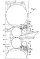
- FIG. 2 of the drawing shows that the device assigned to the upper work roll 55 ′ and the lower work roll 55 ′′ are basically constructed and arranged in the same way.
- the adjustment of the grinding units 59 and 60 or of the grinding unit pairs in the direction of the roller axis takes place via a feed drive 61 which is located together with the pair of grinding units on a cross member 62.
- This cross member 62 is in turn fastened to the guide rings 63 which are rotatably mounted concentrically to the support roller axis in the roller stands or the support roller chocks guided therein.
- control shafts 65 with the support roller and / or work roll chocks are at least vertically displaceable relative to the roll stands and furthermore in their distance from the work roll axes to a predetermined output diameter of the roll bales 55 'and 55 "of the work rolls 52' and 52 "can be tuned.
Abstract
Description
Die Erfindung betrifft ein Walzgerüst, insbesondere ein Vierwalzen-Walzgerüst zum Auswalzen von Bandmaterialquerschnitten unterschiedlicher Querschnittsbreiten, bei welchem die Walzreise mit der grössten vorkommenden Querschnittsbreite zu beginnen und mit der kleinsten vorkommenden Querschnittsbreite abzuschliessen ist und bei welchem die Stützlängen für die Ballen der Arbeitswalzen mindestens annähernd auf die jeweilige Querschnittsbreite der Bandmaterialquerschnitte einstellbar ist.The invention relates to a roll stand, in particular a four-roll roll stand for rolling out strip material cross sections of different cross-sectional widths, in which the rolling cycle has to begin with the largest cross-sectional width and must be completed with the smallest occurring cross-sectional width and in which the support lengths for the bales of the work rolls are at least approximately the same the respective cross-sectional width of the strip material cross-sections is adjustable.
Sowohl beim Warmwalzen als auch beim Kaltwalzen von Bandmaterial werden sehr hohe Anforderungen hinsichtlich der Erzielung eines optimalen Bandprofiles und einer hohen Ebenheit in Richtung der Walzgutbreite gestellt.Both hot rolling and cold rolling of strip material place very high demands on achieving an optimal strip profile and high flatness in the direction of the rolling stock width.
Beim Auswalzen von Bandmaterial mittels herkömmlicher Walzgerüste wird jedoch das Entstehen eines optimalen Bandprofiles beeinträchtigt, weil die durch Stützwalzen und ggf. auch Zwischenwalzen an einer Durchbiegung gehinderten Arbeitswalzen über die jeweilige Breite des Bandmaterials stark gedrückt werden, während die über die Walzgutbreite hinausragenden Längenbereiche dieser Arbeitswalzen walzdruckfrei bleiben. In dem durch das Bandmaterial stark gedrückten Bereich flachen sich daher die Arbeitswalzen an ihren mit der Stützwalze und auch derZwischenwalze in Kontaktberührung stehenden Umfangsabschnitt ab, während deren Walzdruck-freibleibende Längenbereiche nicht abgeplattet werden, sondern ihren kreisförmigen Querschnitt behalten. Hierdurch werden die Arbeitswalzen zwangsläufig an ihren Enden gegen den Walzspalt hin abgebogen mit der Folge, dass die Längskanten des Bandmaterials besonders hohen Beanspruchungen unterliegen und daher stärker gestaucht werden.When rolling out strip material by means of conventional roll stands, however, the formation of an optimal strip profile is impaired because the work rolls prevented from deflection by supporting rolls and possibly also intermediate rolls are strongly pressed over the respective width of the strip material, while the length ranges of these work rolls projecting beyond the width of the rolling stock are free of rolling pressure stay. In the region which is strongly pressed by the strip material, the work rolls therefore flatten out on their peripheral section which is in contact with the backup roll and also the intermediate roll, while their length areas which are not subject to rolling pressure are not flattened out, but rather retain their circular cross section. As a result, the work rolls are inevitably bent at their ends towards the roll gap, with the result that the longitudinal edges of the strip material are subject to particularly high loads and are therefore compressed more.
Um die Ebenheit des Bandmaterials in Richtung der Walzgutbreite zu verbessern, also das Bandprofil zu optimieren, gehört es durch die DE-C-995131 und die DE-B-2206912 zum Stand der Technik, Walzgerüste zu verwenden, bei denen die Arbeitswalzen an Zwischenwalzen und diese wiederum an Stützwalzen anliegen und wobei die Zwischenwalzen an ihren Enden kegelig verjüngt ausgebildet sind.In order to improve the flatness of the strip material in the direction of the rolling stock width, that is to say to optimize the strip profile, DE-C-995131 and DE-B-2206912 make it part of the prior art to use roll stands in which the work rolls on intermediate rolls and these in turn rest on support rollers and the intermediate rollers are tapered at their ends.
Die Zwischenwalzen sind dabei einerseits so ausgeführt, dass die kegelige Verjüngung ihrer beiden Endabschnitte jeweils dort beginnt, wo die Längskanten des auszuwalzenden Bandmaterials an den Arbeitswalzen zu liegen kommen. Nachteilig ist hier, dass für unterschiedlich breites Bandmaterial verschiedene Zwischenwalzen erforderlich sind, die eine aufwendige Lagerhaltung und einen häufigen Lagerwechsel erforderlich machen.The intermediate rolls are designed on the one hand so that the tapered tapering of their two end sections begins where the longitudinal edges of the strip material to be rolled come to rest on the work rolls. The disadvantage here is that different intermediate rolls are required for strip material of different widths, which necessitate complex storage and frequent bearing changes.
Andererseits gehört es aber auch zum Stand der Technik, Zwischenwalzen zu verwenden, die jeweils nur an einem Ende kegelig verjüngte Abschnitte haben und wobei das Zwischenwalzenpaar so in das Walzgerüst eingebaut ist, dass ihre kegelig verjüngten Endabschnitte an verschiedenen Gerüstseiten liegen. Durch gegenläufige Axialverschiebung der Zwischenwalzen lassen sich diese dabei so einstellen, dass der Beginn ihrer kegeligen Verjüngung jeweils dort zu liegen kommt, wo zwischen den Arbeitswalzen eine Längskante des zu walzenden Bandmaterials läuft. Nachteilig bei dieser bekannten Bauart eines Walzgerüstes ist jedoch der relativ hohe technische Aufwand, welcher für die Axialverschiebung der Zwischenwalzen getrieben werden muss. Als nachteilig hat es sich hierbei ferner erwiesen, dass das Verschieben der Zwischenwalzen bezogen auf diese und die Stützwalze, zu einer asymmetrischen Anordnung bzw. ungleichen Länge der Biegearme an den Arbeitswalzen führt, die das Entstehen eines einwandfreien Bandprofiles beeinträchtigen können. Die für die Arbeitswalzenverschiebung notwendigen Einrichtungen vermindern zudem den Modul des Walzgerüstes, erhöhen den Walzenverschleiss und bedingen ausserdem eine Abweichung von der herkömmlichen Walztechnik.On the other hand, it is also part of the state of the art to use intermediate rolls which each have conically tapered sections at one end only, and the pair of intermediate rolls is built into the roll stand in such a way that their tapered end sections lie on different sides of the stand. By opposing axial displacement of the intermediate rolls, they can be adjusted so that the start of their tapered taper is always where a longitudinal edge of the strip material to be rolled runs between the work rolls. A disadvantage of this known type of roll stand is, however, the relatively high technical outlay which must be carried out for the axial displacement of the intermediate rolls. It has also proven to be disadvantageous here that the displacement of the intermediate rolls relative to these and the backup roll leads to an asymmetrical arrangement or unequal length of the bending arms on the work rolls, which can impair the formation of a perfect strip profile. The equipment necessary for the work roll shifting also reduces the module of the roll stand, increases the roll wear and also causes a deviation from the conventional rolling technology.
Zur Vermeidung dieser Nachteile läuft ein älterer, nicht zum Stand der Technik gehörender Entwicklungsvorschlag darauf hinaus, mit minimalem technischen Aufwand die Herstellung optimaler und/oder in Richtung der Walzgutbreite genau ebener Bandprofile zu erreichen. Hierzu ist vorgesehen, dass die Arbeitswalzenballen in ihren über die jeweilige Walzgutbreite hinausragenden Längenbereichen durch Abtragen am Ballenumfang - gegeneinander und auch gegen die ihnen benachbarten Stützwalzen bzw. Zwischenwalzen - freigestellt werden. Die über die jeweilige Walzgutbreite hinausragenden Längenbereiche der Arbeitswalzenballen werden zu diesem Zweck im Walzgerüst bearbeitet, und zwar entweder in der Endphase eines Walzvorgangs oder aber während einer sehr kurzfristigen Unterbrechung des Walzvorgangs, wenn von der grösseren auf die nächst kleinere zu walzende Bandbreite übergegangen wird.In order to avoid these disadvantages, an older development proposal which does not belong to the state of the art amounts to achieving the production of optimal strip profiles which are exactly flat and / or exactly flat in the direction of the rolling stock width with minimal technical effort. For this purpose, it is provided that the work roll bales are freed in their length ranges projecting beyond the respective rolling stock width by abrasion on the circumference of the bale - against each other and also against the backup rolls or intermediate rolls adjacent to them. For this purpose, the length ranges of the work roll bales protruding beyond the respective rolling stock width are processed in the rolling stand, either in the final phase of a rolling process or during a very short interruption of the rolling process when the larger to the next smaller strip is to be rolled.
Mit Freistellen ist dabei eine durch Abdrehen, Abfräsen oder Abschleifen bewirkte Bearbeitung gemeint, die bei unbelasteten Walzen eine Durchmesserverminderung der Arbeitswalzenballen zwischen 0,1 bis 1,8 mm, vorzugsweise zwischen 0,2 und 1 mm, zur Folge hat.In this case, free-standing means a machining effected by turning, milling or grinding, which results in a diameter reduction of the work roll bale between 0.1 and 1.8 mm, preferably between 0.2 and 1 mm, in the case of unloaded rolls.
Der Erfindung ist nun das Ziel gesetzt, ein Walzgerüst der gattungsgemässen Art zu schaffen, in dem die Abtragsbearbeitung an den über die jeweilige Querschnittsbreite der auszuwalzenden Bandmaterialquerschnitte hinausragenden Längenbereichen der Arbeitswalzenballen schnell und zügig sowie mit höchster Genauigkeiterreichbar ist.The object of the invention is now to provide a roll stand of the generic type in which the removal machining can be carried out quickly and quickly and with the greatest accuracy at the length regions of the work roll bales which extend beyond the respective cross-sectional width of the strip material sections to be rolled out.
Die Lösung dieser Aufgabe wird nach der Erfindung im wesentlichen durch die im Kennzeichnungsteil des Anspruchs 1 angegebenen Merkmale erreicht.This object is achieved according to the invention essentially by the features specified in the characterizing part of claim 1.
Besonders vorteilhafte Weiterbildungsmerkmale für ein solches Walzgerüst sind erfindungsgemäss in den Ansprüchen 2 bis 4 aufgezeigt.Particularly advantageous further training features for such a rolling stand are shown according to the invention in claims 2 to 4.
Weitere Merkmale und Vorteile der Erfindung werden nachfolgend anhand eines in der Zeichnung dargestellten Ausführungsbeispieles näher erläutert. Hierbei zeigt:
- Fig. 1 in schematisch vereinfachter Prinzipdarstellung und in Walzrichtung gesehen den Walzensatz eines Vierwalzen-Walzgerüstes, wobei an den Arbeitswalzen die im Verlauf einer Walzreise an beiden Endabschnitten des Walzenballens vorzunehmenden Abtragung zur Freistellung des Ballenumfangs angedeutet sind, und
- Fig. 2 in grösserem Massstab und Seitenansicht das Vierwalzen-Walzgerüst nach Fig.1 mit den Arbeitswalzen als Abtragvorrichtungen zugeordneten Schleifaggregaten für die freistellende Bearbeitung des Ballenumfanges an den jeweils walzkraftfreien Ballen-Endabschnitten der Arbeitswalzen.
- Fig. 1 in a schematically simplified schematic representation and seen in the rolling direction, the roll set of a four-roll mill stand, with the removal of the bale circumference to be carried out on the work rolls in the course of a rolling trip to both end sections of the roll bale, and
- Fig. 2 in a larger scale and side view of the four-roll stand according to Fig.1 with the work rolls as removal devices assigned grinding units for the free processing of the bale circumference at the respective rolling force-free bale end sections of the work rolls.
Für die Auswalzung von Bandmaterialquerschnitten 51 mit in Richtung der Walzgutbreite genau ebenem Bandprofil muss mindestens ein Vierwalzen-Walzgerüst zum Einsatz gebracht werden, wie er in Fig. 1 schematisch dargestellt ist. Es hat einen aus zwei zusammenwirkenden Arbeitswalzen 52' und 52" bestehenden Arbeitswalzensatz 52 sowie einen aus zwei Stützwalzen 53' und 53" bestehenden Stützwalzensatz 53.For the rolling out of
Auch sogenannte Vielwalzen-Walzgerüste sind bereits für derartige Walzungen zum Einsatz gelangt, wobei diese so ausgelegt sind, dass die Arbeitswalzen 52' und 52" unter Zuordnung weiterer Zwischenwalzen mit den Stützwalzen 53' und 53" zusammenwirken.So-called multi-roll stands have already been used for such rolls, which are designed such that the work rolls 52 'and 52 "interact with the
Sowohl bei den Vierwalzen-Walzgerüsten nach Fig. 1 als auch bei den Vierwalzen-Walzgerüsten mit zusätzlichen Zwischenwalzen werden die an der Durchbiegung gehinderten Arbeitswalzen 52' und 52" über die jeweilige Querschnittsbreite 56 des auszuwalzenden Bandmaterialquerschnitts 51 stark gedrückt, wodurch sie sich in diesen Bereichen auf ihrem an der Stützwalze 53' bzw. 53" ober aber an der Zwischenwalze abstützenden Umfangsabschnitt abflachen. Hingegen sind die über die jeweilige Querschnittsbreite 56 hinausragenden Längenbereiche der Arbeitswalzen 52' und 52" walzdruckfrei, so dass sie nicht abgeplattet werden und damit ihren kreisförmigen Querschnitt behalten. Hierdurch bedingt werden jedoch die Arbeitswalzen 52' und 52" jeweils an ihren Enden gegen den Walzspalt 54 hin abgebogen.1 as well as the four-roll stands with additional intermediate rolls, the work rolls 52 'and 52 "which are prevented from bending are strongly pressed over the respective
Diesem eigentümlichen Verhalten der Arbeitswalzen 52' und 52" muss jedoch begegnet werden, wenn ein in Richtung der Querschnittsbreite 56 des Bandmaterialquerschnitts 51 genau ebenes Bandprofil erzielt und eine Kantenentschärfung, also die Bildung sogenannter edge drops an diesem unterbunden werden soll. Es muss daher eine Abstimmung der wirksamen Ballenbreite 57 der Arbeitswalzen 52' und 52" auf die jeweilige Querschnittsbreite 56 des Bandmaterialquerschnitts 51 herbeigeführt werden.This peculiar behavior of the work rolls 52 'and 52 "must, however, be countered if a strip profile that is exactly flat in the direction of the
Dabei ist davon auszugehen, dass jeder Arbeitswalzensatz 52 nach Beendigung der Walzreise gewechselt und die Walzenballen 55' und 55" der einzelnen Arbeitswalzen 52' und 52" durch einen mechanischen Abtragvorgang, beispielsweise durch Abdrehen, Abfräsen, Abschleifen oder auch andere geeignete Verfahren in ihrem Durchmesser, vorzugsweise zwischen 0,2 und 1,0 mm, verringert werden, bevor der betreffende Arbeitswalzensatz 52 für die nächste Walzreise wieder in das Walzgerüst eingebaut wird.It can be assumed that each
In Fig. 1 ist durch voll ausgezogene Linien der Arbeitswalzensatz 52 mit den beiden Arbeitswalzen 52' und 52" angedeutet, wie er bei einem Walzenwechsel in das Walzgerüsteingebautwird. Dabei sind die Walzenballen 55' und 55" der beiden Arbeitswalzen 52' und 52" für das Auswalzen eines Bandmaterialquerschnitts 51 mit einer grösstmöglichen Querschnittsbreite 56 ausgelegt. Da hierbei die Länge 57 der Walzenballen 55' und 55" an den Arbeitswalzen 52' und 52" annähernd gleich der grössten vorkommenden Querschnittsbreite 56 des Bandmaterialquerschnitts 51 ist, weisen die Walzenballen 55' und 55" praktisch keine walzdruckfreien Endbereiche auf, die ein Abbiegen der Walzenenden in Richtung gegen den Walzspalt 54 verursachen könnten.In Fig. 1, solid lines indicate the work roll set 52 with the two
Wird jedoch ein Bandmaterialquerschnitt 51 ausgewalzt, der eine geringere Querschnittsbreite 56 hat, wie das in Fig. 1 angedeutet ist, dann ragen die Walzenballen 55' und 55" mit ihrer maximalen Ballenlänge 57 beidendig um ein beträchtlich Mass über die Längskanten des Bandmaterialquerschnitts 51 hinaus.However, if a
Da diese über die Bandkanten hinausragenden Längenbereiche der Walzenballen 55' und 55" beim Auswalzen des in Fig. 1 dargestellten Bandmaterialquerschnitts 51 aber walzdruckfrei bleiben würden, könnten sie ein unerwünschtes Abbiegen der Walzenenden in den Walzspalt 54 hervorrufen und damit ein in Querrichtung unebenes Bandprofil des Bandmaterialquerschnitts 51 sowie auch unerwünschte Kantenentschärfung (edge drops) am Bandmaterialquerschnitt 51 hervorrufen.However, since these length regions of the
Zur Verhinderung dieser nachteiligen und höchst unerwünschten Folgen wird daher an den Walzenballen 55' und 55" beider Arbeitswalzen 52' und 52" des Arbeitswalzensatzes 52 während der Walzreise, d. h. bei im Walzgerüst verbleibendem Arbeitswalzensatz 52, beidendig ein mechanischer Abtragvorgang am Ballenumfang durchgeführt. Im vorliegenden Falle wird dieser Abtragvorgang durch Abschleifen so bewirkt, dass die über die jeweilige Querschnittsbreite 56 des Bandmaterialquerschnitts 51 hinausragenden Längenbereiche 58 der Walzenballen 55' und 55" im Durchmesser um ein Mass verringert werden, welches mindestens 0,1 und höchstens 1,8 mm beträgt, wie das in Fig. 1 - stark übertrieben - durch gestrichelte Linien angedeutet ist. Die wirksame Ballenlänge 57 wird dadurch auf ein der Querschnittsbreite 56 des Bandmaterialquerschnitts 51 angenähertes Mass gebracht, während gleichzeitig die Endbereiche der Walzenballen 55' und 55" beider Arbeitswalzen 52' und 52" des Arbeitswalzensatzes 52 jeweils auf dem Längenbereich 58 gegeneinander und auch gegen die Ballen der benachbarten Stützwalzen 53' und 53" des Stützwalzensatzes 53 freigestellt werden, wie das die gestrichelten Linien in Fig. 1 ebenfalls deutlich machen.To prevent these disadvantageous and highly undesirable consequences, therefore, on the
Solche Abtragvorgänge am Umfang der Walzenballen 55' und 55" beider Arbeitswalzen 52' und 52" des Arbeitswalzensatzes 52 wiederholt sich während jeder Walzreise mehrfach, d. h., sie werden in Abhängigkeit von der jeweiligen Querschnittsbreite 56 der in absteigender Folge auszuwalzenden, unterschiedlichen Bandmaterialbreiten aneinandergereiht.Such removal operations on the circumference of the
Da die Abtragsbearbeitung der Walzenballen 55' und 55" beider Arbeitswalzen 52' und 52" des Arbeitswalzensatzes 52 jeweils im Walzgerüst stattfindet, bevor die Auswalzung des nächsten Bandmaterialquerschnitts 51 kleinerer Querschnittsbreite beginnt, ist es wichtig, dass der Abtragvorgang mit möglichst geringem technischem Aufwand zügig und schnell sowie mit der für ein optimales Walzergebnis nötigen Präzision ausgeführt wird. Um das zu erreichen, ist dem Walzgerüst nach Fig. 1 für jede Arbeitswalze 52' und 52" des Arbeitswalzensatzes 52 eine Vorrichtung zugeordnet, die einen mechanischen Materialabtrag am Umfang der Walzenballen 55' und 55" jeweils im Bereich beider Ballenenden durch Abschleifen ermöglicht.Since the removal processing of the
Der Grundaufbau dieser Vorrichtung ist dabei aus Fig. 2 der Zeichnung ersichtlich, die erkennen lässt, dass die der oberen Arbeitswalze 55' und der unteren Arbeitswalze 55" zugeordneten Vorrichtung grundsätzlich gleichartig aufgebaut und angeordnet sind.The basic structure of this device can be seen from FIG. 2 of the drawing, which shows that the device assigned to the
Aus Fig. 2 ist ersichtlich, dass die zur Freistellung der walzdruckfreien Endbereiche der Walzenballen 55' und 55" durchzuführende Abtragsbearbeitung an beiden Arbeitswalzen 52' und 52" getrennt voneinander mittels Schleifaggregaten 59 und 60 stattfindet, die jeder Arbeitswalze 52 und 52' paarweise zugeordnet sind.From FIG. 2 it can be seen that the removal machining to be carried out on both
Die Verstellung der Schleifaggregate 59 und 60 bzw. der Schleifaggregat-Paare in Richtung der Walzenachse erfolgt dabei über einen Vorschubantrieb 61, der sich jeweils zusammen mit dem Schleifaggregat-Paar an einer Traverse 62 befindet. Diese Traverse 62 ist wiederum am konzentrisch zur Stützwalzenachse in den Walzenständern bzw. den darin geführten Stützwalzen-Einbaustücken drehbar gelagerten Führungsringen 63 befestigt. Durch Verdrehen der Führungsringe 63 mittels Stellzylinder 64 können dabei die als Schleifaggregat-Paare vorgesehenen Abtragvorrichtungen 59 bzw. 60 gegen den Umfang der Walzenballen 55' und 55" der Arbeitswalzen 52' und 52" um das jeweils notwendige Mass angestellt werden.The adjustment of the
Damit das jeweilige Ausmass der Abstellbewegung für die Abtragvorrichtungen 59 und 60, also die Eindringtiefe der beispielsweise von Schleifscheiben gebildeten Werkzeuge in den Umfang der Walzenballen 55' und 55" exakt bestimmt werden kann, sind im Walzgerüst besondere Steuerwellen 65 drehbar gelagert, die von aussen her, beispielsweise über Hebel 65', verstellt werden können und jeweils Exzenterscheiben 66 tragen, die als Anschläge für die Traverse 62 wirksam sind. Durch Veränderung der Drehlage für die Exzenter 66 kann also die Anschlagstellung für die Traverse 62 stufenlos verändert werden. Durch die Anschlagstellung lässt sich, wiederum in Abhängigkeit vom jeweiligen Durchmesser der Walzenballen 55' und 55" sowie auch vom jeweiligen Durchmesser der Schleifscheiben das Ausmass des Materialabtrags vom Umfang der Walzenballen 55' und 55" feinfühlig und sicher bestimmen. Wichtig ist dabei, dass den Exzenterscheiben 66 an den die Abtragvorrichtungen 59 and 60 haltenden und führenden Traversen 62 ebene Stützanschläge 66' zugeordnet sind.In order that the respective extent of the parking movement for the
Wichtig ist aber auch, dass die Steuerwellen 65 mit den Stützwalzen- und/oder Arbeitswalzen-Einbaustücken relativ zu den Walzenständern wenigstens höhenverlagerbar vorgesehen sind und ausserdem in ihrem Abstand von den Arbeitswalzenachsen auf einen vorgegebenen Ausgangsdurchmesser der Walzenballen 55' und 55"derArbeitswalzen 52' und 52" abgestimmt werden können.It is also important, however, that the
Claims (4)
Priority Applications (1)
| Application Number | Priority Date | Filing Date | Title |
|---|---|---|---|
| AT83107989T ATE16359T1 (en) | 1982-08-23 | 1983-08-12 | ROLLER FOR ROLLING STRIP MATERIAL OF DIFFERENT WIDTHS. |
Applications Claiming Priority (2)
| Application Number | Priority Date | Filing Date | Title |
|---|---|---|---|
| DE8223755U DE8223755U1 (en) | 1982-08-23 | 1982-08-23 | Roll stand for rolling out strip material of different widths |
| DE8223755U | 1982-08-23 |
Publications (2)
| Publication Number | Publication Date |
|---|---|
| EP0102014A1 EP0102014A1 (en) | 1984-03-07 |
| EP0102014B1 true EP0102014B1 (en) | 1985-11-06 |
Family
ID=6742993
Family Applications (1)
| Application Number | Title | Priority Date | Filing Date |
|---|---|---|---|
| EP83107989A Expired EP0102014B1 (en) | 1982-08-23 | 1983-08-12 | Rolling mill stand for rolling off strip material with different widths |
Country Status (5)
| Country | Link |
|---|---|
| US (1) | US4548064A (en) |
| EP (1) | EP0102014B1 (en) |
| JP (1) | JPS5954408A (en) |
| AT (1) | ATE16359T1 (en) |
| DE (2) | DE8223755U1 (en) |
Families Citing this family (6)
| Publication number | Priority date | Publication date | Assignee | Title |
|---|---|---|---|---|
| DE3631146A1 (en) * | 1986-09-12 | 1988-03-24 | Kocks Technik | DEVICE FOR CUTTING WORK SURFACE MACHINING OF ROLLERS |
| ES2039510T3 (en) * | 1987-07-24 | 1993-10-01 | Daidotokushuko Kabushikikaisha | METHOD OF SEPARATING ROLLERS FROM A LAMINATION TRAIN AND ROLLER CUTTING DEVICE. |
| DE4105079A1 (en) * | 1990-03-26 | 1991-10-02 | Schloemann Siemag Ag | Grinding device for maintaining roll at predetermined contour - with grinding disc on support which allows radial and parallel movement with respect to work roll |
| DE4409300A1 (en) * | 1994-03-18 | 1995-09-21 | Schloemann Siemag Ag | Device for processing rolls during the rolling process |
| US5970771A (en) * | 1998-07-10 | 1999-10-26 | Danieli United | Continuous spiral motion system for rolling mills |
| DE102008009902A1 (en) * | 2008-02-19 | 2009-08-27 | Sms Demag Ag | Rolling device, in particular push roll stand |
Family Cites Families (8)
| Publication number | Priority date | Publication date | Assignee | Title |
|---|---|---|---|---|
| DE887787C (en) * | 1941-06-13 | 1953-08-27 | Schloemann Ag | Polishing device for the rolls of rolling mills |
| US2566679A (en) * | 1943-02-25 | 1951-09-04 | Armzen Company | Rolling mill and lubrication method and means therefor |
| DE1037804B (en) * | 1954-10-01 | 1958-08-28 | E H Oskar Waldrich Dr Ing | Device on roller frames for reworking the rollers in the installed state |
| US3603125A (en) * | 1969-05-20 | 1971-09-07 | Reynolds Metals Co | Automatic control system for means for removing roll coating from a rolling mill work roll without removing the roll from the mill |
| GB1351074A (en) * | 1971-02-15 | 1974-04-24 | Hitachi Ltd | Rolling mills |
| DE2150781A1 (en) * | 1971-10-12 | 1973-04-19 | Schloemann Ag | ADJUSTMENT DEVICE FOR A ROTATING ROLLER BRUSH |
| JPS5633106A (en) * | 1979-08-28 | 1981-04-03 | Ishikawajima Harima Heavy Ind Co Ltd | Rolling mill equipped with roll grinder |
| JPS57137011A (en) * | 1981-02-16 | 1982-08-24 | Nippon Kokan Kk <Nkk> | Processing method of mill roll |
-
1982
- 1982-08-23 DE DE8223755U patent/DE8223755U1/en not_active Expired
-
1983
- 1983-08-12 DE DE8383107989T patent/DE3361178D1/en not_active Expired
- 1983-08-12 AT AT83107989T patent/ATE16359T1/en not_active IP Right Cessation
- 1983-08-12 EP EP83107989A patent/EP0102014B1/en not_active Expired
- 1983-08-19 US US06/524,833 patent/US4548064A/en not_active Expired - Fee Related
- 1983-08-19 JP JP58150442A patent/JPS5954408A/en active Pending
Also Published As
| Publication number | Publication date |
|---|---|
| EP0102014A1 (en) | 1984-03-07 |
| DE3361178D1 (en) | 1985-12-12 |
| US4548064A (en) | 1985-10-22 |
| ATE16359T1 (en) | 1985-11-15 |
| DE8223755U1 (en) | 1982-11-18 |
| JPS5954408A (en) | 1984-03-29 |
Similar Documents
| Publication | Publication Date | Title |
|---|---|---|
| EP0235332B1 (en) | Rolling mill stand | |
| DE3600144A1 (en) | ARRANGEMENT FOR REMOVING TIN, FROM HOT ROLLED STEEL TAPES | |
| EP0910486A1 (en) | Method and modular-multistation device for folding profiles | |
| DE3609290A1 (en) | BEARING ROLLER | |
| DE102010010758A1 (en) | Centerless cylindrical grinding machine for grinding bar-shaped workpieces and method for centerless cylindrical grinding of bar-shaped workpieces | |
| EP0620058B1 (en) | Straightening machine for wire | |
| DE3132815C2 (en) | Device for straightening steel pipes and the like | |
| EP0102014B1 (en) | Rolling mill stand for rolling off strip material with different widths | |
| EP0602492B1 (en) | Cluster mill | |
| EP0255714B1 (en) | Multiple-roll rolling mill stand with shiftable intermediary rolls having tapered ends | |
| EP0689884B1 (en) | Roller straightening machine for the straightening of profiles | |
| EP0665067A1 (en) | Cluster mill of the roll housing type preferably with direct hydraulic adjustment | |
| EP0086934B1 (en) | Method and roll stand for rolling strip of different width | |
| EP0103667B1 (en) | Double roller guide for rolling mills | |
| DE2528850C3 (en) | Pilgrim step mill for pipe cold rolling | |
| DE2623825B2 (en) | Rib rolling mill for processing tobacco stems | |
| EP0429815B1 (en) | Device for forming of a flange or similar, in particular at the end of a thin walled metalpipe | |
| DE10328052B4 (en) | Forming tool, in particular kneading tool | |
| DE1752361B2 (en) | ROLLING MILL FOR ROLLING BOX-SHAPED WORKPIECES | |
| DE3406313A1 (en) | ROLLING MILLS | |
| DE3844162C2 (en) | ||
| DE966802C (en) | Plant for the direct rolling of metal bars produced in the continuous casting process | |
| DE3206556A1 (en) | Method and roll stand for rolling out strip material of different widths | |
| DE19710060C2 (en) | Device for straightening cylindrical workpieces | |
| EP0204878B1 (en) | Cross-rolling mill |
Legal Events
| Date | Code | Title | Description |
|---|---|---|---|
| PUAI | Public reference made under article 153(3) epc to a published international application that has entered the european phase |
Free format text: ORIGINAL CODE: 0009012 |
|
| 17P | Request for examination filed |
Effective date: 19830819 |
|
| AK | Designated contracting states |
Designated state(s): AT BE DE FR GB IT |
|
| ITF | It: translation for a ep patent filed |
Owner name: STUDIO JAUMANN |
|
| GRAA | (expected) grant |
Free format text: ORIGINAL CODE: 0009210 |
|
| AK | Designated contracting states |
Designated state(s): AT BE DE FR GB IT |
|
| REF | Corresponds to: |
Ref document number: 16359 Country of ref document: AT Date of ref document: 19851115 Kind code of ref document: T |
|
| REF | Corresponds to: |
Ref document number: 3361178 Country of ref document: DE Date of ref document: 19851212 |
|
| ET | Fr: translation filed | ||
| PGFP | Annual fee paid to national office [announced via postgrant information from national office to epo] |
Ref country code: AT Payment date: 19860812 Year of fee payment: 4 |
|
| PLBE | No opposition filed within time limit |
Free format text: ORIGINAL CODE: 0009261 |
|
| STAA | Information on the status of an ep patent application or granted ep patent |
Free format text: STATUS: NO OPPOSITION FILED WITHIN TIME LIMIT |
|
| 26N | No opposition filed | ||
| PG25 | Lapsed in a contracting state [announced via postgrant information from national office to epo] |
Ref country code: AT Effective date: 19870812 |
|
| BERE | Be: lapsed |
Owner name: SMS SCHLOEMANN-SIEMAG A.G. Effective date: 19870831 |
|
| PG25 | Lapsed in a contracting state [announced via postgrant information from national office to epo] |
Ref country code: FR Free format text: LAPSE BECAUSE OF NON-PAYMENT OF DUE FEES Effective date: 19880429 |
|
| PG25 | Lapsed in a contracting state [announced via postgrant information from national office to epo] |
Ref country code: DE Effective date: 19880503 |
|
| GBPC | Gb: european patent ceased through non-payment of renewal fee | ||
| REG | Reference to a national code |
Ref country code: FR Ref legal event code: ST |
|
| PG25 | Lapsed in a contracting state [announced via postgrant information from national office to epo] |
Ref country code: GB Free format text: LAPSE BECAUSE OF NON-PAYMENT OF DUE FEES Effective date: 19881122 |
|
| PG25 | Lapsed in a contracting state [announced via postgrant information from national office to epo] |
Ref country code: BE Effective date: 19890831 |