EP0384924A1 - A process for producing a resin product having a bent hollow portion and a core usable for the same process - Google Patents
A process for producing a resin product having a bent hollow portion and a core usable for the same process Download PDFInfo
- Publication number
- EP0384924A1 EP0384924A1 EP89103519A EP89103519A EP0384924A1 EP 0384924 A1 EP0384924 A1 EP 0384924A1 EP 89103519 A EP89103519 A EP 89103519A EP 89103519 A EP89103519 A EP 89103519A EP 0384924 A1 EP0384924 A1 EP 0384924A1
- Authority
- EP
- European Patent Office
- Prior art keywords
- core
- resin
- hollow portion
- resin product
- producing
- Prior art date
- Legal status (The legal status is an assumption and is not a legal conclusion. Google has not performed a legal analysis and makes no representation as to the accuracy of the status listed.)
- Granted
Links
- 229920005989 resin Polymers 0.000 title claims abstract description 119
- 239000011347 resin Substances 0.000 title claims abstract description 119
- 238000000034 method Methods 0.000 title claims abstract description 54
- 238000000465 moulding Methods 0.000 claims description 41
- 229910052751 metal Inorganic materials 0.000 claims description 36
- 239000002184 metal Substances 0.000 claims description 36
- 229920001971 elastomer Polymers 0.000 claims description 35
- 239000000806 elastomer Substances 0.000 claims description 33
- 229910000743 fusible alloy Inorganic materials 0.000 claims description 27
- 230000014759 maintenance of location Effects 0.000 claims description 22
- 238000001746 injection moulding Methods 0.000 claims description 18
- 238000002844 melting Methods 0.000 claims description 11
- 230000008018 melting Effects 0.000 claims description 10
- 238000005304 joining Methods 0.000 claims description 3
- 239000011162 core material Substances 0.000 description 190
- 239000011248 coating agent Substances 0.000 description 14
- 238000000576 coating method Methods 0.000 description 14
- 238000001816 cooling Methods 0.000 description 12
- 238000004519 manufacturing process Methods 0.000 description 11
- 238000012856 packing Methods 0.000 description 11
- 229920002379 silicone rubber Polymers 0.000 description 10
- 239000004945 silicone rubber Substances 0.000 description 10
- 238000005266 casting Methods 0.000 description 9
- 238000010438 heat treatment Methods 0.000 description 8
- 229920001296 polysiloxane Polymers 0.000 description 7
- 239000000126 substance Substances 0.000 description 7
- 229920002302 Nylon 6,6 Polymers 0.000 description 6
- 230000000052 comparative effect Effects 0.000 description 6
- 238000005452 bending Methods 0.000 description 5
- 238000002347 injection Methods 0.000 description 4
- 239000007924 injection Substances 0.000 description 4
- 239000000463 material Substances 0.000 description 4
- 229910001120 nichrome Inorganic materials 0.000 description 4
- 229920006065 Leona® Polymers 0.000 description 3
- 239000000853 adhesive Substances 0.000 description 3
- 230000001070 adhesive effect Effects 0.000 description 3
- 229910045601 alloy Inorganic materials 0.000 description 3
- 239000000956 alloy Substances 0.000 description 3
- -1 and the like Polymers 0.000 description 3
- 230000006698 induction Effects 0.000 description 3
- 229910000838 Al alloy Inorganic materials 0.000 description 2
- RYGMFSIKBFXOCR-UHFFFAOYSA-N Copper Chemical compound [Cu] RYGMFSIKBFXOCR-UHFFFAOYSA-N 0.000 description 2
- 229910000881 Cu alloy Inorganic materials 0.000 description 2
- 229930182556 Polyacetal Natural products 0.000 description 2
- 239000003086 colorant Substances 0.000 description 2
- 238000000748 compression moulding Methods 0.000 description 2
- 229910052802 copper Inorganic materials 0.000 description 2
- 239000010949 copper Substances 0.000 description 2
- 230000005611 electricity Effects 0.000 description 2
- 229920001973 fluoroelastomer Polymers 0.000 description 2
- 239000006260 foam Substances 0.000 description 2
- 238000010097 foam moulding Methods 0.000 description 2
- 239000003921 oil Substances 0.000 description 2
- 239000004417 polycarbonate Substances 0.000 description 2
- 229920000139 polyethylene terephthalate Polymers 0.000 description 2
- 239000005020 polyethylene terephthalate Substances 0.000 description 2
- 229920006324 polyoxymethylene Polymers 0.000 description 2
- 239000005060 rubber Substances 0.000 description 2
- 238000007789 sealing Methods 0.000 description 2
- 229920005992 thermoplastic resin Polymers 0.000 description 2
- 238000003466 welding Methods 0.000 description 2
- 239000004604 Blowing Agent Substances 0.000 description 1
- 244000043261 Hevea brasiliensis Species 0.000 description 1
- 239000005062 Polybutadiene Substances 0.000 description 1
- XUIMIQQOPSSXEZ-UHFFFAOYSA-N Silicon Chemical compound [Si] XUIMIQQOPSSXEZ-UHFFFAOYSA-N 0.000 description 1
- 229910000831 Steel Inorganic materials 0.000 description 1
- 229920006362 Teflon® Polymers 0.000 description 1
- 229920006311 Urethane elastomer Polymers 0.000 description 1
- 229910052782 aluminium Inorganic materials 0.000 description 1
- XAGFODPZIPBFFR-UHFFFAOYSA-N aluminium Chemical compound [Al] XAGFODPZIPBFFR-UHFFFAOYSA-N 0.000 description 1
- 229910052787 antimony Inorganic materials 0.000 description 1
- 239000000919 ceramic Substances 0.000 description 1
- 230000006835 compression Effects 0.000 description 1
- 238000007906 compression Methods 0.000 description 1
- 235000019628 coolness Nutrition 0.000 description 1
- 230000001419 dependent effect Effects 0.000 description 1
- 230000008021 deposition Effects 0.000 description 1
- 230000006866 deterioration Effects 0.000 description 1
- 238000010586 diagram Methods 0.000 description 1
- OEBRKCOSUFCWJD-UHFFFAOYSA-N dichlorvos Chemical compound COP(=O)(OC)OC=C(Cl)Cl OEBRKCOSUFCWJD-UHFFFAOYSA-N 0.000 description 1
- 238000002845 discoloration Methods 0.000 description 1
- 230000000694 effects Effects 0.000 description 1
- 239000000945 filler Substances 0.000 description 1
- 239000004088 foaming agent Substances 0.000 description 1
- 239000003365 glass fiber Substances 0.000 description 1
- 238000003780 insertion Methods 0.000 description 1
- 230000037431 insertion Effects 0.000 description 1
- 239000011159 matrix material Substances 0.000 description 1
- 239000007769 metal material Substances 0.000 description 1
- 150000002739 metals Chemical class 0.000 description 1
- 239000000203 mixture Substances 0.000 description 1
- 229920003052 natural elastomer Polymers 0.000 description 1
- 229920001194 natural rubber Polymers 0.000 description 1
- 239000013307 optical fiber Substances 0.000 description 1
- 229920002857 polybutadiene Polymers 0.000 description 1
- 229920000515 polycarbonate Polymers 0.000 description 1
- 238000012545 processing Methods 0.000 description 1
- 230000001681 protective effect Effects 0.000 description 1
- 238000011084 recovery Methods 0.000 description 1
- 239000012744 reinforcing agent Substances 0.000 description 1
- 230000003014 reinforcing effect Effects 0.000 description 1
- 230000000717 retained effect Effects 0.000 description 1
- 229910052710 silicon Inorganic materials 0.000 description 1
- 239000010703 silicon Substances 0.000 description 1
- 238000007711 solidification Methods 0.000 description 1
- 230000008023 solidification Effects 0.000 description 1
- 239000003381 stabilizer Substances 0.000 description 1
- 239000010959 steel Substances 0.000 description 1
- 229920003051 synthetic elastomer Polymers 0.000 description 1
- 239000005061 synthetic rubber Substances 0.000 description 1
- 229920002725 thermoplastic elastomer Polymers 0.000 description 1
- 229920001187 thermosetting polymer Polymers 0.000 description 1
- 229910052718 tin Inorganic materials 0.000 description 1
- 238000012546 transfer Methods 0.000 description 1
- 238000001721 transfer moulding Methods 0.000 description 1
- XLYOFNOQVPJJNP-UHFFFAOYSA-N water Substances O XLYOFNOQVPJJNP-UHFFFAOYSA-N 0.000 description 1
- 229910052725 zinc Inorganic materials 0.000 description 1
Images







Classifications
-
- F—MECHANICAL ENGINEERING; LIGHTING; HEATING; WEAPONS; BLASTING
- F02—COMBUSTION ENGINES; HOT-GAS OR COMBUSTION-PRODUCT ENGINE PLANTS
- F02M—SUPPLYING COMBUSTION ENGINES IN GENERAL WITH COMBUSTIBLE MIXTURES OR CONSTITUENTS THEREOF
- F02M35/00—Combustion-air cleaners, air intakes, intake silencers, or induction systems specially adapted for, or arranged on, internal-combustion engines
- F02M35/10—Air intakes; Induction systems
- F02M35/10314—Materials for intake systems
- F02M35/10321—Plastics; Composites; Rubbers
-
- B—PERFORMING OPERATIONS; TRANSPORTING
- B29—WORKING OF PLASTICS; WORKING OF SUBSTANCES IN A PLASTIC STATE IN GENERAL
- B29C—SHAPING OR JOINING OF PLASTICS; SHAPING OF MATERIAL IN A PLASTIC STATE, NOT OTHERWISE PROVIDED FOR; AFTER-TREATMENT OF THE SHAPED PRODUCTS, e.g. REPAIRING
- B29C33/00—Moulds or cores; Details thereof or accessories therefor
- B29C33/44—Moulds or cores; Details thereof or accessories therefor with means for, or specially constructed to facilitate, the removal of articles, e.g. of undercut articles
- B29C33/48—Moulds or cores; Details thereof or accessories therefor with means for, or specially constructed to facilitate, the removal of articles, e.g. of undercut articles with means for collapsing or disassembling
- B29C33/50—Moulds or cores; Details thereof or accessories therefor with means for, or specially constructed to facilitate, the removal of articles, e.g. of undercut articles with means for collapsing or disassembling elastic or flexible
- B29C33/505—Moulds or cores; Details thereof or accessories therefor with means for, or specially constructed to facilitate, the removal of articles, e.g. of undercut articles with means for collapsing or disassembling elastic or flexible cores or mandrels, e.g. inflatable
-
- B—PERFORMING OPERATIONS; TRANSPORTING
- B29—WORKING OF PLASTICS; WORKING OF SUBSTANCES IN A PLASTIC STATE IN GENERAL
- B29C—SHAPING OR JOINING OF PLASTICS; SHAPING OF MATERIAL IN A PLASTIC STATE, NOT OTHERWISE PROVIDED FOR; AFTER-TREATMENT OF THE SHAPED PRODUCTS, e.g. REPAIRING
- B29C33/00—Moulds or cores; Details thereof or accessories therefor
- B29C33/44—Moulds or cores; Details thereof or accessories therefor with means for, or specially constructed to facilitate, the removal of articles, e.g. of undercut articles
- B29C33/52—Moulds or cores; Details thereof or accessories therefor with means for, or specially constructed to facilitate, the removal of articles, e.g. of undercut articles soluble or fusible
-
- B—PERFORMING OPERATIONS; TRANSPORTING
- B29—WORKING OF PLASTICS; WORKING OF SUBSTANCES IN A PLASTIC STATE IN GENERAL
- B29C—SHAPING OR JOINING OF PLASTICS; SHAPING OF MATERIAL IN A PLASTIC STATE, NOT OTHERWISE PROVIDED FOR; AFTER-TREATMENT OF THE SHAPED PRODUCTS, e.g. REPAIRING
- B29C53/00—Shaping by bending, folding, twisting, straightening or flattening; Apparatus therefor
- B29C53/02—Bending or folding
- B29C53/08—Bending or folding of tubes or other profiled members
- B29C53/083—Bending or folding of tubes or other profiled members bending longitudinally, i.e. modifying the curvature of the tube axis
-
- B—PERFORMING OPERATIONS; TRANSPORTING
- B29—WORKING OF PLASTICS; WORKING OF SUBSTANCES IN A PLASTIC STATE IN GENERAL
- B29D—PRODUCING PARTICULAR ARTICLES FROM PLASTICS OR FROM SUBSTANCES IN A PLASTIC STATE
- B29D23/00—Producing tubular articles
- B29D23/001—Pipes; Pipe joints
- B29D23/003—Pipe joints, e.g. straight joints
- B29D23/006—Elbows
-
- F—MECHANICAL ENGINEERING; LIGHTING; HEATING; WEAPONS; BLASTING
- F02—COMBUSTION ENGINES; HOT-GAS OR COMBUSTION-PRODUCT ENGINE PLANTS
- F02M—SUPPLYING COMBUSTION ENGINES IN GENERAL WITH COMBUSTIBLE MIXTURES OR CONSTITUENTS THEREOF
- F02M35/00—Combustion-air cleaners, air intakes, intake silencers, or induction systems specially adapted for, or arranged on, internal-combustion engines
- F02M35/10—Air intakes; Induction systems
- F02M35/10091—Air intakes; Induction systems characterised by details of intake ducts: shapes; connections; arrangements
- F02M35/10137—Flexible ducts, e.g. bellows or hoses
-
- F—MECHANICAL ENGINEERING; LIGHTING; HEATING; WEAPONS; BLASTING
- F02—COMBUSTION ENGINES; HOT-GAS OR COMBUSTION-PRODUCT ENGINE PLANTS
- F02M—SUPPLYING COMBUSTION ENGINES IN GENERAL WITH COMBUSTIBLE MIXTURES OR CONSTITUENTS THEREOF
- F02M35/00—Combustion-air cleaners, air intakes, intake silencers, or induction systems specially adapted for, or arranged on, internal-combustion engines
- F02M35/10—Air intakes; Induction systems
- F02M35/1034—Manufacturing and assembling intake systems
- F02M35/10347—Moulding, casting or the like
-
- F—MECHANICAL ENGINEERING; LIGHTING; HEATING; WEAPONS; BLASTING
- F02—COMBUSTION ENGINES; HOT-GAS OR COMBUSTION-PRODUCT ENGINE PLANTS
- F02M—SUPPLYING COMBUSTION ENGINES IN GENERAL WITH COMBUSTIBLE MIXTURES OR CONSTITUENTS THEREOF
- F02M35/00—Combustion-air cleaners, air intakes, intake silencers, or induction systems specially adapted for, or arranged on, internal-combustion engines
- F02M35/10—Air intakes; Induction systems
- F02M35/104—Intake manifolds
- F02M35/112—Intake manifolds for engines with cylinders all in one line
-
- B—PERFORMING OPERATIONS; TRANSPORTING
- B29—WORKING OF PLASTICS; WORKING OF SUBSTANCES IN A PLASTIC STATE IN GENERAL
- B29L—INDEXING SCHEME ASSOCIATED WITH SUBCLASS B29C, RELATING TO PARTICULAR ARTICLES
- B29L2023/00—Tubular articles
- B29L2023/22—Tubes or pipes, i.e. rigid
-
- F—MECHANICAL ENGINEERING; LIGHTING; HEATING; WEAPONS; BLASTING
- F02—COMBUSTION ENGINES; HOT-GAS OR COMBUSTION-PRODUCT ENGINE PLANTS
- F02M—SUPPLYING COMBUSTION ENGINES IN GENERAL WITH COMBUSTIBLE MIXTURES OR CONSTITUENTS THEREOF
- F02M35/00—Combustion-air cleaners, air intakes, intake silencers, or induction systems specially adapted for, or arranged on, internal-combustion engines
- F02M35/10—Air intakes; Induction systems
- F02M35/10091—Air intakes; Induction systems characterised by details of intake ducts: shapes; connections; arrangements
- F02M35/10131—Ducts situated in more than one plane; Ducts of one plane crossing ducts of another plane
-
- F—MECHANICAL ENGINEERING; LIGHTING; HEATING; WEAPONS; BLASTING
- F05—INDEXING SCHEMES RELATING TO ENGINES OR PUMPS IN VARIOUS SUBCLASSES OF CLASSES F01-F04
- F05C—INDEXING SCHEME RELATING TO MATERIALS, MATERIAL PROPERTIES OR MATERIAL CHARACTERISTICS FOR MACHINES, ENGINES OR PUMPS OTHER THAN NON-POSITIVE-DISPLACEMENT MACHINES OR ENGINES
- F05C2225/00—Synthetic polymers, e.g. plastics; Rubber
- F05C2225/08—Thermoplastics
Definitions
- This invention relates to a process for producing a resin product having a bent hollow portion, and a core used in said production process.
- Specific examples of applications of the process and the core include application to production processes of parts for automobiles which have a bent hollow portion, for instance, water inlet/outlet, pipes such as oil strainers, ducts of induction systems, and intake manifolds, in the case where metallic materials for these parts are replaced by resins.
- a low-melting alloy for example, melting point of 138°C
- the removal of the core consisting of the low-melting alloy by melting requires a long-time heating procedure for it to melt, and moreover in the case of mass production, recovery and re-casting of the melted low-melting alloy is indispensable.
- the above process is disadvantageous in that the productivity is very low and that heat deterioration of the resin tends to occur because of an indispensable long-time heating step at a rather high temperature which is not desirable for a resin product.
- the present invention relates to a process for producing a resin product having a bent hollow portion which is characterized by using a core having a high flexibility, a high retention of shape, and a surface coated with an elastomer.
- the present invention is characterized in that it permits easy production of the aforesaid product by a simple step of drawing out the core from a molded product, and the core being reusable.
- the first aspect of the invention is directed to a process for producing a resin product having a bent hollow portion.
- the second aspect is directed to a core used in said production process.
- the present invention is widely applicable also in the case where the resin product having a bent hollow portion is a two-forked product or a multi-forked pipe.
- a two-forked or multi-forked pipe having a complicated shape can easily be produced by using a combination of a plurality of cores and if necessary, an insert mandrel (hereinafter sometimes referred to as a die) or a part for branching.
- a process for producing a resin product having a bent hollow portion which is characterized by deforming a core obtained by coating a heat-resistant elastomer on a skeletal structure having high flexibility and shape retention into a desired shape, inserting the deformed core into a mold, packing a resin into the mold cavity, and then drawing out the core from the resulting molded product; and the core used in said production process.
- the second embodiment there are mentioned a process for producing a resin product having a bent hollow portion according to the first embodiment, in which there is used a core obtained by sealing a low-melting alloy in a skeletal structure having a high flexibility, to impart a high retention of shape to the skeletal structure; and the core used in this production process.
- a process for producing a resin product having a bent hollow portion in which there is used a core constructed by coating an elastomer on a skeletal structure having high flexibility and shape retention capability which has previously been deformed into a desired shape so as to have the same outer diameter in every portion of the core, thereby a precisely molded product can be obtained; and the core used in this production process.
- a core for multi-forked pipe is formed by properly choosing and combining the cores used in the above embodiments in consideration of their using positions, shapes, etc. If necessary, a rigid insert die and/or a part for branching are used for connection.
- a process for producing a hollow multi-forked pipe made of a resin which is characterized by connecting a plurality of the cores having high flexibility and shape retention used in the above embodiments to one another by means of a part for branching to obtain a core for molding, deforming the core into a desired shape, inserting the core into a mold, packing a resin into the mold cavity, and then drawing out the plurality of the cores from the resulting molded product.
- a process for producing a multi-forked resin pipe comprising a plurality of bent hollow portions and a hollow spacious portion communicating with the bent hollow portion, which is characterized by connecting a plurality of the cores used in the above embodiments which have high flexibility and shape retention to a rigid insert mandrel for forming the hollow spacious portion communicating with the bent hollow portion, deforming the plurality of the cores for forming bent pipe portions, into desired shapes to obtain a core for molding, inserting this core into a mold, packing a resin into the mold cavity, and then drawing out from the resulting molded product the plurality of the cores having high flexibility and shape retention and the rigid insert mandrel which constitute said core for molding.
- the above embodiments are applicable to foam molding, and in this case, there is provided a process for producing a resin product having a bent hollow portion according to the above various embodiments, in which the resin is obtained by foam molding.
- the present invention relates to a process for producing a resin product having a bent hollow portion, such as an S-tube or U-tube. More particularly, it relates to a process for producing a resin product having a bent hollow portion which comprises a step of molding a resin product by applying a resin at least around a core having such a high retention of shape that the core does not undergo substantial deformation by a resin flow during molding, and such a high flexibility that at the time of drawing out the core, the core is deformed in accordance with the shape of a molded product and hence does not injure the molded resin product, while keeping the core in a desired shape; and a step of drawing out the core.
- the passage "applying a resin at least around the core” means that the present invention is applied to a portion to form a molded product portion having a bent hollow portion in the case of production of a resin product having the molded product portion and a molded product portion having no bent hollow portion.
- a resin may be applied by a method suitable for molding a desired resin product, such as coating.
- the above-mentioned core of this invention has high flexibility and shape retention and comprises a skeletal structure, desirably hollow structure having a high flexibility, an elastomer covering the surface of said structure, and a means having a high retention of shape which is, if necessary, provided in the hollow portion of said structure.
- the core having high flexibility and shape retention used in this invention is preferably a core which has such a high flexibility that its bending or unbending force is such that the core can be deformed with a force not larger than the compression strength of resin matrix of product, and such a high retention of shape that the core is not deformed at least by the flow pressure (2 to 3 kg/cm2) of resin. More preferably, at the time of drawing out the core, the core has such a flexibility that its bending or unbending force is 50 kg or less, and the surface of core is coated with an elastomer which is not adhesive to a resin to be used, does not flow at the molding and processing temperature of said resin, and is heat-resistant, so as to avoid the uneveness of the surface.
- the skeletal structure constituting the aforesaid core having a high flexibility and such a high retention of shape that the core is not deformed by the flow pressure of resin is a structure having a high flexibility and for example, a cylindrical shape.
- Specific examples of the skeletal structure include, for example, ductile metal structures made of copper, copper alloy, lead, aluminum, aluminum alloy, or the like; flexible pipes such as bellows tubes obtained by forming a pipe from a thin plate of steel, copper, copper alloy, aluminum alloy, or the like, as skeletal structures having the structure shown in Fig. 1; and combinations of said ductile structures and said flexible pipes.
- the flexible pipes include, for instance, flexible pipes having the same constitution as those used in protective pipes for optical fibers, oscillating parts of desk or floor lamps, etc.
- the retention of shape can be improved by sealing a low-melting alloy in the hollow portion of a flexible pipe or a hose, for reinforcing the retention of shape, heating the pipe or hose to melt the low-melting metal, thereby imparting thereto flexibility, forming the pipe or hose into a desired shape, and then cooling the pipe or hose.
- the shape of the skeletal structure is usually a cylindrical shape, its section may be oval or square, according to the shape of a desired product.
- a method for the heating there can be employed various methods, for example, methods using an external apparatus, such as heating by heat transfer by means of hot air, and radio frequency induction heating, and a method of providing a heater inside the core.
- the constitution of the skeletal structure and a material constituting said structure are not critical, so long as said structure has a high flexibility and if necessary, a high retention of shape.
- the elastomer provided on the surface of the skeletal structure shown in Fig. 1 or Fig. 2 is not critical so long as it abolishes the uneveness of surface of the skeletal structure, has such a heat resistance that it does not flow at a molding temperature for a resin to be molded, and is not adhesive to said resin.
- Specific examples of elastomers usable in this invention include natural rubber, synthetic rubbers such as silicone rubber, fluororubber, urethane rubber, butadiene rubber, and the like, and thermoplastic elastomers.
- molding methods such as casting under vacuum, injection, compression molding, and the like.
- a straight metal rod which fits the inside diameter of the skeletal structure is inserted into the skeletal structure and fixed for positioning of skeletal structure in a mold, after which the skeletal structure is inserted into a mold for coating with rubber, and the elastomer is provided thereon by casting under vacuum, or the like.
- the elastomer can be provided in a desired shape from the beginning by inserting a metal rod previously bent into a desired shape into the skeletal structure, fixing the metal rod, thereafter inserting the skeletal structure into a mold for coating with rubber, and coating the skeletal structure with the elastomer.
- the radius of curvature is less than 80 mm in the bent portion of a resin to be produced by using a core constructed of a flexible pipe and an elastomer (e.g., a heat shrinkable silicone tube)
- a core constructed of a flexible pipe and an elastomer (e.g., a heat shrinkable silicone tube)
- firstly said pipe is covered by an elastomer tube, and, then an elastomer coating is provided on said elastomer tube, thereby the flexibility of the core can be retained because only small portions of the tube can enter the depressions of the flexible tube and the depressions are prevented from being filled by the elastomer coating.
- the two elastomers are preferably highly adhesive to each other and more preferably of the same kind.
- the thickness of the elastomer provided is not critical, so long as the uneveness of surface of the skeletal structure is abolished.
- a specific process for producing the core is as follows.
- the process for producing the core which is the second aspect of the invention is described below in detail with reference to Figs. 3 to 10.
- a metal terminal part 1 having portions for positioning and supporting in a mold by means of pins or the like during molding and a gripe or a hitching portion, and a metal terminal part 2 are attached to the skeletal structure 3 (a flexible pipe) shown in Fig. 1 or Fig. 2 at one end of a flexible pipe and the other end, respectively, by a means such as welding, or bolts and nuts.
- a metal rod 6 which fits the inside diameter of the skeletal structure having the metal terminal parts 1 and 2 attached thereto is inserted into the skeletal structure and fixed by means of, for example, bolts.
- the surface of the skeletal structure 3 is covered with a heat-shrinkable tube made of silicone (thickness: 0.5 to 1 mm) 4 and the tube is heated to be adhered to the surface of the skeletal structure 3.
- a heat-shrinkable tube made of silicone (thickness: 0.5 to 1 mm) 4 and the tube is heated to be adhered to the surface of the skeletal structure 3.
- said structure is inserted into a cylindrical mold 8 for vacuum casting, and the mold cavity is evacuated by means of a vacuum pump 9.
- silicone rubber 5 of the same kind as with the tube 4 covering said structure is injected so as to make its surface smoothly and adjust its size to the inside diameter of a product, followed by pressurizing.
- said structure is coated with the silicone rubber 5, which is then heated and vulcanized.
- an adapter 7 may be used in the coating with the silicone rubber 5.
- the adapter may be used for positioning in the mold 8.
- a flexible heater 10 which, like the skeletal structure, has a high flexibility is inserted into the hollow portion of said structure and fixed.
- a low-melting alloy 11 is sealed in a space between the inner surface of the skeletal structure 3 and the outer surface of the flexible heater 10, whereby the desired core is obtained.
- the melting point of alloy to be sealed therein will be in range of about 50°C as a lower limit and about 140°C as an upper limit, while the alloy can be freely chosen depending upon a kind of the resin, the manner for applying the resin and the like.
- the metal terminal part 2 should have such a shape as causes no trouble in withdrawal of the core from a molded product.
- the skeletal structure 3 one which has the constitution shown in Fig. 1 is used, it can sufficiently exhibit a function as the core in this invention even when neither flexible heater 10 nor low-melting alloy 11 are inserted into the hollow portion of said structure.
- the aforesaid heater having a high flexibility has a capacity enough to generate a heat capacity sufficient for melting the low-melting alloy 11 sealed in the core.
- the heater is as follows. Specific examples of the constitution of the heater are explained below with reference to Fig. 8.
- skeletal structure 18 of the heater there is used one which has the same constitution as that of the skeletal structure used in the aforesaid core.
- the metal terminal parts 1 and 2 shown in Figs. 3 and 4 and metal terminals 12 and 13 for fixation are attached to said structure by welding.
- the surface of said structure is covered with an insulating layer 14 (a heat-shrinkable silicone tube and the like), after which a glass-Nichrome wire 15 is wound on to said structure at adequate intervals of, for example, about 5 mm.
- the wire 16 for electric source a Teflon® (a registered trademark of Du Pont) coated wire having a high heat resistance is preferably used in view of the surface temperature of the glass-Nichrome wire.
- the surface of the thus treated skeletal structure is coated with an elastomer 17 (silicone rubber) which, at least, does not flow at the melting point of the low-melting alloy to be used, whereby a flexible heater is completed.
- elastomer 17 silicone rubber
- the hollow portion of a small flexible pipe 18 of the heater can be used as a cooling cavity for cooling the core to solidify the low-melting alloy inside the core.
- a glass-Nichrome wire 15 may be wound on to the core itself in the same manner as described above.
- a skeletal structure 19 having the same constitution as that of the aforesaid skeletal structure is inserted into the central portion of the core and fixed, and the hollow portion of an inner flexible pipe 19 is used as a cooling cavity for reducing the amount of the low-melting alloy 11, whereby the solidification time can be reduced.
- the skeletal structure 19, requires a treatment, for example, coating of its surface with an elastomer for preventing air leakage.
- materials constituting said heater and the constitution of said heater are not critical so long as they satisfy the requirements according to the present invention.
- a metal terminal part 21 should, of course, be designed by considering the curvature radius of a metal rod 20 previously bent into a desired shape so that as shown in Fig. 10, the metal rod can be inserted into the skeletal structure 3 and drawn out therefrom.
- a split mold should be used.
- thermoplastic resins or thermosetting resins may be used so long as they satisfy required characteristics of the resin product.
- the resin may be incorporated with desired amounts of reinforcing agents, fillers, foaming agents, coloring agents, stabilizing agents, coloring agents, etc.
- thermoplastic resin used as the resin used for producing a resin product having a bent hollow portion by means of the core of this invention comprising a skeletal structure having high flexibility and shape retention and an elastomer coating thereon
- methods such as injection molding, foam injection molding, and the like.
- thermosetting resin there can be used molding methods such as injection molding cast molding, transfer molding, compression molding, and the like.
- the cores 100 of the above third embodiment are used. Two of the cores are preformed in the same manner as described above, and then connected to each other by means of a part for branching 101 having a snap-fit structure for uniting the two cores in a body, to obtain a core for molding. Next, the core for molding thus obtained is inserted into a mold 8B and positioned.
- the part-for-branching 101 portion may be fixed by forming a projection or the like on the part for branching 101, and a hole in the mold 8B at the same position as that of the projection.
- a resin 5B is packed into the mold 8B by injection molding or the like, after which the core 100 is drawn out from the resulting molded product while fixing the flange portion, by the same method as used in the case of the above S-tube, whereby a resin product of two-forked tube shape is obtained.
- the part for branching is left in the molded product and constitute a part of the product.
- magnets 103 are provided in a mold insert mandrel 104 for forming a hollow spacious portion which leads out of bent pipe portions, as in the case of the adapter shown in Fig. 12.
- a plurality of the cores 100 which have previously been preformed are connected to one another by means of the magnets 103 to obtain a core for molding.
- the core for molding is inserted into a mold 8C, and a resin 5 is packed into the mold cavity by injection molding or the like.
- the resulting molded product 106 is taken out and the mold insert die 104 is drawn out, after which the core 100 is drawn out to obtain the resin product in the shape of a multi-forked pipe.
- a resin product having a bent hollow portion can be obtained by deforming a core having high flexibility and shape retention into a desired shape, inserting the deformed core into a mold, packing a resin into the mold cavity, and then drawing out the core from the resulting molded product.
- a plurality of the cores of this invention are united in a body by means of a part for branching or the like and used as a core for molding.
- constitution of a core for producing a two-forked molded product is the constitution of a core produced by combining the cores of this invention with a part for branching (a core-connecting part).
- part for branching means a part obtained by combining, by fitting, parts previously molded integrally or in at least two pieces, and joining them to one another by adhesion, deposition or the like.
- the structure of the part for branching and a material therefor are not critical so long as the part for branching has an ability to hold a plurality of the cores by insertion, interposition, or the like.
- the material there can used, for example, resins, metals, and ceramics.
- a core for a multi-forked pipe having a complicated shape When a core for a multi-forked pipe having a complicated shape is formed, it is sufficient that a plurality of the cores of this invention are connected to a rigid mold inset die, a core, or the like to unit them in a body.
- the core thus obtained can be used as a core for molding.
- the cores of the first and second embodiments are pushed in a mold for preforming while bending, and preformed.
- a mold for preforming 55 and an adapter 54 having pin holes or the like for positioning in a mold for injection molding, casting or the like are connected to the metal terminal part 2 side of a core 53.
- a method for the connection of the adapter 54 to said core there may be employed either a method of fixation by means of bolts, etc. or a method of inlaying a magnet 56 or the like in the adapter 54 and attaching the core to the adapter by means of the magnetic force.
- the preformed core having the adapter 54 attached thereto is insert into the pin projections of a mold 8A while retaining its shape, and positioned, after which a resin 5A is packed into the cavity portion of the mold 8A by injection molding or the like.
- a resin 5A is packed into the cavity portion of the mold 8A by injection molding or the like.
- the core 53 in the resulting molded product is drawn out directly from the molded product in the mold. It is also possible to take out the core together with the molded product from the mold, fix the flange portion of the molded product 5B on a fixing instrument 59, and draw out 53 the core from the molded product 58, for example, by seizing or highing the metal terminal part 1 or the core by means of a seizing tool 60 or the like, or by using oil pressure. In this case, the adapter used for positioning in the mold is separated from the core 53 and left at the end of the molded product 5B or in the mold 8A.
- the core drawn out and the adapter 54 separated from the core are again combined and then preformed by means of a mold for preforming, and molding is carried out in the same manner as described above.
- the heater inside the core is first heated to melt the low-melting alloy inside the core, imparting a high flexibility to the core, and the core and an adapter 54 are pushed in at a predetermined position of a mold for preforming 8′ while bending the same.
- the low-melting alloy inside the core is solidified, for example, by natural cooling, cooling of the mold for preforming 8, or cooling by induction of air into the cooling cavity inside the core.
- the core is then inserted into a mold 8A, and a resin 5 is packed into the mold cavity by injection molding, casting, or the like.
- the heater inside the core is again heated to melt the low-melting alloy inside the core, and the core is drawn out in the same manner as described above, after which the procedure described above is repeated to obtain a molded product 51.
- the designs of the metal terminal part 1 having a portion to hitch, the adapter 54 and the hitching tool 60 used in the present invention are not critical so long as withdrawal of the core from a molded product and positioning of the core in a mold are possible.
- a core was produced as follows.
- a metal flexible tube (outside diameter ⁇ 19 mm, inside diameter ⁇ 16 mm) having the constitution shown in Fig. 1A was covered with a heat-shrinkable silicone tube (thickness 1 mm, inside diameter ⁇ 30 mm) and heated in an over at 150°C for 10 minutes to shrink the silicone tube, whereby the silicone tube was adhered to the surface of flexible pipe.
- silicone rubber was coated as elastomer on the flexible pipe to a thickness of 1.5 mm by casting under vacuum and vulcanized at about 150°C.
- the core thus obtained was deformed so as to fit the inside dimension of the S-tube and then inserted into a mold, after which the surface of core was coated with 33% GRF-reinforced nylon 66 (LEONA® 1300G mfd. by Asahi Chemical Industry Co.) by injection molding. After the molding, the core was drawn out from the molded product in the mold. The core could be drawn out with a force of about 100 kg, and thus a bent hollow pipe made of the resin could easily be obtained.
- Injection molding conditions Injection pressure (kg/cm2) primary/secondary 600/200 Packing time (sec) 3 Cooling time (sec) 40 Mold temperature (°C) 76 Resin temperature (°C) 280
- Example 2 The same metal flexible pipe as used in Example 1 was coated with a heat-shrinkable silicone tube and fluororubber as elastomers in the same manner as in Example 1 to obtain a core.
- the core was deformed, followed by molding. Then, the core was drawn out from the resulting molded product. The core could be drawn out with substantially the same drawing force as in Example 1. A bent hollow pipe made of the resin was thus obtained.
- polyacetal TENAC® GA520 mfd. by Asahi Chemical Industry Ltd., reinforced with 20% of glass fiber e.g., GF
- polyethylene terephthalate SUNPET® 3300G mfd. by Asahi Chemical Industry Ltd., reinforced with 30% of GF
- PPS Shin-etsu Chemical Industry Co., Ltd.
- polycarbonate NOVAREX® 7025G30 mfd. by Mitsubishi Chemical Industries Ltd., reinforced with 30% of GF
- a core was produced as follows.
- a flexible tube (outside diameter ⁇ 19 mm, inside diameter ⁇ 16mm) made of a metal (SUS) which had the constitution shown in Fig. 2A was coated with silicone rubber by the same method as in Example 1 so as to adjust the outside diameter of the coated tube to ⁇ 27 mm.
- a flexible heater as shown in Fig. 8 which had an outside diameter of ⁇ 14 mm and a heater capacity of 60 w/m was inserted into the flexible pipe coated with silicone rubber and fixed, and a low-melting alloy (melting point: 138°C) was powered between the heater and the flexible tube and shut up therein to obtain a core (Fig. 7).
- the heater inside the core was heated at 150°C to melt the low-melting alloy, after which the core was deformed in the same manner as in Example 1 and cooled to solidify the low-melting alloy, whereby the core was preformed.
- the core was then inserted into a mold and 33% GF-reinforced nylon 66 resin was packed into the mold cavity in the same manner as in Example 1.
- the heater was charged with electricity for about 3 minutes from the beginning of cooling time to melt the low-melting alloy inside the core again, and the core was drawn out from the molded product in the mold.
- the core could easily be drawn out with a force of about 70 kg, and a bent pipe made of the resin was thus obtained.
- Molding was conducted in exactly the same manner as in Example 4, except that the melting point of low-melting alloy inside the core used in Example 4 was changed from 138°C to 74°C (substantially the same temperature as the mold temperature).
- the center temperature of the core reached 100°C in cooling time (60 sec), and the low-melting alloy inside the core melted without charging the inner heater with electricity. Consequently, the core could be drawn out from the molded product, and a bent hollow pipe made of the resin was obtained.
- Example 5 Using the core used in Example 5, a composition prepared by incorporating 0.3% of a blowing agent into the resin (30% GF-reinforced nylon 66 resin) was subjected to structural form injection molding (foam level: 5 to 10%) by a short-shot method. The core was drawn out from the resulting molded product to obtain a bent hollow pipe made of the resin. In this case, the core could easily be drawn out with a drawing force 30% lower than that in Example 5.
- a blowing agent 30% GF-reinforced nylon 66 resin
- a metal rod which had previously been bent so as to fit a S-tube shape was inserted into the same flexible metal pipe as used in Example 4 which served as a skeletal structure.
- the metal pipe was then coated with a heat-shrinkable silicon tube and silicone rubber as elastomers by the same vacuum casting as in Example 1 except for using a split mold.
- the core thus obtained was inserted into a mold and 33% GF-reinforced nylon 66 resin was molded in exactly the same manner as in Example 1, after which the core was drawn out from the molded product.
- the core could be drawn out from the molded product with a force of about 100 kg, and thus a bent hollow pipe made of the resin could easily be obtained.
- FIG. 17 As shown in Fig. 17, four cores having the same constitution as that of the core used in Fig. 4 were connected to a mold insert die for forming a hollow spacious portion, by means of the magnetic power of magnet inlaid in the mode insert die, whereby a core for molding was obtained.
- the molding was conducted by the same method as in Example 4, after which the four cores were drawn out one by one. Thereafter, the metal insert die was drawn out to obtain a resin product having a bent hollow portion containing a hollow spacious portion.
- a core was cast in a low-melting alloy (melting point of 138°C) in the shape of the S-tube shown in Fig. 11 so as to adjust the inside diameter of hollow portion of the tube to ⁇ 27 mm.
- the core was inserted into a mold for injection molding and 33% GF-reinforced nylon 66 resin (LEONA® (300G) mfd. by Asahi Chemical Industry Co., of natural color) was packed into the mold cavity at an injection pressure of 500 kg/cm2.
- the molded product was taken out of the mold and placed in a heating chamber (an air oven) at 150°C to melt away the core. But, the melting-away of the core required 3 hours or more and a color change of the molded article occurred.
- the low-melting alloy adhered to the inner surface of the S-tube molded product and could not completely be removed in the case of the method employed herein.
- a flexible metal pie (outside diameter ⁇ 19 mm, inside diameter 16 mm) having the constitution shown in Fig.-1(a) was used as a core.
- the flexible pipe was deformed into a desired shape and then inserted into a mold, and injection molding was conducted in the same manner as in Comparative Example 1. After the molding, an attempt was made to draw out the core from the molded product, but because of intrusion of resin into the uneven portion of the flexible tube, the core could not be drawn out and was broken.
Landscapes
- Engineering & Computer Science (AREA)
- Mechanical Engineering (AREA)
- Chemical & Material Sciences (AREA)
- Combustion & Propulsion (AREA)
- General Engineering & Computer Science (AREA)
- Manufacturing & Machinery (AREA)
- Moulds For Moulding Plastics Or The Like (AREA)
- Injection Moulding Of Plastics Or The Like (AREA)
Abstract
Description
- This invention relates to a process for producing a resin product having a bent hollow portion, and a core used in said production process. Specific examples of applications of the process and the core include application to production processes of parts for automobiles which have a bent hollow portion, for instance, water inlet/outlet, pipes such as oil strainers, ducts of induction systems, and intake manifolds, in the case where metallic materials for these parts are replaced by resins.
- As a process for producing a resin product having a bent hollow portion, such as an S-tube or U-tube, which cannot easily be obtained by molding by means of, for example, a slide core, there is a process which comprises forming a low-melting alloy (for example, melting point of 138°C) consisting of Zn, Sn, Sb, etc. previously by casting, inserting the formed product into a mold as a core, coating the core with a resin, then heating the core consisting of the low-melting alloy to melt away the same from the resulting molded product, and thereby obtaining a resin product having a bent hollow portion.
- However, the removal of the core consisting of the low-melting alloy by melting requires a long-time heating procedure for it to melt, and moreover in the case of mass production, recovery and re-casting of the melted low-melting alloy is indispensable. Thus, the above process is disadvantageous in that the productivity is very low and that heat deterioration of the resin tends to occur because of an indispensable long-time heating step at a rather high temperature which is not desirable for a resin product.
- The present invention relates to a process for producing a resin product having a bent hollow portion which is characterized by using a core having a high flexibility, a high retention of shape, and a surface coated with an elastomer. The present invention is characterized in that it permits easy production of the aforesaid product by a simple step of drawing out the core from a molded product, and the core being reusable.
- That is, the first aspect of the invention is directed to a process for producing a resin product having a bent hollow portion. The second aspect is directed to a core used in said production process.
- Embodiments of the first and second aspects are described below.
- The present invention is widely applicable also in the case where the resin product having a bent hollow portion is a two-forked product or a multi-forked pipe. In this case, a two-forked or multi-forked pipe having a complicated shape can easily be produced by using a combination of a plurality of cores and if necessary, an insert mandrel (hereinafter sometimes referred to as a die) or a part for branching.
- As the first embodiment, there are mentioned a process for producing a resin product having a bent hollow portion which is characterized by deforming a core obtained by coating a heat-resistant elastomer on a skeletal structure having high flexibility and shape retention into a desired shape, inserting the deformed core into a mold, packing a resin into the mold cavity, and then drawing out the core from the resulting molded product; and the core used in said production process.
- As the second embodiment, there are mentioned a process for producing a resin product having a bent hollow portion according to the first embodiment, in which there is used a core obtained by sealing a low-melting alloy in a skeletal structure having a high flexibility, to impart a high retention of shape to the skeletal structure; and the core used in this production process.
- As a preferable embodiment of the first embodiment, there are mentioned a process for producing a resin product having a bent hollow portion according to the first embodiment, in which there is used a core constructed by coating an elastomer on a skeletal structure having high flexibility and shape retention capability which has previously been deformed into a desired shape so as to have the same outer diameter in every portion of the core, thereby a precisely molded product can be obtained; and the core used in this production process.
- When a multi-forked pipe is produced, a core for multi-forked pipe is formed by properly choosing and combining the cores used in the above embodiments in consideration of their using positions, shapes, etc. If necessary, a rigid insert die and/or a part for branching are used for connection.
- As embodiments under such conditions, the following are mentioned.
- First, there is mentioned a process for producing a hollow multi-forked pipe made of a resin which is characterized by connecting a plurality of the cores having high flexibility and shape retention used in the above embodiments to one another by means of a part for branching to obtain a core for molding, deforming the core into a desired shape, inserting the core into a mold, packing a resin into the mold cavity, and then drawing out the plurality of the cores from the resulting molded product.
- Second, there is mentioned a process for producing a multi-forked resin pipe comprising a plurality of bent hollow portions and a hollow spacious portion communicating with the bent hollow portion, which is characterized by connecting a plurality of the cores used in the above embodiments which have high flexibility and shape retention to a rigid insert mandrel for forming the hollow spacious portion communicating with the bent hollow portion, deforming the plurality of the cores for forming bent pipe portions, into desired shapes to obtain a core for molding, inserting this core into a mold, packing a resin into the mold cavity, and then drawing out from the resulting molded product the plurality of the cores having high flexibility and shape retention and the rigid insert mandrel which constitute said core for molding.
- In addition, the above embodiments are applicable to foam molding, and in this case, there is provided a process for producing a resin product having a bent hollow portion according to the above various embodiments, in which the resin is obtained by foam molding.
-
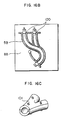
- Figs. 1 to 17 show examples of the cores of the present invention, their constitutions, and flow sheets of molding steps using the cores.
- Fig. 1A and Fig. 1B show examples of the constitution of a flexible metal pipe as core material which has high flexibility and shape retention. Fig. 2A and Fig. 2B show examples of the constitution of a flexible metal pipe having a high flexibility alone. A partially enlarged view is shown in the upper portion of each figure.
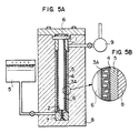
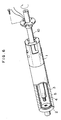
- Fig. 3 and Fig. 4 are examples of diagrams showing the constitution of a core. Fig. 5 is a cross-sectional view for showing a working state of an apparatus used for coating an elastomer on the surface of a flexible pipe having the constitution shown in Fig. 2A, in producing a core using the flexible tube.
- Fig. 6 and Fig. 7A show examples of core composed of a combination of the flexible pipe shown in Fig. 2, a low-melting alloy, and a flexible heater.
- Fig. 7B is a partially enlarged view of the constitution of core shown in Fig. 7A.
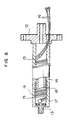
- Fig. 8 shows one example of the flexible heater constituting the aforesaid skeletal structure.
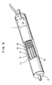
- Fig. 9 shows one example of variation of the constitution of core shown in Fig. 7.
- Fig. 10 shows one example of a connection state of a terminal metal part portion in the case where the aforesaid flexible pipe is coated in a bent state with an elastomer.
- Fig. 11 shows one example of flanged S-tube made of a resin of the present invention. Figs. 12 and 13 show parts for fixing a core in a mold, and accessory parts. In the Figures, 52, 54, 55 and 56 show a projection for combining the core itself with an adapter (54), the adapter, a mold for giving a shape, and a magnet for fixing or connecting the core itself with the adapter, respectively.
- Figs. 14A through Fig. 14D and Fig. 15 are schematic illustrations of examples of molding step in the case where the core of this invention is used, and method for drawing out the core. In Figs. 14A through Fig. 14D, 8′ shows a mold for giving a shape, 5A a resin, 8A a mold for injection molding, and 60 a pull for withdrawal. In Figs. 15A through Fig. 15D, 54A, 51, and 59 show an adapter, a molded product, and a clamp plate, respectively.
- Figs. 16 and 17 show a combination of a plurality of cores and a part for connecting the cores to each other, and a combination of cores with one another, in the case of production of a two-forked tube or a multi-forked tube.
- The present invention relates to a process for producing a resin product having a bent hollow portion, such as an S-tube or U-tube. More particularly, it relates to a process for producing a resin product having a bent hollow portion which comprises a step of molding a resin product by applying a resin at least around a core having such a high retention of shape that the core does not undergo substantial deformation by a resin flow during molding, and such a high flexibility that at the time of drawing out the core, the core is deformed in accordance with the shape of a molded product and hence does not injure the molded resin product, while keeping the core in a desired shape; and a step of drawing out the core.
- In this invention, the passage "applying a resin at least around the core" means that the present invention is applied to a portion to form a molded product portion having a bent hollow portion in the case of production of a resin product having the molded product portion and a molded product portion having no bent hollow portion. As to a method for the application, although injection molding or cast molding is usually employed, a resin may be applied by a method suitable for molding a desired resin product, such as coating.
- The above-mentioned core of this invention has high flexibility and shape retention and comprises a skeletal structure, desirably hollow structure having a high flexibility, an elastomer covering the surface of said structure, and a means having a high retention of shape which is, if necessary, provided in the hollow portion of said structure.
- The core having high flexibility and shape retention used in this invention is preferably a core which has such a high flexibility that its bending or unbending force is such that the core can be deformed with a force not larger than the compression strength of resin matrix of product, and such a high retention of shape that the core is not deformed at least by the flow pressure (2 to 3 kg/cm²) of resin. More preferably, at the time of drawing out the core, the core has such a flexibility that its bending or unbending force is 50 kg or less, and the surface of core is coated with an elastomer which is not adhesive to a resin to be used, does not flow at the molding and processing temperature of said resin, and is heat-resistant, so as to avoid the uneveness of the surface.
- The skeletal structure constituting the aforesaid core having a high flexibility and such a high retention of shape that the core is not deformed by the flow pressure of resin is a structure having a high flexibility and for example, a cylindrical shape. Specific examples of the skeletal structure include, for example, ductile metal structures made of copper, copper alloy, lead, aluminum, aluminum alloy, or the like; flexible pipes such as bellows tubes obtained by forming a pipe from a thin plate of steel, copper, copper alloy, aluminum alloy, or the like, as skeletal structures having the structure shown in Fig. 1; and combinations of said ductile structures and said flexible pipes. Examples of the flexible pipes include, for instance, flexible pipes having the same constitution as those used in protective pipes for optical fibers, oscillating parts of desk or floor lamps, etc. In order to keep in a desired shape a skeletal structure having the constitution shown in Fig. 2, the retention of shape can be improved by sealing a low-melting alloy in the hollow portion of a flexible pipe or a hose, for reinforcing the retention of shape, heating the pipe or hose to melt the low-melting metal, thereby imparting thereto flexibility, forming the pipe or hose into a desired shape, and then cooling the pipe or hose. Although the shape of the skeletal structure is usually a cylindrical shape, its section may be oval or square, according to the shape of a desired product.
- In this case, as a method for the heating, there can be employed various methods, for example, methods using an external apparatus, such as heating by heat transfer by means of hot air, and radio frequency induction heating, and a method of providing a heater inside the core.
- However, in this invention, the constitution of the skeletal structure and a material constituting said structure are not critical, so long as said structure has a high flexibility and if necessary, a high retention of shape.
- The elastomer provided on the surface of the skeletal structure shown in Fig. 1 or Fig. 2 is not critical so long as it abolishes the uneveness of surface of the skeletal structure, has such a heat resistance that it does not flow at a molding temperature for a resin to be molded, and is not adhesive to said resin. Specific examples of elastomers usable in this invention include natural rubber, synthetic rubbers such as silicone rubber, fluororubber, urethane rubber, butadiene rubber, and the like, and thermoplastic elastomers.
- As a method for providing the elastomer on the skeletal structure shown in Fig. 1 or Fig. 2, there can be employed molding methods such as casting under vacuum, injection, compression molding, and the like.
- Specifically, a straight metal rod which fits the inside diameter of the skeletal structure is inserted into the skeletal structure and fixed for positioning of skeletal structure in a mold, after which the skeletal structure is inserted into a mold for coating with rubber, and the elastomer is provided thereon by casting under vacuum, or the like.
- The elastomer can be provided in a desired shape from the beginning by inserting a metal rod previously bent into a desired shape into the skeletal structure, fixing the metal rod, thereafter inserting the skeletal structure into a mold for coating with rubber, and coating the skeletal structure with the elastomer.
- However, when the radius of curvature is less than 80 mm in the bent portion of a resin to be produced by using a core constructed of a flexible pipe and an elastomer (e.g., a heat shrinkable silicone tube), firstly said pipe is covered by an elastomer tube, and, then an elastomer coating is provided on said elastomer tube, thereby the flexibility of the core can be retained because only small portions of the tube can enter the depressions of the flexible tube and the depressions are prevented from being filled by the elastomer coating. The two elastomers are preferably highly adhesive to each other and more preferably of the same kind.
- The thickness of the elastomer provided is not critical, so long as the uneveness of surface of the skeletal structure is abolished.
- A specific process for producing the core is as follows. The process for producing the core which is the second aspect of the invention is described below in detail with reference to Figs. 3 to 10.
- As shown in Figs. 3 and 4, a metal terminal part 1 having portions for positioning and supporting in a mold by means of pins or the like during molding and a gripe or a hitching portion, and a
metal terminal part 2 are attached to the skeletal structure 3 (a flexible pipe) shown in Fig. 1 or Fig. 2 at one end of a flexible pipe and the other end, respectively, by a means such as welding, or bolts and nuts. Next, ametal rod 6 which fits the inside diameter of the skeletal structure having themetal terminal parts 1 and 2 attached thereto is inserted into the skeletal structure and fixed by means of, for example, bolts. The surface of theskeletal structure 3 is covered with a heat-shrinkable tube made of silicone (thickness: 0.5 to 1 mm) 4 and the tube is heated to be adhered to the surface of theskeletal structure 3. Subsequently, as shown in Fig. 5, said structure is inserted into acylindrical mold 8 for vacuum casting, and the mold cavity is evacuated by means of avacuum pump 9. Then,silicone rubber 5 of the same kind as with thetube 4 covering said structure is injected so as to make its surface smoothly and adjust its size to the inside diameter of a product, followed by pressurizing. Thus, said structure is coated with thesilicone rubber 5, which is then heated and vulcanized. In this case, if necessary, an adapter 7 may be used in the coating with thesilicone rubber 5. In the present process, the adapter may be used for positioning in themold 8. - Next, the metal rod inserted into the
skeletal structure 3 coated with the silicone rubber is drawn out from said structure. As shown in Figs. 6 and 7, aflexible heater 10 which, like the skeletal structure, has a high flexibility is inserted into the hollow portion of said structure and fixed. Then, a low-meltingalloy 11 is sealed in a space between the inner surface of theskeletal structure 3 and the outer surface of theflexible heater 10, whereby the desired core is obtained. The melting point of alloy to be sealed therein will be in range of about 50°C as a lower limit and about 140°C as an upper limit, while the alloy can be freely chosen depending upon a kind of the resin, the manner for applying the resin and the like. - Needless to say, the
metal terminal part 2 should have such a shape as causes no trouble in withdrawal of the core from a molded product. When as theskeletal structure 3, one which has the constitution shown in Fig. 1 is used, it can sufficiently exhibit a function as the core in this invention even when neitherflexible heater 10 nor low-meltingalloy 11 are inserted into the hollow portion of said structure. - It is sufficient that the aforesaid heater having a high flexibility has a capacity enough to generate a heat capacity sufficient for melting the low-melting
alloy 11 sealed in the core. Specifically, the heater is as follows. Specific examples of the constitution of the heater are explained below with reference to Fig. 8. - As
skeletal structure 18 of the heater, there is used one which has the same constitution as that of the skeletal structure used in the aforesaid core. Themetal terminal parts 1 and 2 shown in Figs. 3 and 4 andmetal terminals Nichrome wire 15 is wound on to said structure at adequate intervals of, for example, about 5 mm. In this case, when lead-outwires 16 for electric source are desired to be in the same direction, the glass-Nichrome wire 15 andwires 16 for electric source are wound on to the insulatinglayer 14 in parallel with each other. As thewire 16 for electric source, a Teflon® (a registered trademark of Du Pont) coated wire having a high heat resistance is preferably used in view of the surface temperature of the glass-Nichrome wire. - Finally, the surface of the thus treated skeletal structure is coated with an elastomer 17 (silicone rubber) which, at least, does not flow at the melting point of the low-melting alloy to be used, whereby a flexible heater is completed.
- The hollow portion of a small
flexible pipe 18 of the heater can be used as a cooling cavity for cooling the core to solidify the low-melting alloy inside the core. - It is sufficient that the provision of said elastomer is carried out in the same manner as for the provision on the surface of the skeletal structure of core shown in Fig. 5.
- Needless to say, as shown in Fig. 9, a glass-
Nichrome wire 15 may be wound on to the core itself in the same manner as described above. Preferably, askeletal structure 19 having the same constitution as that of the aforesaid skeletal structure is inserted into the central portion of the core and fixed, and the hollow portion of an innerflexible pipe 19 is used as a cooling cavity for reducing the amount of the low-meltingalloy 11, whereby the solidification time can be reduced. Theskeletal structure 19, of course, requires a treatment, for example, coating of its surface with an elastomer for preventing air leakage. - Needless to say, materials constituting said heater and the constitution of said heater are not critical so long as they satisfy the requirements according to the present invention.
- When an elastomer is previously coated in a desired shape in the case of a heater having the same constitution as in the above specific example, a
metal terminal part 21 should, of course, be designed by considering the curvature radius of ametal rod 20 previously bent into a desired shape so that as shown in Fig. 10, the metal rod can be inserted into theskeletal structure 3 and drawn out therefrom. In this case, a split mold should be used. - As the resin used in the process for producing a molded product having bent hollow portion of this invention, either thermoplastic resins or thermosetting resins may be used so long as they satisfy required characteristics of the resin product. The resin may be incorporated with desired amounts of reinforcing agents, fillers, foaming agents, coloring agents, stabilizing agents, coloring agents, etc.
- When a thermoplastic resin is used as the resin used for producing a resin product having a bent hollow portion by means of the core of this invention comprising a skeletal structure having high flexibility and shape retention and an elastomer coating thereon, there can be employed methods such as injection molding, foam injection molding, and the like. When a thermosetting resin is used, there can be used molding methods such as injection molding cast molding, transfer molding, compression molding, and the like.
- As a specific example, a process for producing a resin product in the form of two-forked pipe or multi-forked pipe is explained below with reference to Figs. 16 and 17. First, one example of production of a two-forked pipe is explained below.
- In the two-forked pipe having a bent hollow portion shown in Fig. 16, the
cores 100 of the above third embodiment are used. Two of the cores are preformed in the same manner as described above, and then connected to each other by means of a part for branching 101 having a snap-fit structure for uniting the two cores in a body, to obtain a core for molding. Next, the core for molding thus obtained is inserted into amold 8B and positioned. In this case, when fixation only at the end of the core involves a problem (for example, movement of the part for branching due to flow pressure of resin at the time of packing a resin 5), the part-for-branching 101 portion may be fixed by forming a projection or the like on the part for branching 101, and a hole in themold 8B at the same position as that of the projection. - Subsequently, a
resin 5B is packed into themold 8B by injection molding or the like, after which thecore 100 is drawn out from the resulting molded product while fixing the flange portion, by the same method as used in the case of the above S-tube, whereby a resin product of two-forked tube shape is obtained. - In this case, the part for branching is left in the molded product and constitute a part of the product.
- Next, in the case of the resin product in the shape of a multi-forked pipe shown in Fig. 17,
magnets 103 are provided in amold insert mandrel 104 for forming a hollow spacious portion which leads out of bent pipe portions, as in the case of the adapter shown in Fig. 12. A plurality of thecores 100 which have previously been preformed are connected to one another by means of themagnets 103 to obtain a core for molding. Subsequently, the core for molding is inserted into amold 8C, and aresin 5 is packed into the mold cavity by injection molding or the like. Then, the resulting moldedproduct 106 is taken out and the mold insert die 104 is drawn out, after which thecore 100 is drawn out to obtain the resin product in the shape of a multi-forked pipe. - According to the present invention, a resin product having a bent hollow portion can be obtained by deforming a core having high flexibility and shape retention into a desired shape, inserting the deformed core into a mold, packing a resin into the mold cavity, and then drawing out the core from the resulting molded product.
- For producing a resin product of two-forked or multi-forked pipe shape, it is sufficient that a plurality of the cores of this invention are united in a body by means of a part for branching or the like and used as a core for molding.
- One example of constitution of a core for producing a two-forked molded product is the constitution of a core produced by combining the cores of this invention with a part for branching (a core-connecting part).
- Here, the term "part for branching" means a part obtained by combining, by fitting, parts previously molded integrally or in at least two pieces, and joining them to one another by adhesion, deposition or the like. The structure of the part for branching and a material therefor are not critical so long as the part for branching has an ability to hold a plurality of the cores by insertion, interposition, or the like. As the material, there can used, for example, resins, metals, and ceramics.
- When a core for a multi-forked pipe having a complicated shape is formed, it is sufficient that a plurality of the cores of this invention are connected to a rigid mold inset die, a core, or the like to unit them in a body. The core thus obtained can be used as a core for molding.
- Specific examples are explained below for a pipe in the shape of the flanged S-tube shown in Fig. 11 with reference to Figs. 12, 13, 14 and 15.
- For example, in the case of the cores of the first and second embodiments, the cores are pushed in a mold for preforming while bending, and preformed. In this case, a mold for preforming 55 and an
adapter 54 having pin holes or the like for positioning in a mold for injection molding, casting or the like are connected to themetal terminal part 2 side of acore 53. As a method for the connection of theadapter 54 to said core, there may be employed either a method of fixation by means of bolts, etc. or a method of inlaying amagnet 56 or the like in theadapter 54 and attaching the core to the adapter by means of the magnetic force. - Subsequently, the preformed core having the
adapter 54 attached thereto is insert into the pin projections of amold 8A while retaining its shape, and positioned, after which aresin 5A is packed into the cavity portion of themold 8A by injection molding or the like. In this case, it is preferable to pack theresin 5A into themold 8A from the metal terminal part 1 portion of the core so as to prevent generation of a bending force by the core 53 as much as possible. - After the packing of the resin into the
mold 8A, the core 53 in the resulting molded product is drawn out directly from the molded product in the mold. It is also possible to take out the core together with the molded product from the mold, fix the flange portion of the moldedproduct 5B on a fixinginstrument 59, and draw out 53 the core from the molded product 58, for example, by seizing or highing the metal terminal part 1 or the core by means of a seizingtool 60 or the like, or by using oil pressure. In this case, the adapter used for positioning in the mold is separated from thecore 53 and left at the end of the moldedproduct 5B or in themold 8A. - The core drawn out and the
adapter 54 separated from the core are again combined and then preformed by means of a mold for preforming, and molding is carried out in the same manner as described above. - In the case of the core of the third embodiment, the heater inside the core is first heated to melt the low-melting alloy inside the core, imparting a high flexibility to the core, and the core and an
adapter 54 are pushed in at a predetermined position of a mold for preforming 8′ while bending the same. Next, the low-melting alloy inside the core is solidified, for example, by natural cooling, cooling of the mold for preforming 8, or cooling by induction of air into the cooling cavity inside the core. The core is then inserted into amold 8A, and aresin 5 is packed into the mold cavity by injection molding, casting, or the like. - Subsequently, the heater inside the core is again heated to melt the low-melting alloy inside the core, and the core is drawn out in the same manner as described above, after which the procedure described above is repeated to obtain a molded
product 51. - The designs of the metal terminal part 1 having a portion to hitch, the
adapter 54 and the hitchingtool 60 used in the present invention are not critical so long as withdrawal of the core from a molded product and positioning of the core in a mold are possible. - This invention is illustrated with the following examples, which should not be construed as limiting the scope of the invention.
- For forming the hollow portion of the flanged S-tube (length: 200 m, outside diameter ø34 mm, curvature radius; 50 mm, outside diameter of the flange portion: ø60 mm) shown in Fig. 11, a core was produced as follows. A metal flexible tube (outside diameter ø19 mm, inside diameter ø16 mm) having the constitution shown in Fig. 1A was covered with a heat-shrinkable silicone tube (thickness 1 mm, inside diameter ø30 mm) and heated in an over at 150°C for 10 minutes to shrink the silicone tube, whereby the silicone tube was adhered to the surface of flexible pipe. Then, silicone rubber was coated as elastomer on the flexible pipe to a thickness of 1.5 mm by casting under vacuum and vulcanized at about 150°C.
- Next, the core thus obtained was deformed so as to fit the inside dimension of the S-tube and then inserted into a mold, after which the surface of core was coated with 33% GRF-reinforced nylon 66 (LEONA® 1300G mfd. by Asahi Chemical Industry Co.) by injection molding. After the molding, the core was drawn out from the molded product in the mold. The core could be drawn out with a force of about 100 kg, and thus a bent hollow pipe made of the resin could easily be obtained. These steps are schematically shown in Fig. 8.
Injection molding conditions Injection pressure (kg/cm²) primary/secondary 600/200 Packing time (sec) 3 Cooling time (sec) 40 Mold temperature (°C) 76 Resin temperature (°C) 280 - The same metal flexible pipe as used in Example 1 was coated with a heat-shrinkable silicone tube and fluororubber as elastomers in the same manner as in Example 1 to obtain a core. In the same manner as in Example 1, the core was deformed, followed by molding. Then, the core was drawn out from the resulting molded product. The core could be drawn out with substantially the same drawing force as in Example 1. A bent hollow pipe made of the resin was thus obtained.
- Using the cores used in Examples 1 and 2, four resins, polyacetal (TENAC® GA520 mfd. by Asahi Chemical Industry Ltd., reinforced with 20% of glass fiber e.g., GF), polyethylene terephthalate (SUNPET® 3300G mfd. by Asahi Chemical Industry Ltd., reinforced with 30% of GF), PPS (Shin-etsu Chemical Industry Co., Ltd.) and polycarbonate (NOVAREX® 7025G30 mfd. by Mitsubishi Chemical Industries Ltd., reinforced with 30% of GF) were individually injection-molded in the same manner as in Example 1. The cores were drawn out from the molded products. In the case of these cores, the force required for the withdrawal was not greatly dependent on the kind of resin, and bent hollow resin pipes could easily be obtained.
Injection molding conditions for resin Polyacetal PET PPS PC Injection pressure (kg/cm²) primary/secondary 650/200 700/200 700/200 850/200 Packing time (sec) 3 3 3 3 Cooling time (sec) 60 60 60 60 Mold temperature (°C) 76 100 80 90 Resin temperature (°C) 200 280 310 280 - A core was produced as follows. A flexible tube (outside diameter ø19 mm, inside diameter ø16mm) made of a metal (SUS) which had the constitution shown in Fig. 2A was coated with silicone rubber by the same method as in Example 1 so as to adjust the outside diameter of the coated tube to ø27 mm. Then, such a flexible heater as shown in Fig. 8 which had an outside diameter of ø14 mm and a heater capacity of 60 w/m was inserted into the flexible pipe coated with silicone rubber and fixed, and a low-melting alloy (melting point: 138°C) was powered between the heater and the flexible tube and shut up therein to obtain a core (Fig. 7).
- Subsequently, the heater inside the core was heated at 150°C to melt the low-melting alloy, after which the core was deformed in the same manner as in Example 1 and cooled to solidify the low-melting alloy, whereby the core was preformed. The core was then inserted into a mold and 33% GF-reinforced nylon 66 resin was packed into the mold cavity in the same manner as in Example 1. After the packing, the heater was charged with electricity for about 3 minutes from the beginning of cooling time to melt the low-melting alloy inside the core again, and the core was drawn out from the molded product in the mold. The core could easily be drawn out with a force of about 70 kg, and a bent pipe made of the resin was thus obtained.
- Molding was conducted in exactly the same manner as in Example 4, except that the melting point of low-melting alloy inside the core used in Example 4 was changed from 138°C to 74°C (substantially the same temperature as the mold temperature).
- After packing of the resin into the mold cavity was completed, the center temperature of the core reached 100°C in cooling time (60 sec), and the low-melting alloy inside the core melted without charging the inner heater with electricity. Consequently, the core could be drawn out from the molded product, and a bent hollow pipe made of the resin was obtained.
- Using the core used in Example 5, a composition prepared by incorporating 0.3% of a blowing agent into the resin (30% GF-reinforced nylon 66 resin) was subjected to structural form injection molding (foam level: 5 to 10%) by a short-shot method. The core was drawn out from the resulting molded product to obtain a bent hollow pipe made of the resin. In this case, the core could easily be drawn out with a drawing force 30% lower than that in Example 5.
- A metal rod which had previously been bent so as to fit a S-tube shape was inserted into the same flexible metal pipe as used in Example 4 which served as a skeletal structure. The metal pipe was then coated with a heat-shrinkable silicon tube and silicone rubber as elastomers by the same vacuum casting as in Example 1 except for using a split mold. The core thus obtained was inserted into a mold and 33% GF-reinforced nylon 66 resin was molded in exactly the same manner as in Example 1, after which the core was drawn out from the molded product. The core could be drawn out from the molded product with a force of about 100 kg, and thus a bent hollow pipe made of the resin could easily be obtained.
- As shown in Fig. 16, two cores having the same constitution as that of the core used in Example 7 were connected to each other by fitting by means of part of branching made of resin having a snap-fitting structure and projections enabling positioning in a mold which had previously been made of 43% GF-reinforced nylon 66 resin (LEONA® 14G43 mfd. by Asahi Chemical Industry Co.) by injection molding in two pieces. Then, the ends of the cores and the part for branching were fixed by interposition, as a core for molding, simultaneously with mold-closing operation, and molding was conducted by the same method as in Example 4. Thereafter, only the two cores were drawn out from the molded product to obtain a two-forked resin product having a bent hollow portion. In this case, the part for branching remained in the molded product and constituted a part of the product.
- As shown in Fig. 17, four cores having the same constitution as that of the core used in Fig. 4 were connected to a mold insert die for forming a hollow spacious portion, by means of the magnetic power of magnet inlaid in the mode insert die, whereby a core for molding was obtained.
- The molding was conducted by the same method as in Example 4, after which the four cores were drawn out one by one. Thereafter, the metal insert die was drawn out to obtain a resin product having a bent hollow portion containing a hollow spacious portion.
- In all of the above examples, there occurred neither marked change of the thickness of molded product nor its breakage at the time of withdrawal of the core, and a resin product having a satisfactory bent hollow portion could be obtained. Moreover, repeated use of the core had no substantial influence on the quality of molded product.
- A core was cast in a low-melting alloy (melting point of 138°C) in the shape of the S-tube shown in Fig. 11 so as to adjust the inside diameter of hollow portion of the tube to ø27 mm.
- Then, the core was inserted into a mold for injection molding and 33% GF-reinforced nylon 66 resin (LEONA® (300G) mfd. by Asahi Chemical Industry Co., of natural color) was packed into the mold cavity at an injection pressure of 500 kg/cm². After the molding, the molded product was taken out of the mold and placed in a heating chamber (an air oven) at 150°C to melt away the core. But, the melting-away of the core required 3 hours or more and a color change of the molded article occurred. In addition, the low-melting alloy adhered to the inner surface of the S-tube molded product and could not completely be removed in the case of the method employed herein.
- In order to reduce thermal discoloration of molded product and melting-away time molding was conducted using an alloy having a melting point of 74°C, in the same manner as in Comparative Example 1.
- But, the surface of the core melted at the resin temperature at the time of resin packing, so that no satisfactory molded product could be obtained.
- For forming the hollow portion of the flanged S-tube shown in Fig. 11, a flexible metal pie (outside diameter ø19 mm, inside
diameter 16 mm) having the constitution shown in Fig.-1(a) was used as a core. The flexible pipe was deformed into a desired shape and then inserted into a mold, and injection molding was conducted in the same manner as in Comparative Example 1. After the molding, an attempt was made to draw out the core from the molded product, but because of intrusion of resin into the uneven portion of the flexible tube, the core could not be drawn out and was broken. - As is clear from the above examples, the present invention has the following peculiar effects.
- (1) The core of this invention obtained by coating a skeletal structure having high flexibility and shape retention with an elastomer can be repeatedly used, and a resin product having a bent hollow portion can easily be obtained merely by drawing out the core after applying the core with a resin.
- (2) A resin product having a bent hollow portion composed of a two-forked or multi-forked pipe having a complicatedly forked, bent, hollow portion can easily be obtained by using a plurality of cores combined by means of a part for branching, or the like.
Claims (15)
a step of molding a resin product by keeping in a desired shape a core which has such a high retention of shape that the core is not substantially deformed by resin flow during molding, and such a high flexibility that at the time of withdrawal of the core, the core is deformed in accordance with the shape of molded product and does not injure the molded resin product, and applying a resin at least around the core, and
a step of withdrawing said core after the molding.
Priority Applications (4)
| Application Number | Priority Date | Filing Date | Title |
|---|---|---|---|
| EP89103519A EP0384924B1 (en) | 1989-02-28 | 1989-02-28 | A process for producing a resin product having a bent hollow portion and a core usable for the same process |
| DE68920424T DE68920424T2 (en) | 1989-02-28 | 1989-02-28 | A process for producing a resin article with a curved hollow part and core applicable in this process. |
| CA000592630A CA1332493C (en) | 1989-02-28 | 1989-03-02 | Process for producing a resin product having a bent hollow portion and a core usable for the same process |
| US07/535,295 US5176866A (en) | 1989-02-28 | 1990-06-08 | Process for producing a resin product having a bent hollow portion and a core usable for the same process |
Applications Claiming Priority (3)
| Application Number | Priority Date | Filing Date | Title |
|---|---|---|---|
| EP89103519A EP0384924B1 (en) | 1989-02-28 | 1989-02-28 | A process for producing a resin product having a bent hollow portion and a core usable for the same process |
| CA000592630A CA1332493C (en) | 1989-02-28 | 1989-03-02 | Process for producing a resin product having a bent hollow portion and a core usable for the same process |
| US07/535,295 US5176866A (en) | 1989-02-28 | 1990-06-08 | Process for producing a resin product having a bent hollow portion and a core usable for the same process |
Publications (2)
| Publication Number | Publication Date |
|---|---|
| EP0384924A1 true EP0384924A1 (en) | 1990-09-05 |
| EP0384924B1 EP0384924B1 (en) | 1995-01-04 |
Family
ID=27168229
Family Applications (1)
| Application Number | Title | Priority Date | Filing Date |
|---|---|---|---|
| EP89103519A Expired - Lifetime EP0384924B1 (en) | 1989-02-28 | 1989-02-28 | A process for producing a resin product having a bent hollow portion and a core usable for the same process |
Country Status (3)
| Country | Link |
|---|---|
| EP (1) | EP0384924B1 (en) |
| CA (1) | CA1332493C (en) |
| DE (1) | DE68920424T2 (en) |
Cited By (3)
| Publication number | Priority date | Publication date | Assignee | Title |
|---|---|---|---|---|
| EP2228189A1 (en) * | 2009-03-09 | 2010-09-15 | Georg Fischer JRG AG | Method for producing a tubular hollow body and tubular hollow body |
| IT201700051356A1 (en) * | 2017-05-11 | 2018-11-11 | Hp Composites S R L | System for the production of a model for the production of a hollow composite product. |
| EP3409937A1 (en) * | 2017-05-31 | 2018-12-05 | NOVARES France | Duct for air intake and noise attenuation |
Families Citing this family (3)
| Publication number | Priority date | Publication date | Assignee | Title |
|---|---|---|---|---|
| DE10146127B4 (en) * | 2001-09-19 | 2011-09-15 | Man Truck & Bus Ag | Support element for bending pipes made of thermoplastic materials |
| CN110744800B (en) * | 2019-10-31 | 2021-05-25 | 重庆市一龙管道有限公司 | Steel strip spiral corrugated pipe production mold and corrugated pipe production method |
| FR3146088B1 (en) * | 2023-02-28 | 2026-01-02 | Safran Nacelles | Molding core |
Citations (8)
| Publication number | Priority date | Publication date | Assignee | Title |
|---|---|---|---|---|
| GB760596A (en) * | 1953-11-30 | 1956-11-07 | Napier & Son Ltd | Improvements in or relating to the manufacture of bent hollow articles |
| FR1133360A (en) * | 1955-03-11 | 1957-03-26 | France Etat | Improvements made to means for the establishment of hollow parts, in particular frames for ship planks |
| GB842815A (en) * | 1957-11-08 | 1960-07-27 | Goodyear Aircraft Corp | Method of making laminated hollow shapes |
| DE1604528A1 (en) * | 1966-06-16 | 1970-11-12 | Bayer Ag | Mold core for the production of all types of hollow bodies |
| FR2177240A7 (en) * | 1972-03-24 | 1973-11-02 | Kleber Colombes | Mandrel for bent tubing - comprising a flexible body with an integral tie which releases for withdrawal and re-use |
| AT330446B (en) * | 1972-02-09 | 1976-06-25 | Pneumatiques Caoutchouc Mfg | MOLDING CORES FOR THE MANUFACTURING OF MANIFOLD PIPE MADE OF RUBBER, PLASTIC OR DGL. |
| FR2321378A1 (en) * | 1975-08-21 | 1977-03-18 | Wolf Woco & Co Franz J | PROCESS AND CORE FOR THE MANUFACTURING OF FLEXIBLE HOLLOW BODIES OPEN TO SEVERAL SIDES |
| FR2393222A1 (en) * | 1977-05-30 | 1978-12-29 | Hertfordshire Polymer Prod | Side jointing hot-curing polymer tubes - by screwing together with inside and outside support sleeves and heating complete assembly |
Family Cites Families (1)
| Publication number | Priority date | Publication date | Assignee | Title |
|---|---|---|---|---|
| JPS6292833A (en) * | 1985-10-19 | 1987-04-28 | Nitto Boseki Co Ltd | Manufacture of bent continuous fiber reinforced resin tube |
-
1989
- 1989-02-28 EP EP89103519A patent/EP0384924B1/en not_active Expired - Lifetime
- 1989-02-28 DE DE68920424T patent/DE68920424T2/en not_active Expired - Fee Related
- 1989-03-02 CA CA000592630A patent/CA1332493C/en not_active Expired - Fee Related
Patent Citations (8)
| Publication number | Priority date | Publication date | Assignee | Title |
|---|---|---|---|---|
| GB760596A (en) * | 1953-11-30 | 1956-11-07 | Napier & Son Ltd | Improvements in or relating to the manufacture of bent hollow articles |
| FR1133360A (en) * | 1955-03-11 | 1957-03-26 | France Etat | Improvements made to means for the establishment of hollow parts, in particular frames for ship planks |
| GB842815A (en) * | 1957-11-08 | 1960-07-27 | Goodyear Aircraft Corp | Method of making laminated hollow shapes |
| DE1604528A1 (en) * | 1966-06-16 | 1970-11-12 | Bayer Ag | Mold core for the production of all types of hollow bodies |
| AT330446B (en) * | 1972-02-09 | 1976-06-25 | Pneumatiques Caoutchouc Mfg | MOLDING CORES FOR THE MANUFACTURING OF MANIFOLD PIPE MADE OF RUBBER, PLASTIC OR DGL. |
| FR2177240A7 (en) * | 1972-03-24 | 1973-11-02 | Kleber Colombes | Mandrel for bent tubing - comprising a flexible body with an integral tie which releases for withdrawal and re-use |
| FR2321378A1 (en) * | 1975-08-21 | 1977-03-18 | Wolf Woco & Co Franz J | PROCESS AND CORE FOR THE MANUFACTURING OF FLEXIBLE HOLLOW BODIES OPEN TO SEVERAL SIDES |
| FR2393222A1 (en) * | 1977-05-30 | 1978-12-29 | Hertfordshire Polymer Prod | Side jointing hot-curing polymer tubes - by screwing together with inside and outside support sleeves and heating complete assembly |
Cited By (7)
| Publication number | Priority date | Publication date | Assignee | Title |
|---|---|---|---|---|
| EP2228189A1 (en) * | 2009-03-09 | 2010-09-15 | Georg Fischer JRG AG | Method for producing a tubular hollow body and tubular hollow body |
| CN101830072A (en) * | 2009-03-09 | 2010-09-15 | 乔治费希尔Jrg股份公司 | Method and this ducted body of being used for production cannulated body |
| JP2010208328A (en) * | 2009-03-09 | 2010-09-24 | Georg Fischer Jrg Ag | Method for manufacturing tubular hollow body and tubular hollow body |
| CN101830072B (en) * | 2009-03-09 | 2015-11-25 | 乔治费希尔Jrg股份公司 | For the production of method and this ducted body of cannulated body |
| IT201700051356A1 (en) * | 2017-05-11 | 2018-11-11 | Hp Composites S R L | System for the production of a model for the production of a hollow composite product. |
| EP3409937A1 (en) * | 2017-05-31 | 2018-12-05 | NOVARES France | Duct for air intake and noise attenuation |
| FR3067064A1 (en) * | 2017-05-31 | 2018-12-07 | Novares France | AIR INTAKE AND NOISE MITIGATION |
Also Published As
| Publication number | Publication date |
|---|---|
| EP0384924B1 (en) | 1995-01-04 |
| DE68920424D1 (en) | 1995-02-16 |
| CA1332493C (en) | 1994-10-18 |
| DE68920424T2 (en) | 1995-09-07 |
Similar Documents
| Publication | Publication Date | Title |
|---|---|---|
| US5176866A (en) | Process for producing a resin product having a bent hollow portion and a core usable for the same process | |
| US5738149A (en) | Conduit for flexible hot manifold assembly for injection molding machines | |
| EP0384924B1 (en) | A process for producing a resin product having a bent hollow portion and a core usable for the same process | |
| CN113492478B (en) | Air intake duct forming die | |
| KR910005160B1 (en) | Manufacture of resin manifold | |
| JP2003516883A (en) | Tube product with bracket formed on it | |
| CS708888A3 (en) | Casting accessories for producing cast stock from plastic | |
| JP3735154B2 (en) | Mold for cylindrical molded product and molding method thereof | |
| JP3170417B2 (en) | Manufacturing method of electrofusion joint and core for its winding | |
| JP2519481B2 (en) | Manufacturing method of pipe with flange | |
| CN112454757A (en) | Mould and shell | |
| JPH0576899B2 (en) | ||
| JP2789568B2 (en) | Manufacturing method of electrofusion joint | |
| JP2822843B2 (en) | Method for producing coated tube for endoscope | |
| JPH01242217A (en) | Manufacture of resin manifold | |
| JPH106371A (en) | Production of hollow resin product | |
| JP4122591B2 (en) | Lens hood | |
| JP3185463B2 (en) | Manufacturing method of vibration absorption tube | |
| JPH01176526A (en) | Manufacture of resin hollow material with flexible pipe section | |
| JPH08322940A (en) | Catheter tube, manufacturing method and manufacturing apparatus thereof | |
| KR900004840B1 (en) | Combination method of frame and linking tube | |
| JPH0727282A (en) | Electric fusion-bonded joint and its molding method | |
| JPH0140475B2 (en) | ||
| EP4023407A1 (en) | Method for manufacturing resin pipe with fixing member, device for manufacturing resin pipe with fixing member, and resin pipe with fixing member | |
| JPH0524056A (en) | Manufacture of rubber and plastic molded body |
Legal Events
| Date | Code | Title | Description |
|---|---|---|---|
| PUAI | Public reference made under article 153(3) epc to a published international application that has entered the european phase |
Free format text: ORIGINAL CODE: 0009012 |
|
| AK | Designated contracting states |
Kind code of ref document: A1 Designated state(s): DE FR GB IT |
|
| 17P | Request for examination filed |
Effective date: 19901013 |
|
| 17Q | First examination report despatched |
Effective date: 19920122 |
|
| GRAA | (expected) grant |
Free format text: ORIGINAL CODE: 0009210 |
|
| AK | Designated contracting states |
Kind code of ref document: B1 Designated state(s): DE FR GB IT |
|
| RHK2 | Main classification (correction) |
Ipc: B29C 33/50 |
|
| REF | Corresponds to: |
Ref document number: 68920424 Country of ref document: DE Date of ref document: 19950216 |
|
| ITF | It: translation for a ep patent filed | ||
| ET | Fr: translation filed | ||
| PLBE | No opposition filed within time limit |
Free format text: ORIGINAL CODE: 0009261 |
|
| STAA | Information on the status of an ep patent application or granted ep patent |
Free format text: STATUS: NO OPPOSITION FILED WITHIN TIME LIMIT |
|
| 26N | No opposition filed | ||
| ITPR | It: changes in ownership of a european patent |
Owner name: OFFERTA DI LICENZA AL PUBBLICO;AL PUBBLICO |
|
| REG | Reference to a national code |
Ref country code: GB Ref legal event code: 746 Effective date: 19970228 |
|
| REG | Reference to a national code |
Ref country code: FR Ref legal event code: D6 |
|
| REG | Reference to a national code |
Ref country code: GB Ref legal event code: IF02 |
|
| PGFP | Annual fee paid to national office [announced via postgrant information from national office to epo] |
Ref country code: FR Payment date: 20020212 Year of fee payment: 14 |
|
| PGFP | Annual fee paid to national office [announced via postgrant information from national office to epo] |
Ref country code: GB Payment date: 20020227 Year of fee payment: 14 |
|
| PGFP | Annual fee paid to national office [announced via postgrant information from national office to epo] |
Ref country code: DE Payment date: 20020314 Year of fee payment: 14 |
|
| PG25 | Lapsed in a contracting state [announced via postgrant information from national office to epo] |
Ref country code: GB Free format text: LAPSE BECAUSE OF NON-PAYMENT OF DUE FEES Effective date: 20030228 |
|
| PG25 | Lapsed in a contracting state [announced via postgrant information from national office to epo] |
Ref country code: DE Free format text: LAPSE BECAUSE OF NON-PAYMENT OF DUE FEES Effective date: 20030902 |
|
| GBPC | Gb: european patent ceased through non-payment of renewal fee | ||
| PG25 | Lapsed in a contracting state [announced via postgrant information from national office to epo] |
Ref country code: FR Free format text: LAPSE BECAUSE OF NON-PAYMENT OF DUE FEES Effective date: 20031031 |
|
| REG | Reference to a national code |
Ref country code: FR Ref legal event code: ST |
|
| PG25 | Lapsed in a contracting state [announced via postgrant information from national office to epo] |
Ref country code: IT Free format text: LAPSE BECAUSE OF NON-PAYMENT OF DUE FEES;WARNING: LAPSES OF ITALIAN PATENTS WITH EFFECTIVE DATE BEFORE 2007 MAY HAVE OCCURRED AT ANY TIME BEFORE 2007. THE CORRECT EFFECTIVE DATE MAY BE DIFFERENT FROM THE ONE RECORDED. Effective date: 20050228 |