EP0383991A2 - Alkaline storage battery using hydrogen absorbing alloy - Google Patents
Alkaline storage battery using hydrogen absorbing alloy Download PDFInfo
- Publication number
- EP0383991A2 EP0383991A2 EP89109751A EP89109751A EP0383991A2 EP 0383991 A2 EP0383991 A2 EP 0383991A2 EP 89109751 A EP89109751 A EP 89109751A EP 89109751 A EP89109751 A EP 89109751A EP 0383991 A2 EP0383991 A2 EP 0383991A2
- Authority
- EP
- European Patent Office
- Prior art keywords
- absorbing alloy
- hydrogen absorbing
- storage battery
- hydrogen
- alkaline storage
- Prior art date
- Legal status (The legal status is an assumption and is not a legal conclusion. Google has not performed a legal analysis and makes no representation as to the accuracy of the status listed.)
- Granted
Links
Images


Classifications
-
- H—ELECTRICITY
- H01—ELECTRIC ELEMENTS
- H01M—PROCESSES OR MEANS, e.g. BATTERIES, FOR THE DIRECT CONVERSION OF CHEMICAL ENERGY INTO ELECTRICAL ENERGY
- H01M10/00—Secondary cells; Manufacture thereof
- H01M10/34—Gastight accumulators
- H01M10/345—Gastight metal hydride accumulators
-
- H—ELECTRICITY
- H01—ELECTRIC ELEMENTS
- H01M—PROCESSES OR MEANS, e.g. BATTERIES, FOR THE DIRECT CONVERSION OF CHEMICAL ENERGY INTO ELECTRICAL ENERGY
- H01M4/00—Electrodes
- H01M4/02—Electrodes composed of, or comprising, active material
- H01M4/36—Selection of substances as active materials, active masses, active liquids
- H01M4/38—Selection of substances as active materials, active masses, active liquids of elements or alloys
- H01M4/383—Hydrogen absorbing alloys
-
- Y—GENERAL TAGGING OF NEW TECHNOLOGICAL DEVELOPMENTS; GENERAL TAGGING OF CROSS-SECTIONAL TECHNOLOGIES SPANNING OVER SEVERAL SECTIONS OF THE IPC; TECHNICAL SUBJECTS COVERED BY FORMER USPC CROSS-REFERENCE ART COLLECTIONS [XRACs] AND DIGESTS
- Y02—TECHNOLOGIES OR APPLICATIONS FOR MITIGATION OR ADAPTATION AGAINST CLIMATE CHANGE
- Y02E—REDUCTION OF GREENHOUSE GAS [GHG] EMISSIONS, RELATED TO ENERGY GENERATION, TRANSMISSION OR DISTRIBUTION
- Y02E60/00—Enabling technologies; Technologies with a potential or indirect contribution to GHG emissions mitigation
- Y02E60/10—Energy storage using batteries
Definitions
- the present invention relates to an alkaline storage battery using a negative electrode including, as a main constituent material, a hydrogen absorbing alloy capable of electrochemically absorbing/desorbing hydrogen and, more particularly, relates to an improvement in this type hydrogen absorbing alloy.
- A is selected one from the group consisting of misch metal, Y, Ti, Hf, Zr, Ca, Th, La and other rare-earth elements
- B is at least one element selected from the group consisting of Ni,Co,Cu,Fe and Mn
- m is an atomic ratio within the range made up as follows, m ⁇ 3.5 for Ni, m ⁇ 3.5 for Co, m ⁇ 3.5 for Cu, m ⁇ 2.0 for Fe, and m ⁇ 1.0 for Mn
- C is at least one element selected from the group of Al, Cr and Si
- n is an atomic ratio within the range made up as follows, 0.05 ⁇ n ⁇ 0.6 for Al, 0.05 ⁇ n ⁇ 0.5 for Cr, and 0.05 ⁇ n ⁇ 0.6 for Si.
- an alloy for example, an LaNi5 alloy
- other elements to prepare a multicomponent alloy so as to prevent the alloy from becoming fine power by repetition of charging/discharging cycles and prevent the generated alloy powder from being oxidized to thereby prolong the cycle life of the battery.
- a multicomponent alloy represented by the general formula LnNi x Mn y M z is proposed, in which formula Ln is a selected one of or a mixture of rare-earth elements; M is at least one element selected from the group consisting of Co, Cu, Fe, Al, Cr, Zn, Ti, Zr, Mo, Si and Mg; z is an atomic ratio within the range made up as follows, 0 ⁇ z ⁇ 0.2 for Co, 0 ⁇ z ⁇ 2 for Cu, 0 ⁇ z ⁇ 2 for Fe, 0 ⁇ z ⁇ 0.9 for Al, 0 ⁇ z ⁇ 1 for Cr, 0 ⁇ z ⁇ 0.5 for Zn, 0 ⁇ z ⁇ 0.3 for Ti, 0 ⁇ z ⁇ 0.3 for Zr, 0 ⁇ z ⁇ 0.3 for Mo, 0 ⁇ z ⁇ 0.5 for Si, and
- the principle of the sealed cell design is the same as the oxygen extinguishing mechanism in a nickel-cadmium battery which has been proposed by Neumann, and the chargeable capacity of the negative electrode is established to be larger than that of the positive electrode.
- the negative electrode is made so as not to be perfectly charged to have a not-charged portion remained even after the positive electrode has been perfectly charged, so that a hydrogen gas is prevented from being generated from the negative electrode in an overcharging period and at the same time, an oxygen gas generated from the positive electrode is absorbed to the negative electrode by the reaction represented by the following formula (1) to keep the sealing state of the battery, MH x + O2 ⁇ MH x-4 + 2H2O (1) in which M is a hydrogen absorbing alloy.
- the hydrogen generation reaction which is a competitive reaction, is carried out in an earlier stage of the negative electrode charging period, as the negative electrode is charged more rapidly. Accordingly, even though the sealed nickel-hydrogen battery is constructed so that the chargeable capacity of the negative electrode is established to be larger than that of the positive electrode, a hydrogen gas is generated from the negative electrode in the rapid charging period and cannot be removed, thereby the internal gas pressure of the battery is increased remarkably. As the result, a gas as well as an alkaline electrolytic solution are leaked from a safety vent (in general, which is operated by pressure of 10 to 15 kg/cm2). There arises therefore a new problem in that deterioration of cycle life and lowering of safety are caused by the leakage of the electrolytic solution.
- An object of the present invention is to solve the aforementioned problems in the prior art.
- the object of the invention is to provide an excellent sealed alkaline storage battery in which generation of hydrogen from a hydrogen absorbing alloy constituting a negative electrode is suppressed in a rapid charging period to thereby prevent remarkable increase in internal gas pressure of the battery.
- an alkaline storage battery such as a nickel-hydrogen storage battery comprising a positive electrode including a metal oxide such as a nickel positive electrode having nickel oxide as an active material, a negative electrode including, as its main constituent material, a hydrogen absorbing alloy capable of electrochemically absorbing/desorbing hydrogen acting as an active material, an alkaline electrolytic solution, and a separator
- a hydrogen absorbing alloy having a CaCu5 type crystal structure and being represented by the general formula A 1-x B x C y D z is used as the negative electrodes, in which formula; A is selected from the group consisting of La, mixture of La and rare-earth elements, and misch metal; B is selected from the group consisting of Ti, Zr, Ca, Y, Hf and mixture thereof; x is an atomic ratio within the range 0 ⁇ x ⁇ 0.2; C is selected from the group consisting of Ni, Co, Mn, Al, Fe, Cu, Cr
- the positive electrode may be a nickel electrode having nickel oxide as as active material or may be another metal oxide electrode having a metal oxide such as manganese dioxide as an active material. Further alternatively, the positive electrode may be a composite electrode containing nickel oxide and manganese oxide combined in a suitable ratio by weight.
- V is contained in the hydrogen absorbing alloy having a CaCu5 type crystal structure to thereby increase the lattice constant of the CaCu 5 type crystal so as to increase the diffusion rate of hydrogen atoms in a solid phase so that no hydrogen gas is generated till the end of the charging period even when the battery is charged rapidly.
- at least one element selected from the group consisting of In, Tl and Ga is added into the hydrogen absorbing alloy, the overvoltage in the hydrogen gas generation reaction becomes high and the generation of a hydrogen gas can be prevented till the end of the charging period even when the battery is charged rapidly.
- a sealed storage battery is constituted by using a hydrogen absorbing alloy containing at least one element selected from the group consisting of V, In, Tl and Ga for the negative electrode thereof, a hydrogen gas is hardly generated from the negative electrode so that remarkable increase in internal gas pressure of the battery can be prevented even if the battery is subjected to rapid charging.
- misch metal Mm a mixture of rare-earth elements, such as for example La by about 25 wt%, Ce by about 52 wt%, Nd by about 18 wt%, and Pr by about 5 wt%
- the furnace was evacuated to obtain a vacuum state of 10 ⁇ 4 to 10 ⁇ 5 torr. Then, the samples were heated so as to be melted by arc discharge under the reduced pressure in an atmosphere of an argon gas. The samples were inverted several times to thereby obtain homogeneous alloys. To make the alloys more homogeneous, the alloys were heated in a vacuum at 1050°C for 6 hours. Then, the alloys were ground roughly and then pulverized by a ball mill to prepare various kinds of fine powder having a particle diameter of not larger than 38 ⁇ m.
- each of the various kinds of fine powder was dipped in a 7.2 N potassium hydroxide aqueous solution at 80°C for one hour to dissolve a part of the alloy surface. Then, the fine powder was washed with water and dried to prepare various kinds of fine powder having a rough alloy surface. The fine powder was mixed into an aqueous solution containing 1.5 wt% polyvinyl alcohol to prepare paste. Then, a foamed nickel porous matrix was filled with the paste, dried and pressed to prepare negative electrodes formed of various alloy compositions.
- the alloy content in each of the negative electrodes was selected to be 7.2 g.
- Table shows the compositions of the hydrogen absorbing alloys contained in the negative electrodes used in this example.
- Each of those negative electrodes 1 and a nickel positive electrode 2 prepared by filling a known foamed metal with nickel hydroxide were inserted into a case 4 serving as a negative electrode terminal in the state that the negative electrode 1 and the positive electrode 2 were wound spirally through a separator 3 formed of sulfonated polypropylene non-woven fabric.
- a safety vent 6 provided in the inner side of a positive electrode cap 5 is established to be operated by pressure of not lower than 30 kg/cm2 for the purpose of measuring the internal gas pressure of the battery, though in general such a safety vent is established so as to be operated by pressure of 11 to 12 kg/cm2.
- the reference numeral 7 designates a sealing plate
- 8 designates an insulating gasket
- 9 designates a positive electrode collector for electrically connecting the positive electrode 2 and the sealing plate 7.
- electrodes A to R are examples prepared according to the present invention, whereas electrodes S to W are comparative examples.
- the Sf value of the alloy used in each of the electrodes A to R is not larger than 2.5.
- the theoretical capacity in each of the electrodes A to R is in a range of from 220 to 250 mAh/g.
- the internal gas pressure in each of the batteries using the electrodes A to R according to the present invention was excellent and not higher than 7.8 kg/cm2 though the battery was rapidly charged with 1 CmA.
- the internal gas pressure of the battery using the electrode W formed of an alloy not containing V, In, Tl or Ga was remarkably increased to 18 kg/cm2 when the battery was charged with 1 CmA.
- the internal gas pressure of a battery using an alloy containing Fe by an atomic ratio of 0.4, Cu by an atomic ratio of 1.0, and Cr by an atomic ratio of 0.4 became not lower than 10 kg/cm2.
- the amount of substitution of elements, such as Ti, Zr, Ca, Y and Hf, represented by B in the general formula, for elements represented by A is limited within a suitable range. If the atomic ratio x of substitution of these elements is not smaller than 0.2, the quantity of alloy phase effective for hydrogen absorption (CaCu5 type crystal structure) is reduced so that the quantity of absorbed hydrogen is reduced. Consequently, in the case where the atomic ratio x was not smaller than 0.2, a large amount of hydrogen gas was generated to increase the internal gas pressure of the battery to 15 kg/cm2 though the battery was assembled in the same condition.
- the atomic ratio x of substitution of elements Ti, Zr, Ca, Y and Hf for the element A is not larger than 0.2 even in the case where the alloy contains at least one element selected from the group consisting of V, In, Tl and Ga.
- a hydrophobic resin such as polytetrafluoroethylene may be used as a binding agent to be disposed in a part of the electrode.
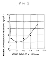
- Hydrogen absorbing alloys represented by the general formulae MmNi 3.8-z Co 0.5 Mn 0.4 Al 0.3 V2 and MmNi 3.8-z Co 0.5 Mn 0.4 Al 0.3 In2 were used for electrodes. While the atomic ratio z was changed within a range of from 0 to 0.4, the relation between the amount of substitution of V and In and the internal gas pressure of the battery charged with 1 CmA was examined. The results of examination are shwon in Figs. 2 and 3. The condition of production of alloys and electrodes, the condition of construction of batteries and the condition of measurement of internal gas pressure of the battery were the same as in the Example 1. As shown in Fig.
- the internal gas pressure of a battery using an alloy (MmNi 3.8 Co 0.5 Mn 0.4 Al 0.3 ) prepared without substitution of V for Ni was 18 kg/cm2 which was a very large value.
- the internal gas pressure of the battery was reduced to 6 kg/cm2 by substituting 0.02 atomic part V for Ni.
- the battery has excellent characteristics.
- the atomic ratio of V substituted for Ni was not larger than 0.3, the internal gas pressure of the battery was not higher than 10 kg/cm2.
- the safety vent was not opened though the battery was charged with 1 CmA, so that there was not problem in leakage of solution. Accordingly, the batteries have excellent characteristics.
- the atomic ratio of substitution of V is selected to be within a range of from 0.02 to 0.3.
- Fig. 3 shows the results of examination in the case where In is substituted for Ni. Also in the case of In, the same tendency as in the case of V was shown.
- the atomic ratio of substitution of In was selected to be within a range of from 0.02 to 0.1, the internal gas pressure of the battery charged with 1 CmA was not higher than 10 kg/cm2. Accordingly, it is preferable to select the atomic ratio of substitution of In to be within a range of from 0.02 to 0.1.
- a hydrogen absorbing alloy represented by the general formula of Al 1-x B x C y D z is used as the negative electrode, in which formula; A is selected from the group consisting of La, mixture of rare-earth elements, and misch metal; B is selected from the group consisting of Ti, Zr, Ca, Y, Hf and mixtures thereof; C is selected from the group consisting of Ni, Co, Mn, Al, Fe, Cu, Cr and mixtures thereof; D is selected from the group consisting of V, In, Tl, Ga and mixtures thereof; x has a value within a range of from 0 to 0.2
Abstract
Description
- The present invention relates to an alkaline storage battery using a negative electrode including, as a main constituent material, a hydrogen absorbing alloy capable of electrochemically absorbing/desorbing hydrogen and, more particularly, relates to an improvement in this type hydrogen absorbing alloy.
- Recently such a hydrogen absorbing alloy capable of electrochemically absorbing/desorbing hydrogen serving as an active material in a battery has attracted attention as a negative electrode material having high energy density. Investigation has been performed as to development of high-capacity storage batteries such as nickel-hydrogen storage battery or manganese dioxide-hydrogen storage battery using a combination of negative electrode of the type described above and available positive electrodes such as nickel positive electrode or manganese dioxide positive electrode. Conventionally, alloys having a CaCu₅ type crystal structure and represented by the general formula ABmCn have been proposed as hydrogen absorbing alloys to be used for negative electrode of this type nickel-hydrogen storage battery (Japanese Patent Unexamined Publication No. 60-89066 and U.S. Patent No. 4,487,817). In the above formula, A is selected one from the group consisting of misch metal, Y, Ti, Hf, Zr, Ca, Th, La and other rare-earth elements; B is at least one element selected from the group consisting of Ni,Co,Cu,Fe and Mn; m is an atomic ratio within the range made up as follows, m ≦ 3.5 for Ni, m ≦ 3.5 for Co, m ≦ 3.5 for Cu, m ≦ 2.0 for Fe, and m ≦ 1.0 for Mn; C is at least one element selected from the group of Al, Cr and Si; and n is an atomic ratio within the range made up as follows, 0.05 ≦ n ≦ 0.6 for Al, 0.05 ≦ n ≦ 0.5 for Cr, and 0.05 ≦ n ≦ 0.6 for Si. As shown in the aforementioned proposal, a part of an alloy, for example, an LaNi₅ alloy, is substituted by other elements to prepare a multicomponent alloy so as to prevent the alloy from becoming fine power by repetition of charging/discharging cycles and prevent the generated alloy powder from being oxidized to thereby prolong the cycle life of the battery.
- Further, in Japanese Patent Unexamined Publication No. 61-233969, a multicomponent alloy represented by the general formula LnNixMnyMz is proposed, in which formula Ln is a selected one of or a mixture of rare-earth elements; M is at least one element selected from the group consisting of Co, Cu, Fe, Al, Cr, Zn, Ti, Zr, Mo, Si and Mg; z is an atomic ratio within the range made up as follows, 0 ≦ z ≦ 0.2 for Co, 0 ≦ z ≦ 2 for Cu, 0 ≦ z ≦ 2 for Fe, 0 ≦ z ≦ 0.9 for Al, 0 ≦ z ≦ 1 for Cr, 0 ≦ z ≦ 0.5 for Zn, 0 ≦ z ≦ 0.3 for Ti, 0 ≦ z ≦ 0.3 for Zr, 0 ≦ z ≦ 0.3 for Mo, 0 ≦ z ≦ 0.5 for Si, and 0 ≦ z ≦ 0.3 for Mg; x is an atomic ratio of not smaller than 3.5; and y is an atomic ratio of not larger than 1.5. The purpose of such a multicomponent alloy is also to prevent the alloy from becoming fine powder due to repetition of charging/discharging cycles, that is, due to repetition of absorption/desorption of hydrogen, to thereby prolong the cycle life of the battery.
- In such a prior art configuration, although the problem with respect to the deterioration due to repetition of charging/discharging cycles could be solved, a new problem has been caused in that the internal gas pressure of the battery is so increased in a rapid charging period that it becomes difficult to perform the rapid charging.
- In general, in a nickel-hydrogen storage battery, the principle of the sealed cell design is the same as the oxygen extinguishing mechanism in a nickel-cadmium battery which has been proposed by Neumann, and the chargeable capacity of the negative electrode is established to be larger than that of the positive electrode. That is to say, the negative electrode is made so as not to be perfectly charged to have a not-charged portion remained even after the positive electrode has been perfectly charged, so that a hydrogen gas is prevented from being generated from the negative electrode in an overcharging period and at the same time, an oxygen gas generated from the positive electrode is absorbed to the negative electrode by the reaction represented by the following formula (1) to keep the sealing state of the battery,
MHx + O₂ → MHx-4 + 2H₂O (1)
in which M is a hydrogen absorbing alloy. - In the case where the negative electrode constituted by a hydrogen absorbing alloy is charged electrochemically (to absorb hydrogen) according to the formula (2), however, the hydrogen generation reaction represented by the formula (3) is carried out competitively in the last stage of the charging period.

H₂O + e⁻ → OH⁻ + 1/2H₂↑ (3) - The hydrogen generation reaction, which is a competitive reaction, is carried out in an earlier stage of the negative electrode charging period, as the negative electrode is charged more rapidly. Accordingly, even though the sealed nickel-hydrogen battery is constructed so that the chargeable capacity of the negative electrode is established to be larger than that of the positive electrode, a hydrogen gas is generated from the negative electrode in the rapid charging period and cannot be removed, thereby the internal gas pressure of the battery is increased remarkably. As the result, a gas as well as an alkaline electrolytic solution are leaked from a safety vent (in general, which is operated by pressure of 10 to 15 kg/cm²). There arises therefore a new problem in that deterioration of cycle life and lowering of safety are caused by the leakage of the electrolytic solution.
- An object of the present invention is to solve the aforementioned problems in the prior art.
- That is to say the object of the invention is to provide an excellent sealed alkaline storage battery in which generation of hydrogen from a hydrogen absorbing alloy constituting a negative electrode is suppressed in a rapid charging period to thereby prevent remarkable increase in internal gas pressure of the battery.
- To attain the foregoing objects, in an alkaline storage battery such as a nickel-hydrogen storage battery comprising a positive electrode including a metal oxide such as a nickel positive electrode having nickel oxide as an active material, a negative electrode including, as its main constituent material, a hydrogen absorbing alloy capable of electrochemically absorbing/desorbing hydrogen acting as an active material, an alkaline electrolytic solution, and a separator, according to the present invention, a hydrogen absorbing alloy having a CaCu₅ type crystal structure and being represented by the general formula A1-xBxCyDz is used as the negative electrodes, in which formula; A is selected from the group consisting of La, mixture of La and rare-earth elements, and misch metal; B is selected from the group consisting of Ti, Zr, Ca, Y, Hf and mixture thereof; x is an atomic ratio within the range 0 ≦ x ≦ 0.2; C is selected from the group consisting of Ni, Co, Mn, Al, Fe, Cu, Cr and mixtures thereof; y is an atomic ratio within the range made up as follows, y > 3.5 for Ni, y ≦ 1.0 for Co, y ≦ 0.6 for Mn, y ≦ 0.5 for Al, y ≦ 0.3 for Fe, y ≦ 1.0 for Cu, and y ≦ 0.3 for Cr; D is selected from the group consisting of V, In, Tl, Ga and mixtures thereof; z is an atomic ratio within the range made up as follows, 0.02 ≦ z ≦ 0.3 for V, 0.02 ≦ z ≦ 0.1 for In, 0.02 ≦ z ≦ 0.1 for Tl, and 0.02 ≦ z ≦ 0.1 for Ga; and (y+z) is an atomic ratio within a range of from 4.7 to 6.3, preferably from 4.7 to 5.3.
- According to the present invention, alternatively, the positive electrode may be a nickel electrode having nickel oxide as as active material or may be another metal oxide electrode having a metal oxide such as manganese dioxide as an active material. Further alternatively, the positive electrode may be a composite electrode containing nickel oxide and manganese oxide combined in a suitable ratio by weight.
- In the above configuration, according to the present invention, V is contained in the hydrogen absorbing alloy having a CaCu₅ type crystal structure to thereby increase the lattice constant of the
CaCu ₅ type crystal so as to increase the diffusion rate of hydrogen atoms in a solid phase so that no hydrogen gas is generated till the end of the charging period even when the battery is charged rapidly. Further, in the case where at least one element selected from the group consisting of In, Tl and Ga is added into the hydrogen absorbing alloy, the overvoltage in the hydrogen gas generation reaction becomes high and the generation of a hydrogen gas can be prevented till the end of the charging period even when the battery is charged rapidly. Accordingly, when a sealed storage battery is constituted by using a hydrogen absorbing alloy containing at least one element selected from the group consisting of V, In, Tl and Ga for the negative electrode thereof, a hydrogen gas is hardly generated from the negative electrode so that remarkable increase in internal gas pressure of the battery can be prevented even if the battery is subjected to rapid charging. -
- Fig. 1 is a view showing the structure of a sealed alkaline storage battery as an embodiment according to the present invention;
- Fig. 2 is a graph view showing the relation between the atomic ratio of substitutive V and the internal gas pressure of the battery in the case where the negative electrode is charged to 150% with 1 CmA; and
- Fig. 3 is a graph view showing the relation between the atomic ratio of substitutive In and the internal gas pressure of the battery.
- The present invention will be described hereunder with reference to the following examples.
- That selected, as the above element A, from the group consisting of La and available misch metal Mm (a mixture of rare-earth elements, such as for example La by about 25 wt%, Ce by about 52 wt%, Nd by about 18 wt%, and Pr by about 5 wt%), that selected, as the above element B, from the group consisting of Ti, Zr, Ca, Y and Hf, that selected, as the above element C, from the group consisting of Ni, Co, Mn, Al, Fe, Cu and Cr, and that selected, as the element D, from the group consisting of V, In, Tl and Ga were weighed and mixed in predetermined ratios to prepare various samples. The samples were put into an arc furnace. The furnace was evacuated to obtain a vacuum state of 10⁻⁴ to 10⁻⁵ torr. Then, the samples were heated so as to be melted by arc discharge under the reduced pressure in an atmosphere of an argon gas. The samples were inverted several times to thereby obtain homogeneous alloys. To make the alloys more homogeneous, the alloys were heated in a vacuum at 1050°C for 6 hours. Then, the alloys were ground roughly and then pulverized by a ball mill to prepare various kinds of fine powder having a particle diameter of not larger than 38 µm.
- Then, each of the various kinds of fine powder was dipped in a 7.2 N potassium hydroxide aqueous solution at 80°C for one hour to dissolve a part of the alloy surface. Then, the fine powder was washed with water and dried to prepare various kinds of fine powder having a rough alloy surface. The fine powder was mixed into an aqueous solution containing 1.5 wt% polyvinyl alcohol to prepare paste. Then, a foamed nickel porous matrix was filled with the paste, dried and pressed to prepare negative electrodes formed of various alloy compositions.
- The alloy content in each of the negative electrodes was selected to be 7.2 g. Table shows the compositions of the hydrogen absorbing alloys contained in the negative electrodes used in this example. Each of those negative electrodes 1 and a nickel
positive electrode 2 prepared by filling a known foamed metal with nickel hydroxide were inserted into acase 4 serving as a negative electrode terminal in the state that the negative electrode 1 and thepositive electrode 2 were wound spirally through aseparator 3 formed of sulfonated polypropylene non-woven fabric. Then, 2.2 cm³ of an alkaline electrolytic solution prepared by dissolving 40 g/1 of LiOH·H₂O in a 7.1 N KOH aqueous solution was injected into thecase 4 and sealed to prepare a 1000 mAh AA-size sealed nickel-hydrogen storage battery. The structure of the thus prepared battery is shown in Fig. 1. - In Fig. 1, a
safety vent 6 provided in the inner side of apositive electrode cap 5 is established to be operated by pressure of not lower than 30 kg/cm² for the purpose of measuring the internal gas pressure of the battery, though in general such a safety vent is established so as to be operated by pressure of 11 to 12 kg/cm². In the drawing, thereference numeral 7 designates a sealing plate, 8 designates an insulating gasket, and 9 designates a positive electrode collector for electrically connecting thepositive electrode 2 and thesealing plate 7. After the battery just assembled was charged with 0.1 CmA for 15 hours at 20°C and then discharged with 0.2 CmA, a 1 mm diameter hole was formed in the bottom portion of thecase 4. The battery was then fixed to a apparatus having a pressure sensor attached thereto and the internal gas pressure of the battery was measured when the battery was subject to 150% charging with 1 CmA. The results of measurement, together with the ratios of the alloy components, are shown in Table.

- In the Table, electrodes A to R are examples prepared according to the present invention, whereas electrodes S to W are comparative examples. The Sf value of the alloy used in each of the electrodes A to R is not larger than 2.5. The theoretical capacity in each of the electrodes A to R is in a range of from 220 to 250 mAh/g. The internal gas pressure in each of the batteries using the electrodes A to R according to the present invention was excellent and not higher than 7.8 kg/cm² though the battery was rapidly charged with 1 CmA. On the other hand, the internal gas pressure of the battery using the electrode W formed of an alloy not containing V, In, Tl or Ga was remarkably increased to 18 kg/cm² when the battery was charged with 1 CmA. In the case of using alloys, as shown in comparative examples S to V, containing Ni by an atomic ratio of 3.4, Co by an atomic ratio of 1.1, Mn by an atomic ratio of 0.7 and Al by an atomic ratio of 0.6, the internal gas pressure of the battery became not lower than 10 kg/cm² though the alloy contained V.
- Accordingly, the Sf value { = ln(PH/M = 0.75/PH/M= 0.25)} in each of the alloys obtained from the isothermal curve of pressure vs. composition is not smaller than 2.5, so that the theoretical capacity is not larger than 2000 mAh/g. Accordingly, the theoretical capacity of the negative electrode is lowered to increase the quantity of a hydrogen gas generated in an over-charging period, so that the internal gas pressure of the battery is increased. Though not shown in the Table, the internal gas pressure of a battery using an alloy containing Fe by an atomic ratio of 0.4, Cu by an atomic ratio of 1.0, and Cr by an atomic ratio of 0.4 became not lower than 10 kg/cm². Further, the amount of substitution of elements, such as Ti, Zr, Ca, Y and Hf, represented by B in the general formula, for elements represented by A is limited within a suitable range. If the atomic ratio x of substitution of these elements is not smaller than 0.2, the quantity of alloy phase effective for hydrogen absorption (CaCu₅ type crystal structure) is reduced so that the quantity of absorbed hydrogen is reduced. Consequently, in the case where the atomic ratio x was not smaller than 0.2, a large amount of hydrogen gas was generated to increase the internal gas pressure of the battery to 15 kg/cm² though the battery was assembled in the same condition. Accordingly, it is preferable that the atomic ratio x of substitution of elements Ti, Zr, Ca, Y and Hf for the element A is not larger than 0.2 even in the case where the alloy contains at least one element selected from the group consisting of V, In, Tl and Ga.
- Although this embodiment has shown the case where polyvinyl alcohol is used as a binding agent, it is to be understood that, according to the present invention, a hydrophobic resin such as polytetrafluoroethylene may be used as a binding agent to be disposed in a part of the electrode.
- Hydrogen absorbing alloys represented by the general formulae MmNi3.8-zCo0.5Mn0.4Al0.3V₂ and MmNi3.8-zCo0.5Mn0.4Al0.3In₂ were used for electrodes. While the atomic ratio z was changed within a range of from 0 to 0.4, the relation between the amount of substitution of V and In and the internal gas pressure of the battery charged with 1 CmA was examined. The results of examination are shwon in Figs. 2 and 3. The condition of production of alloys and electrodes, the condition of construction of batteries and the condition of measurement of internal gas pressure of the battery were the same as in the Example 1. As shown in Fig. 2, the internal gas pressure of a battery using an alloy (MmNi3.8Co0.5Mn0.4Al0.3) prepared without substitution of V for Ni was 18 kg/cm² which was a very large value. However, the internal gas pressure of the battery was reduced to 6 kg/cm² by substituting 0.02 atomic part V for Ni. In this case, the battery has excellent characteristics. When the atomic ratio of V substituted for Ni was not larger than 0.3, the internal gas pressure of the battery was not higher than 10 kg/cm². In this case, the safety vent was not opened though the battery was charged with 1 CmA, so that there was not problem in leakage of solution. Accordingly, the batteries have excellent characteristics. However, when the atomic ratio of substitution of V was 0.4, the internal gas pressure of the battery was 14 kg/cm². Accordingly, it is preferable that the atomic ratio of substitution of V is selected to be within a range of from 0.02 to 0.3. Fig. 3 shows the results of examination in the case where In is substituted for Ni. Also in the case of In, the same tendency as in the case of V was shown. When the atomic ratio of substitution of In was selected to be within a range of from 0.02 to 0.1, the internal gas pressure of the battery charged with 1 CmA was not higher than 10 kg/cm². Accordingly, it is preferable to select the atomic ratio of substitution of In to be within a range of from 0.02 to 0.1.
- As described above, in an alkaline storage battery comprising a positive electrode including a metal oxide such as nickel oxide, manganese oxide or the like, as a main constituent material, a negative electrode including, as a main constituent material, a hydrogen absorbing alloy capable of electrochemically absorbing/ desorbing hydrogen serving as an active material, an alkaline electrolytic solution, and a separator, according to the present invention, a hydrogen absorbing alloy represented by the general formula of Al1-xBxCyDz is used as the negative electrode, in which formula; A is selected from the group consisting of La, mixture of rare-earth elements, and misch metal; B is selected from the group consisting of Ti, Zr, Ca, Y, Hf and mixtures thereof; C is selected from the group consisting of Ni, Co, Mn, Al, Fe, Cu, Cr and mixtures thereof; D is selected from the group consisting of V, In, Tl, Ga and mixtures thereof; x has a value within a range of from 0 to 0.2; y has a value within the range made up as follows, y >3.5 for Ni, y ≦ 1.0 for Co, y ≦ 0.6 for Mn, y ≦ 0.5 for Al, y ≦ 0.3 for Fe, y ≦ 1.0 for Cu, and y ≦ 0.3 for Cr; and z has a value within the range made up as follows, 0.02 ≦ z ≦ 0.3 for V, 0.02 ≦ z ≦ 0.1 for In, 0.02 ≦ z ≦ 0.1 for Tl, and 0.02 ≦ z ≦ 0.1 for Ga. Accordingly, generation of a hydrogen gas from the hydrogen absorbing alloy of the negative electrode can be limited. There arises an effect in that the internal gas pressure of the battery is not over 10 kg/cm². Accordingly, there is no leakage of the alkaline electrolytic solution entrained with a gas from the safety vent. Consequently, according to the present invention, a sealed alkaline storage battery excellent in safety can be provided.
Claims (18)
Applications Claiming Priority (2)
| Application Number | Priority Date | Filing Date | Title |
|---|---|---|---|
| JP1043710A JP2926734B2 (en) | 1989-02-23 | 1989-02-23 | Alkaline storage battery using hydrogen storage alloy |
| JP43710/89 | 1989-02-23 |
Publications (4)
| Publication Number | Publication Date |
|---|---|
| EP0383991A2 true EP0383991A2 (en) | 1990-08-29 |
| EP0383991A3 EP0383991A3 (en) | 1990-09-12 |
| EP0383991B1 EP0383991B1 (en) | 1994-01-19 |
| EP0383991B2 EP0383991B2 (en) | 1997-04-09 |
Family
ID=12671365
Family Applications (1)
| Application Number | Title | Priority Date | Filing Date |
|---|---|---|---|
| EP89109751A Expired - Lifetime EP0383991B2 (en) | 1989-02-23 | 1989-05-30 | Alkaline storage battery using hydrogen absorbing alloy |
Country Status (4)
| Country | Link |
|---|---|
| US (1) | US4925748A (en) |
| EP (1) | EP0383991B2 (en) |
| JP (1) | JP2926734B2 (en) |
| DE (1) | DE68912566T3 (en) |
Cited By (4)
| Publication number | Priority date | Publication date | Assignee | Title |
|---|---|---|---|---|
| EP0627779A1 (en) * | 1993-05-31 | 1994-12-07 | SANYO ELECTRIC Co., Ltd. | Sealed type nickel-metal hydride alkaline storage cell |
| US5389333A (en) * | 1993-08-31 | 1995-02-14 | Central Iron & Steel Research Institute Of Ministry Of Metallurgical Industry | Hydrogen storage alloys |
| US6013387A (en) * | 1998-06-22 | 2000-01-11 | Li-Ho Yao | Hydrogen absorbing alloy for battery application |
| SG101413A1 (en) * | 1995-04-06 | 2004-01-30 | Treibacher Auermet Prod Gmbh | Alkaline metal oxide/metal hydride battery |
Families Citing this family (21)
| Publication number | Priority date | Publication date | Assignee | Title |
|---|---|---|---|---|
| US5346781A (en) * | 1989-02-23 | 1994-09-13 | Matsushita Electric Industrial Co., Ltd. | Alkaline storage battery |
| NL8901776A (en) * | 1989-07-11 | 1991-02-01 | Philips Nv | ELECTROCHEMICAL CELL. |
| DE69014183T2 (en) * | 1989-09-18 | 1995-06-22 | Toshiba Kawasaki Kk | Nickel-metal hydride secondary cell. |
| JP2980328B2 (en) * | 1989-09-29 | 1999-11-22 | 株式会社東芝 | Hydrogen storage alloy for battery, method for producing the same, and nickel-metal hydride secondary battery |
| US6001810A (en) * | 1989-11-20 | 1999-12-14 | Eli Lilly And Company | Methods for treating retroviral infection |
| JP3005247B2 (en) * | 1990-05-31 | 2000-01-31 | 三洋電機株式会社 | Hydrogen storage alloy |
| NL9001677A (en) * | 1990-07-24 | 1992-02-17 | Koninkl Philips Electronics Nv | ELECTROCHEMICAL CELL WITH HYDRIDE FORMING INTERMETALLIC COMPOUND. |
| JPH04137368A (en) * | 1990-09-26 | 1992-05-12 | Matsushita Electric Ind Co Ltd | Nickel-hydrogen storage battery and its manufacture |
| US5264301A (en) * | 1992-04-14 | 1993-11-23 | Globe-Union Inc. | Metal oxide-hydrogen battery incorporating a mechanism for maintaining a constant pressure in the battery |
| JP3438142B2 (en) * | 1992-09-18 | 2003-08-18 | 松下電器産業株式会社 | Medium / large capacity sealed metal oxide / hydrogen storage battery |
| JP2903913B2 (en) * | 1992-11-10 | 1999-06-14 | 松下電器産業株式会社 | Storage battery system |
| US5547784A (en) * | 1993-01-18 | 1996-08-20 | Matsushita Electric Industrial Co., Ltd. | Alkaline storage battery and method for producing the same |
| US5376474A (en) * | 1993-02-05 | 1994-12-27 | Sanyo Electric Co., Ltd. | Hydrogen-absorbing alloy for a negative electrode and manufacturing method therefor |
| DE69426613T2 (en) * | 1993-03-01 | 2001-08-30 | Matsushita Electric Ind Co Ltd | Process and manufacture of a hydrogen storage alloy |
| US5525435A (en) * | 1994-07-11 | 1996-06-11 | Eveready Battery Company, Inc. | Hydrogen storage materials |
| US6048644A (en) * | 1997-03-24 | 2000-04-11 | Matsushita Electric Industrial Co., Ltd. | Hydrogen storage alloy electrode |
| WO2000001023A1 (en) * | 1998-06-26 | 2000-01-06 | Sanyo Electric Co., Ltd. | Hydrogen absorbing alloy for alkaline storage battery and method for preparing the same |
| US6492057B1 (en) * | 1999-04-14 | 2002-12-10 | Ovonic Battery Company, Inc. | Electrochemical cell having reduced cell pressure |
| JP2001015142A (en) | 1999-06-30 | 2001-01-19 | Mitsubishi Heavy Ind Ltd | Running method of fuel-cell vehicle and fuel-cell vehicle |
| US10193154B2 (en) | 2013-01-31 | 2019-01-29 | Medtronic, Inc. | Cathode composition for primary battery |
| JP2018147626A (en) * | 2017-03-02 | 2018-09-20 | トヨタ自動車株式会社 | Alkaline secondary battery |
Citations (14)
| Publication number | Priority date | Publication date | Assignee | Title |
|---|---|---|---|---|
| FR2311858A1 (en) * | 1975-05-23 | 1976-12-17 | Anvar | LANTHANE AND NICKEL-BASED ALLOYS AND THEIR ELECTROCHEMICAL APPLICATIONS |
| FR2382774A2 (en) * | 1977-03-02 | 1978-09-29 | Anvar | Alloy based on nickel and lanthanum, for use as battery electrode - contains substits. to improve hydrogen absorption |
| FR2399484A1 (en) * | 1977-08-02 | 1979-03-02 | Anvar | NEW LANTHAN AND NICKEL-BASED ALLOYS, THEIR MANUFACTURING AND THEIR ELECTROCHEMICAL APPLICATIONS |
| JPS60250558A (en) * | 1984-05-25 | 1985-12-11 | Matsushita Electric Ind Co Ltd | Enclosed type alkaline storage battery |
| JPS6191863A (en) * | 1984-10-11 | 1986-05-09 | Matsushita Electric Ind Co Ltd | Sealed alkaline storage battery |
| JPS61168871A (en) * | 1985-01-19 | 1986-07-30 | Sanyo Electric Co Ltd | Hydrogen occlusion electrode |
| EP0206776A2 (en) * | 1985-06-21 | 1986-12-30 | Kabushiki Kaisha Toshiba | Rechargeable electrochemical cell with a negative electrode comprising a hydrogen absorbing alloy including rare earth component |
| JPS62139255A (en) * | 1985-12-11 | 1987-06-22 | Matsushita Electric Ind Co Ltd | Manufacture of hydrogen absorbing electrode |
| JPS62249357A (en) * | 1986-04-19 | 1987-10-30 | Sanyo Electric Co Ltd | Hydrogen storage electrode |
| JPS62259344A (en) * | 1986-05-02 | 1987-11-11 | Sanyo Electric Co Ltd | Hydrogen absorbing electrode |
| JPS62271349A (en) * | 1986-05-19 | 1987-11-25 | Sanyo Electric Co Ltd | Hydrogen occlusion electrode |
| JPS62271348A (en) * | 1986-05-19 | 1987-11-25 | Sanyo Electric Co Ltd | Hydrogen occlusion electrode |
| JPS63304570A (en) * | 1987-06-03 | 1988-12-12 | Matsushita Electric Ind Co Ltd | Hydrogen occlusion electrode |
| JPS63314764A (en) * | 1987-06-17 | 1988-12-22 | Matsushita Electric Ind Co Ltd | Hydrogen absorbing electrode |
Family Cites Families (9)
| Publication number | Priority date | Publication date | Assignee | Title |
|---|---|---|---|---|
| US3850694A (en) * | 1972-11-27 | 1974-11-26 | Communications Satellite Corp | Low pressure nickel hydrogen cell |
| US4214043A (en) * | 1978-02-03 | 1980-07-22 | U.S. Philips Corporation | Rechargeable electrochemical cell |
| US4312928A (en) * | 1978-05-04 | 1982-01-26 | U.S. Philips Corporation | Rechargeable electrochemical cell |
| NL8303630A (en) * | 1983-10-21 | 1985-05-17 | Philips Nv | ELECTROCHEMICAL CELL WITH STABLE HYDRIDE-FORMING MATERIALS. |
| FR2569059B1 (en) * | 1984-08-10 | 1992-08-07 | Sanyo Electric Co | ALKALINE METAL / HYDROGEN ACCUMULATOR |
| NL8601675A (en) * | 1986-06-26 | 1988-01-18 | Philips Nv | ELECTROCHEMICAL CELL. |
| NL8601674A (en) * | 1986-06-26 | 1988-01-18 | Philips Nv | ELECTROCHEMICAL CELL. |
| DE3776300D1 (en) * | 1986-12-08 | 1992-03-05 | Matsushita Electric Ind Co Ltd | GAS-TIGHT ACCUMULATOR AND METHOD FOR PRODUCING ITS ELECTRODE. |
| KR920007380B1 (en) * | 1987-02-17 | 1992-08-31 | 산요 덴끼 가부시끼가이샤 | Making method of alkali battery |
-
1989
- 1989-02-23 JP JP1043710A patent/JP2926734B2/en not_active Expired - Lifetime
- 1989-05-24 US US07/356,229 patent/US4925748A/en not_active Expired - Lifetime
- 1989-05-30 EP EP89109751A patent/EP0383991B2/en not_active Expired - Lifetime
- 1989-05-30 DE DE68912566T patent/DE68912566T3/en not_active Expired - Lifetime
Patent Citations (14)
| Publication number | Priority date | Publication date | Assignee | Title |
|---|---|---|---|---|
| FR2311858A1 (en) * | 1975-05-23 | 1976-12-17 | Anvar | LANTHANE AND NICKEL-BASED ALLOYS AND THEIR ELECTROCHEMICAL APPLICATIONS |
| FR2382774A2 (en) * | 1977-03-02 | 1978-09-29 | Anvar | Alloy based on nickel and lanthanum, for use as battery electrode - contains substits. to improve hydrogen absorption |
| FR2399484A1 (en) * | 1977-08-02 | 1979-03-02 | Anvar | NEW LANTHAN AND NICKEL-BASED ALLOYS, THEIR MANUFACTURING AND THEIR ELECTROCHEMICAL APPLICATIONS |
| JPS60250558A (en) * | 1984-05-25 | 1985-12-11 | Matsushita Electric Ind Co Ltd | Enclosed type alkaline storage battery |
| JPS6191863A (en) * | 1984-10-11 | 1986-05-09 | Matsushita Electric Ind Co Ltd | Sealed alkaline storage battery |
| JPS61168871A (en) * | 1985-01-19 | 1986-07-30 | Sanyo Electric Co Ltd | Hydrogen occlusion electrode |
| EP0206776A2 (en) * | 1985-06-21 | 1986-12-30 | Kabushiki Kaisha Toshiba | Rechargeable electrochemical cell with a negative electrode comprising a hydrogen absorbing alloy including rare earth component |
| JPS62139255A (en) * | 1985-12-11 | 1987-06-22 | Matsushita Electric Ind Co Ltd | Manufacture of hydrogen absorbing electrode |
| JPS62249357A (en) * | 1986-04-19 | 1987-10-30 | Sanyo Electric Co Ltd | Hydrogen storage electrode |
| JPS62259344A (en) * | 1986-05-02 | 1987-11-11 | Sanyo Electric Co Ltd | Hydrogen absorbing electrode |
| JPS62271349A (en) * | 1986-05-19 | 1987-11-25 | Sanyo Electric Co Ltd | Hydrogen occlusion electrode |
| JPS62271348A (en) * | 1986-05-19 | 1987-11-25 | Sanyo Electric Co Ltd | Hydrogen occlusion electrode |
| JPS63304570A (en) * | 1987-06-03 | 1988-12-12 | Matsushita Electric Ind Co Ltd | Hydrogen occlusion electrode |
| JPS63314764A (en) * | 1987-06-17 | 1988-12-22 | Matsushita Electric Ind Co Ltd | Hydrogen absorbing electrode |
Non-Patent Citations (8)
| Title |
|---|
| CHEMICAL ABSTRACTS, vol. 106, no. 2, 12th January 1987, page 151, abstract no. 7556b, Columbus, Ohio, US; & JP-A-61 168 871 (SANYO ELECTRIC CO., LTD) 30-07-1986 * |
| CHEMICAL ABSTRACTS, vol. 108, no. 14, 4th April 1988, page 213, abstract no. 115876f, Columbus, Ohio, US; & JP-A-62 259 344 (SANYO ELECTRIC CO., LTD) 11-11-1987 * |
| PATENT ABSTRACTS OF JAPAN, vol. 10, no. 117 (E-400)[2174], 2nd May 1986; & JP-A-60 250 558 (MATSUSHITA DENKI SANGYO K.K.) 11-12-1985 * |
| PATENT ABSTRACTS OF JAPAN, vol. 10, no. 268 (E-436)[2324], 12th September 1986; & JP-A-61 91 863 (MATSUSHITA ELECTRIC IND. CO., LTD) 09-05-1986 * |
| PATENT ABSTRACTS OF JAPAN, vol. 11, no. 367 (E-561)[2814], 28th November 1987; & JP-A-62 139 255 (MATSUSHITA ELECTRIC IND. CO., LTD) 22-06-1987 * |
| PATENT ABSTRACTS OF JAPAN, vol. 12, no. 124 (E-601)[2971], 16th April 1988; & JP-A-62 249 357 (SANYO ELECTRIC CO., LTD) 30-10-1987 * |
| PATENT ABSTRACTS OF JAPAN, vol. 12, no. 158 (E-608)[3005], 13th May 1988; & JP-A-62 271 348 (SANYO ELECTRIC CO., LTD) 25-11-1987 * |
| PATENT ABSTRACTS OF JAPAN, vol. 12, no. 158 (E-608)[3005], 13th May 1988; & JP-A-62 271 349 (SANYO ELECTRIC CO., LTD) 25-11-1987 * |
Cited By (6)
| Publication number | Priority date | Publication date | Assignee | Title |
|---|---|---|---|---|
| EP0627779A1 (en) * | 1993-05-31 | 1994-12-07 | SANYO ELECTRIC Co., Ltd. | Sealed type nickel-metal hydride alkaline storage cell |
| US5389333A (en) * | 1993-08-31 | 1995-02-14 | Central Iron & Steel Research Institute Of Ministry Of Metallurgical Industry | Hydrogen storage alloys |
| SG101413A1 (en) * | 1995-04-06 | 2004-01-30 | Treibacher Auermet Prod Gmbh | Alkaline metal oxide/metal hydride battery |
| US6013387A (en) * | 1998-06-22 | 2000-01-11 | Li-Ho Yao | Hydrogen absorbing alloy for battery application |
| GB2339206A (en) * | 1998-06-22 | 2000-01-19 | Yao Li Ho | Hydrogen absorbing alloy for battery applications |
| GB2339206B (en) * | 1998-06-22 | 2000-06-28 | Yao Li Ho | A hydrogen absorbing alloy for battery application |
Also Published As
| Publication number | Publication date |
|---|---|
| JP2926734B2 (en) | 1999-07-28 |
| JPH02223150A (en) | 1990-09-05 |
| EP0383991A3 (en) | 1990-09-12 |
| US4925748A (en) | 1990-05-15 |
| EP0383991B1 (en) | 1994-01-19 |
| DE68912566T2 (en) | 1994-06-30 |
| EP0383991B2 (en) | 1997-04-09 |
| DE68912566D1 (en) | 1994-03-03 |
| DE68912566T3 (en) | 1997-11-13 |
Similar Documents
| Publication | Publication Date | Title |
|---|---|---|
| US4925748A (en) | Alkaline storage battery using hydrogen absorbing alloy | |
| EP0522297B1 (en) | Hydrogen storage electrode | |
| JP2771592B2 (en) | Hydrogen storage alloy electrode for alkaline storage batteries | |
| EP0386305A1 (en) | Alkaline storage battery and method of producing negative electrode thereof | |
| US5242656A (en) | Active material of hydrogen storage alloy electrode | |
| US4702978A (en) | Electrochemical cell | |
| JPH0677451B2 (en) | Manufacturing method of hydrogen storage electrode | |
| US6071644A (en) | Metal hydride storage cell and method of producing hydrogen absorbing alloy electrode | |
| JP2965475B2 (en) | Hydrogen storage alloy | |
| US20100216018A1 (en) | Hydrogen-absorbing alloy and alkaline storage battery having the alloy | |
| US5242766A (en) | Hydrogen-occlusion electrode | |
| JPH0855635A (en) | Metallic oxide/metal hydride-storage battery closed hermetically | |
| US6197448B1 (en) | Hydrogen storage alloy | |
| JP2680623B2 (en) | Hydrogen storage alloy electrode | |
| JP2740175B2 (en) | Hydrogen storage alloy electrode for alkaline storage batteries | |
| KR0137797B1 (en) | Manufacturing method of electrode for the secondary battery using the hydrogen storage alloy | |
| JP2713881B2 (en) | Sealed metal oxide / hydrogen battery | |
| KR100207618B1 (en) | Negative electrode manufacturing method and secondary battery having it | |
| JPH0690924B2 (en) | Storage battery electrode | |
| JP3343417B2 (en) | Metal oxide / hydrogen secondary battery | |
| Wasz et al. | Sn-substituted LaNi5 alloys for metal hydride electrodes | |
| JPH0613077A (en) | Hydrogen storage electrode | |
| JPH0690922B2 (en) | Sealed alkaline storage battery | |
| JP3146063B2 (en) | Metal oxide / hydrogen secondary batteries | |
| JPH06145849A (en) | Hydrogen storage alloy electrode |
Legal Events
| Date | Code | Title | Description |
|---|---|---|---|
| PUAI | Public reference made under article 153(3) epc to a published international application that has entered the european phase |
Free format text: ORIGINAL CODE: 0009012 |
|
| PUAL | Search report despatched |
Free format text: ORIGINAL CODE: 0009013 |
|
| AK | Designated contracting states |
Kind code of ref document: A2 Designated state(s): BE DE FR GB IT NL |
|
| AK | Designated contracting states |
Kind code of ref document: A3 Designated state(s): BE DE FR GB IT NL |
|
| 17P | Request for examination filed |
Effective date: 19901015 |
|
| 17Q | First examination report despatched |
Effective date: 19911018 |
|
| GRAA | (expected) grant |
Free format text: ORIGINAL CODE: 0009210 |
|
| ITF | It: translation for a ep patent filed |
Owner name: BARZANO' E ZANARDO ROMA S.P.A. |
|
| AK | Designated contracting states |
Kind code of ref document: B1 Designated state(s): BE DE FR GB IT NL |
|
| REF | Corresponds to: |
Ref document number: 68912566 Country of ref document: DE Date of ref document: 19940303 |
|
| ET | Fr: translation filed | ||
| ITTA | It: last paid annual fee | ||
| PLBI | Opposition filed |
Free format text: ORIGINAL CODE: 0009260 |
|
| 26 | Opposition filed |
Opponent name: ALCATEL ALSTHOM CIE. GEN. D'ELECTRICITE Effective date: 19941012 |
|
| NLR1 | Nl: opposition has been filed with the epo |
Opponent name: ALCATEL ALSTHOM CIE. GEN. D'ELECTRICITE |
|
| PLAW | Interlocutory decision in opposition |
Free format text: ORIGINAL CODE: EPIDOS IDOP |
|
| PLAW | Interlocutory decision in opposition |
Free format text: ORIGINAL CODE: EPIDOS IDOP |
|
| PUAH | Patent maintained in amended form |
Free format text: ORIGINAL CODE: 0009272 |
|
| STAA | Information on the status of an ep patent application or granted ep patent |
Free format text: STATUS: PATENT MAINTAINED AS AMENDED |
|
| ITF | It: translation for a ep patent filed |
Owner name: 0403;01RMFBARZANO' E ZANARDO ROMA S.P.A. |
|
| 27A | Patent maintained in amended form |
Effective date: 19970409 |
|
| AK | Designated contracting states |
Kind code of ref document: B2 Designated state(s): BE DE FR GB IT NL |
|
| NLR2 | Nl: decision of opposition | ||
| NLR3 | Nl: receipt of modified translations in the netherlands language after an opposition procedure | ||
| ET3 | Fr: translation filed ** decision concerning opposition | ||
| REG | Reference to a national code |
Ref country code: GB Ref legal event code: IF02 |
|
| PGFP | Annual fee paid to national office [announced via postgrant information from national office to epo] |
Ref country code: DE Payment date: 20080605 Year of fee payment: 20 |
|
| PGFP | Annual fee paid to national office [announced via postgrant information from national office to epo] |
Ref country code: IT Payment date: 20080527 Year of fee payment: 20 |
|
| PGFP | Annual fee paid to national office [announced via postgrant information from national office to epo] |
Ref country code: NL Payment date: 20080501 Year of fee payment: 20 |
|
| PGFP | Annual fee paid to national office [announced via postgrant information from national office to epo] |
Ref country code: GB Payment date: 20080604 Year of fee payment: 20 |
|
| PGFP | Annual fee paid to national office [announced via postgrant information from national office to epo] |
Ref country code: BE Payment date: 20080709 Year of fee payment: 20 |
|
| BE20 | Be: patent expired |
Owner name: *MATSUSHITA ELECTRIC INDUSTRIAL CO. LTD Effective date: 20090530 |
|
| REG | Reference to a national code |
Ref country code: GB Ref legal event code: PE20 Expiry date: 20090529 |
|
| PG25 | Lapsed in a contracting state [announced via postgrant information from national office to epo] |
Ref country code: NL Free format text: LAPSE BECAUSE OF EXPIRATION OF PROTECTION Effective date: 20090530 |
|
| NLV7 | Nl: ceased due to reaching the maximum lifetime of a patent |
Effective date: 20090530 |
|
| PG25 | Lapsed in a contracting state [announced via postgrant information from national office to epo] |
Ref country code: GB Free format text: LAPSE BECAUSE OF EXPIRATION OF PROTECTION Effective date: 20090529 |
|
| PGFP | Annual fee paid to national office [announced via postgrant information from national office to epo] |
Ref country code: FR Payment date: 20080514 Year of fee payment: 20 |