KR920007380B1 - Making method of alkali battery - Google Patents
Making method of alkali battery Download PDFInfo
- Publication number
- KR920007380B1 KR920007380B1 KR1019880001509A KR880001509A KR920007380B1 KR 920007380 B1 KR920007380 B1 KR 920007380B1 KR 1019880001509 A KR1019880001509 A KR 1019880001509A KR 880001509 A KR880001509 A KR 880001509A KR 920007380 B1 KR920007380 B1 KR 920007380B1
- Authority
- KR
- South Korea
- Prior art keywords
- storage battery
- alkaline storage
- battery according
- electrode
- water
- Prior art date
Links
Images


Classifications
-
- H—ELECTRICITY
- H01—ELECTRIC ELEMENTS
- H01M—PROCESSES OR MEANS, e.g. BATTERIES, FOR THE DIRECT CONVERSION OF CHEMICAL ENERGY INTO ELECTRICAL ENERGY
- H01M4/00—Electrodes
- H01M4/02—Electrodes composed of, or comprising, active material
- H01M4/24—Electrodes for alkaline accumulators
- H01M4/26—Processes of manufacture
-
- H—ELECTRICITY
- H01—ELECTRIC ELEMENTS
- H01M—PROCESSES OR MEANS, e.g. BATTERIES, FOR THE DIRECT CONVERSION OF CHEMICAL ENERGY INTO ELECTRICAL ENERGY
- H01M4/00—Electrodes
- H01M4/02—Electrodes composed of, or comprising, active material
- H01M4/62—Selection of inactive substances as ingredients for active masses, e.g. binders, fillers
- H01M4/621—Binders
- H01M4/622—Binders being polymers
-
- H—ELECTRICITY
- H01—ELECTRIC ELEMENTS
- H01M—PROCESSES OR MEANS, e.g. BATTERIES, FOR THE DIRECT CONVERSION OF CHEMICAL ENERGY INTO ELECTRICAL ENERGY
- H01M10/00—Secondary cells; Manufacture thereof
- H01M10/34—Gastight accumulators
-
- H—ELECTRICITY
- H01—ELECTRIC ELEMENTS
- H01M—PROCESSES OR MEANS, e.g. BATTERIES, FOR THE DIRECT CONVERSION OF CHEMICAL ENERGY INTO ELECTRICAL ENERGY
- H01M4/00—Electrodes
- H01M4/02—Electrodes composed of, or comprising, active material
- H01M4/24—Electrodes for alkaline accumulators
-
- H—ELECTRICITY
- H01—ELECTRIC ELEMENTS
- H01M—PROCESSES OR MEANS, e.g. BATTERIES, FOR THE DIRECT CONVERSION OF CHEMICAL ENERGY INTO ELECTRICAL ENERGY
- H01M4/00—Electrodes
- H01M4/02—Electrodes composed of, or comprising, active material
- H01M4/24—Electrodes for alkaline accumulators
- H01M4/246—Cadmium electrodes
-
- H—ELECTRICITY
- H01—ELECTRIC ELEMENTS
- H01M—PROCESSES OR MEANS, e.g. BATTERIES, FOR THE DIRECT CONVERSION OF CHEMICAL ENERGY INTO ELECTRICAL ENERGY
- H01M4/00—Electrodes
- H01M4/02—Electrodes composed of, or comprising, active material
- H01M4/64—Carriers or collectors
- H01M4/70—Carriers or collectors characterised by shape or form
- H01M4/72—Grids
- H01M4/74—Meshes or woven material; Expanded metal
- H01M4/742—Meshes or woven material; Expanded metal perforated material
-
- H—ELECTRICITY
- H01—ELECTRIC ELEMENTS
- H01M—PROCESSES OR MEANS, e.g. BATTERIES, FOR THE DIRECT CONVERSION OF CHEMICAL ENERGY INTO ELECTRICAL ENERGY
- H01M50/00—Constructional details or processes of manufacture of the non-active parts of electrochemical cells other than fuel cells, e.g. hybrid cells
- H01M50/40—Separators; Membranes; Diaphragms; Spacing elements inside cells
- H01M50/46—Separators, membranes or diaphragms characterised by their combination with electrodes
-
- H—ELECTRICITY
- H01—ELECTRIC ELEMENTS
- H01M—PROCESSES OR MEANS, e.g. BATTERIES, FOR THE DIRECT CONVERSION OF CHEMICAL ENERGY INTO ELECTRICAL ENERGY
- H01M10/00—Secondary cells; Manufacture thereof
- H01M10/42—Methods or arrangements for servicing or maintenance of secondary cells or secondary half-cells
- H01M10/52—Removing gases inside the secondary cell, e.g. by absorption
- H01M10/526—Removing gases inside the secondary cell, e.g. by absorption by gas recombination on the electrode surface or by structuring the electrode surface to improve gas recombination
-
- H—ELECTRICITY
- H01—ELECTRIC ELEMENTS
- H01M—PROCESSES OR MEANS, e.g. BATTERIES, FOR THE DIRECT CONVERSION OF CHEMICAL ENERGY INTO ELECTRICAL ENERGY
- H01M2300/00—Electrolytes
- H01M2300/0002—Aqueous electrolytes
- H01M2300/0014—Alkaline electrolytes
-
- H—ELECTRICITY
- H01—ELECTRIC ELEMENTS
- H01M—PROCESSES OR MEANS, e.g. BATTERIES, FOR THE DIRECT CONVERSION OF CHEMICAL ENERGY INTO ELECTRICAL ENERGY
- H01M4/00—Electrodes
- H01M4/02—Electrodes composed of, or comprising, active material
- H01M4/62—Selection of inactive substances as ingredients for active masses, e.g. binders, fillers
- H01M4/624—Electric conductive fillers
- H01M4/625—Carbon or graphite
-
- H—ELECTRICITY
- H01—ELECTRIC ELEMENTS
- H01M—PROCESSES OR MEANS, e.g. BATTERIES, FOR THE DIRECT CONVERSION OF CHEMICAL ENERGY INTO ELECTRICAL ENERGY
- H01M6/00—Primary cells; Manufacture thereof
- H01M6/04—Cells with aqueous electrolyte
- H01M6/06—Dry cells, i.e. cells wherein the electrolyte is rendered non-fluid
- H01M6/10—Dry cells, i.e. cells wherein the electrolyte is rendered non-fluid with wound or folded electrodes
-
- Y—GENERAL TAGGING OF NEW TECHNOLOGICAL DEVELOPMENTS; GENERAL TAGGING OF CROSS-SECTIONAL TECHNOLOGIES SPANNING OVER SEVERAL SECTIONS OF THE IPC; TECHNICAL SUBJECTS COVERED BY FORMER USPC CROSS-REFERENCE ART COLLECTIONS [XRACs] AND DIGESTS
- Y02—TECHNOLOGIES OR APPLICATIONS FOR MITIGATION OR ADAPTATION AGAINST CLIMATE CHANGE
- Y02E—REDUCTION OF GREENHOUSE GAS [GHG] EMISSIONS, RELATED TO ENERGY GENERATION, TRANSMISSION OR DISTRIBUTION
- Y02E60/00—Enabling technologies; Technologies with a potential or indirect contribution to GHG emissions mitigation
- Y02E60/10—Energy storage using batteries
-
- Y—GENERAL TAGGING OF NEW TECHNOLOGICAL DEVELOPMENTS; GENERAL TAGGING OF CROSS-SECTIONAL TECHNOLOGIES SPANNING OVER SEVERAL SECTIONS OF THE IPC; TECHNICAL SUBJECTS COVERED BY FORMER USPC CROSS-REFERENCE ART COLLECTIONS [XRACs] AND DIGESTS
- Y02—TECHNOLOGIES OR APPLICATIONS FOR MITIGATION OR ADAPTATION AGAINST CLIMATE CHANGE
- Y02P—CLIMATE CHANGE MITIGATION TECHNOLOGIES IN THE PRODUCTION OR PROCESSING OF GOODS
- Y02P70/00—Climate change mitigation technologies in the production process for final industrial or consumer products
- Y02P70/50—Manufacturing or production processes characterised by the final manufactured product
Landscapes
- Chemical & Material Sciences (AREA)
- Chemical Kinetics & Catalysis (AREA)
- Electrochemistry (AREA)
- General Chemical & Material Sciences (AREA)
- Engineering & Computer Science (AREA)
- Manufacturing & Machinery (AREA)
- Battery Electrode And Active Subsutance (AREA)
- Secondary Cells (AREA)
Abstract
내용 없음.No content.
Description
제1도는 본 발명의 알칼리 축전지의 종단면부를 보인 사시도.1 is a perspective view showing a longitudinal section of an alkaline storage battery of the present invention.
제2도는 본 발명의 전지 A1및 A2, A3의 충전시간과 전지내 가스압과의 관계를 나타낸 그래프.2 is a graph showing the relationship between the charging time of the batteries A 1 and A 2 and A 3 of the present invention and the gas pressure in the battery.
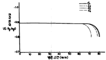
제3도는 본 발명전지 A1의 전극 a1및 비교전지 A3의 전극 a3의 방전시간과 전극전위의 관계를 나타낸 그래프.The third turning a graph showing the relationship between the electrode of the present invention cell A and comparative cells 1 a 1 a 3 A three-electrode-discharge time and the electrode potential of the.
제4도는 본 발명전지 B1및 비교전지 B2의 싸이클수와 전지용량 비의 관계를 나타낸 그래프.4 is a graph showing the relationship between the number of cycles and the battery capacity ratio of the battery B 1 and the comparative battery B 2 of the present invention.
제5도는 본 발명전지 C1및 비교전지 C2, C3, C4, C5의 충전 시간과 전지내 가스압과의 관계를 나타낸 그래프.5 is a graph showing the relationship between the charging time and the gas pressure in the battery of the present invention battery C 1 and comparative cells C 2 , C 3 , C 4 , C 5 .
제6도는 본 발명전지 C1의 전극 C1및 비교전지 C2, C4, C5의 전극 C2, C4, C5의 방전시간과 전극전위와의 관계를 표시한 그래프.The sixth turning the electrode of the present invention cell C 1 C 1 and the comparison cell C 2, C 4, C 5 of the electrode C 2, C 4, a graph showing the relationship between the discharge time of the C 5 and electrode potential.
제7도는 본 발명전지 D1, D2및 비교전지 D3, D4, D5의 충전시간과 전지내 가스압의 관계를 나타낸 그래프.7 is a graph showing the relationship between the charging time and the gas pressure in the battery of the present invention cells D 1 , D 2 and comparative cells D 3 , D 4 , D 5 .
제8도는 본 발명전지 D1의 전극 d1, 본 발명전지 D2의 전극 d2및 비교전지 D3, D4의 전극 d3, d4의 방전시간과 전극전위의 관계를 나타낸 그래프.Eighth turn electrode d 1, the electrode of the present invention cell D 2 d 2 and the comparative battery D 3, D 4 d of the electrode 3, a graph showing the relationship between the discharge time and the electrode potential of the d 4 of the present invention battery D 1.
제9도는 본 발명전지 E1, E2, E9및 비교전지 E11, E12의 충전시간과 전지내 가스압의 관계를 나타낸 그래프.9 is a graph showing the relationship between the charging time and the gas pressure in the batteries of the inventive batteries E 1 , E 2 , E 9 and comparative cells E 11 , E 12 .
제10도는 본 발명전지 E3, E4, E8및 비교전지 E11, E12의 충전시간과 전지내 가스압의 관계를 나타낸 그래프.10 is a graph showing the relationship between the charging time and the gas pressure in the cells of the inventive batteries E 3 , E 4 , E 8 and comparative cells E 11 , E 12 .
제11도는 본 발명전지 E5, E6, E7, E10및 비교전지 E13, E14의 충전시간과 전지내 가스압의 관계를 나타낸 그래프.11 is a graph showing the relationship between the charging time and the gas pressure in the batteries of the present invention cells E 5 , E 6 , E 7 , E 10 and comparative cells E 13 , E 14 .
제12도는 본 발명전지 E1, E2, E9의 전극 e1, e2, e9및 비교전지 E11, E12의 전극 e11, e12의 방전시간과 전극전위의 관계를 나타낸 그래프.12 is a graph showing the relationship between the discharge time and electrode potential of the electrodes e 1 , e 2 , e 9 of the batteries E 1 , E 2 , E 9 of the present invention, and the electrodes e 11 , e 12 of the comparative cells E 11 , E 12 . .
제13도는 본 발명전지 E3, E4, E8의 전극 e3, e4, e8및 비교전지 E11, E12의 전극 e11, e12의 방전시간과 전극전위의 관계를 나타낸 그래프.13 is a graph showing the relationship between the discharge time and the electrode potential of the electrodes e 3 , e 4 , e 8 of the batteries E 3 , E 4 , E 8 of the present invention and the electrodes e 11 , e 12 of the comparative cells E 11 , E 12 . .
제14도는 본 발명전지 E5, E6, E7, E10의 전극 e5, e6, e7, e10및 비교전지 E13, E14의 전극 e13, e14의 방전시간과 전극전위의 관계를 나타낸 그래프.14 degrees invention cell E 5, E 6, E 7 , E 10 electrode e 5, e 6, e 7 ,
* 도면의 주요부분에 대한 부호의 설명* Explanation of symbols for main parts of the drawings
1 : 양극 2 : 음극1
3 : 격리판 4 : 전극군3: separator 4: electrode group
6 : 외장캔 7 : 패킹6: outer can 7: packing
8 : 덮개 9 : 코일스프링8: cover 9: coil spring
10 : 양극용 집전체 11 : 음극용 집전체10 current collector for
본 발명은 카드뮴 전극을 음극으로 사용한 알칼리 축전지 및 그 제조방법에 관한 것이다.The present invention relates to an alkaline storage battery using a cadmium electrode as a negative electrode and a manufacturing method thereof.
니켈-카드뮴 축전지등의 밀폐형 알칼리 축전지에 사용되는 카드뮴 전극으로서는 제조공정이 간편하고, 제조원가가 저렴한 페이스트(paste)식과 같이 비소결식의 카드뮴 전극이 공업적으로 널리 사용되고 있다.As cadmium electrodes used in sealed alkaline batteries such as nickel-cadmium batteries, non-sintered cadmium electrodes are widely used industrially, such as pastes having a simple manufacturing process and low manufacturing cost.
이러한 종류의 카드뮴전극 산화카드뮴 분말과 수산화 카드뮴 분말등의 활성물질(active material)을 결합제(binder)와 함께 혼합반죽하여 형성한 페이스트를 도전체에 도포부착 또는 충전하고 다음에 건조를 하여 제조되고 있다.A paste formed by mixing and kneading an active material such as cadmium oxide powder and cadmium hydroxide powder of this kind together with a binder is applied or filled to a conductor and then dried. .
그러나 이런 종류의 비소결식 카드뮴 전극은 산소가스의 흡수성능이 낮고 전지내압이 상승하기 쉽다는 문제점이 있고, 이를 해결하고자 여러가지의 제안이 나오고 있다.However, this type of non-sintered cadmium electrode has a problem that the absorption performance of oxygen gas is low and the internal pressure of the battery is easily increased, and various proposals have been made to solve this problem.
본 발명의 제 1 안으로서, 미합중국 특허 제4,614,696호에 산화카드뮴을 주성분으로 하는 활성물질 페이스트를 도전체에 도포부착하고, 활성물질 페이스트의 표면에 폴리비닐알코올등의 친수성 결합제의 수용액에 탄소분말을 분산시킨 슬러리를 코오팅, 건조하여 견고한 도전성을 갖는 탄소분말층을 형성시키는 것을 제안한 것이다.In a first aspect of the present invention, US Pat. No. 4,614,696 applies an active material paste containing cadmium oxide as a main component to a conductor, and attaches carbon powder to an aqueous solution of a hydrophilic binder such as polyvinyl alcohol on the surface of the active material paste. It is proposed to coat and dry the dispersed slurry to form a carbon powder layer having a firm conductivity.
이 제안에 의하면, 도전성을 갖는 탄소층에 의하여 전지충전에 카드뮴 전극표층의 활성물질이 우선적으로 충전되어, 하기 ①식에 따른 화학전 산소가스 흡수속도를 향상시키는 것이 가능하게 된다.According to this proposal, the active material of the cadmium electrode surface layer is preferentially charged by the conductive carbon layer, and it is possible to improve the chemical gas oxygen gas absorption rate according to the following formula.
![]()
![]()
그러나 이와같은 방법에 있어서도 전혀 문제가 없는 것은 아니다.But even this method is not without any problem.
즉, 탄소분말로된 도전층을 형성시키기 위하여 폴리비닐알코올등의 친수성 결합제를 사용하고 있어서 전극표면이 젖기 쉽고, 탄소분말층 표면에 산소가 도달하기 어렵게 되기 쉽다.That is, a hydrophilic binder such as polyvinyl alcohol is used to form a conductive layer made of carbon powder, so that the electrode surface is easily wetted, and oxygen is less likely to reach the surface of the carbon powder layer.
특히 전지특성을 높이도록 전해액량을 충분히 확보한 경우에는 화성(formation)을 행한 페이스트식 카드뮴 전극에 비교하여 산소가스 흡수성능에 있어서 떨어지는 문제점이 발생된다.In particular, when the amount of the electrolyte is sufficiently secured to increase the battery characteristics, there is a problem in that the oxygen gas absorption performance is lower than that of the paste-type cadmium electrode that has been formed.
여기서 전해액을 충분히 존재시키면 카드뮴 전극표면에는 산소가스 흡수반응에 필요 이상의 전해액이 막위에 존재하게 되고, 산소가스와 금속 카드뮴의 접촉이 저해되어 특히 충반전 싸이클 초기에 산소 가스흡수 성능이 화성처리를 실시한 페이스트식 전극에 비교하여 열세하다는 것이다.If the electrolyte solution is sufficiently present, an electrolyte solution more than necessary for the oxygen gas absorption reaction is present on the cadmium electrode surface, and the contact between the oxygen gas and the metal cadmium is inhibited, and the oxygen gas absorption performance is performed at the initial stage of the charge and charge cycle. It is inferior to the paste electrode.
또한 전지의 전해액량과 산소가스 흡수성능, 방전특성 및 싸이클 수명등의 사이에는 다음과 같은 관계가 있다.In addition, there is the following relationship between the amount of electrolyte in the battery, the oxygen gas absorption performance, the discharge characteristics, and the cycle life.
즉, 산소가스 흡수성능을 향상시키기 위해 전해액량을 적게하면 다른 특성이 나쁘게 되고, 반대로 다른 특성을 향상시키기 위해 전해액량을 증가시키면 산소가스 흡수성능이 저하한다는 상반하는 문제가 있는 것이다.In other words, if the amount of the electrolyte is decreased to improve the oxygen gas absorption performance, other characteristics become worse. On the contrary, if the amount of the electrolyte is increased to improve the other characteristics, the oxygen gas absorption performance is lowered.
제 2 안으로서, 전극표면을 발수(water repellent)처리하여 전극표면의 젖는 것을 억제하여 산소가스 흡수 성능을 향상시키는 것이 여러가지로 제안되고 있는바, 그 하나가 일본국 특개소 57-96463호 공보에 제안되어 있다.As a second proposal, various proposals have been made to improve the oxygen gas absorption performance by suppressing the surface of the electrode by water repellent by water repellent treatment, one of which is proposed in Japanese Patent Application Laid-Open No. 57-96463. It is.
이는 산화카드뮴 분말을 주체로 하는 활성물질에 친수성 결합제를 첨가하여 페이스트상으로 하고 도전체에 도포부착 건조한후 가압하고, 이어서 불소수지의 분산액을 침투시키는 것이며, 활성물질 표층부에 중점적으로 하면서도 일부는 활성물질 표층부에 까지 불소수지가 들어가서 산소가스 흡수성능과 병행하여 전극의 강도향상을 도모한 것이다.It is a paste form by adding a hydrophilic binder to the active material mainly composed of cadmium oxide powder, applied to the conductor, dried and then pressurized, and then penetrated into the dispersion of the fluorine resin. The fluorine resin enters the surface layer of the substance to improve the strength of the electrode in parallel with the oxygen gas absorption performance.
이 방법에 의하면, 확실히 전극표면에 발수성을 부여함으로써 산소가스 흡수성능을 향상시킬 수 있으나, 활성물질층을 가압한 정도에서는 전극의 잔여의 기공율이 50%이상이고, 또 이 잔여기공에 불소수지가 침입하고, 이 침입한 불소수지의 발수작용을 갖게 되며, 또한 불소수지는 절연성이라고 한 성질에 의하여 전극 반응이 저해되기 쉬워 현실적으로는 채용하기 어렵다.According to this method, the oxygen gas absorption performance can be improved by providing a water repellency to the electrode surface, but the residual porosity of the electrode is 50% or more at the degree of pressurization of the active material layer, and the residual pores have fluorine resin. It penetrates and has the water-repellent effect | action of this intruded fluororesin, and an electrode reaction is impaired by the property of insulation, and it is difficult to employ | adopt in reality.
제 3 안으로서, 일본국 특개소 58-186161호 공보에서는, 페이스트상의 활성물질을 도전체에 도포부착한 형성한 극판표면에, 불소수지 분말을 도포한 후, 가압성형하는 곳이 기재되어 있으며, 산소가스 흡수성등을 향상시킴과 동시에 방전특성의 개량을 계획하고 있다.As a third embodiment, Japanese Patent Application Laid-Open No. 58-186161 discloses a press-molded part after applying fluororesin powder to a formed electrode plate surface obtained by applying a paste-like active substance to a conductor. In addition to improving oxygen gas absorption, the company plans to improve discharge characteristics.
그러나, 불소수지분말, 특히 소결되지 않은 불소수지 분말이 입자끼리 부착하여 2차 입자를 형성하여 입경이 크게 되며, 이를 전극표면에 도포, 가압하면, 전극표면에 절연층이 형성되어, 활성물질의 반응성이 저하한다는 문제가 있는 것이다.However, fluorine resin powder, especially unsintered fluorine resin powder, adheres to each other to form secondary particles, thereby increasing the particle size, and when applied and pressurized on the electrode surface, an insulating layer is formed on the electrode surface to form an active material. There is a problem that the reactivity decreases.
제 4 안으로서 일본국 특개소 54-109143호에서는, 음극판의 양면에 금속으로된 다공판을 밀착시켜서 설치하고, 화성에 의하여 미리 극판표면에 금속카드뮴을 생성시켜 산소가스 흡수성능 및 방전성능을 향상시키는 것이 제안되고 있다.In Japanese Patent Application Laid-Open No. 54-109143, a porous plate made of metal is placed in close contact with both surfaces of a negative electrode plate, and metal cadmium is formed on the surface of the electrode plate in advance by chemical conversion to improve oxygen gas absorption performance and discharge performance. It is proposed to let.
이 제안에 의하면, 확실히 전극표면에 생성된 금속카드뮴에 의하여 전기한 ①식에 따른 화학적 산소가스 흡수속도를 향상시키는 것이 가능하게 된다.According to this proposal, it is possible to surely improve the chemical oxygen gas absorption rate according to the formula 1 described above by the metal cadmium produced on the electrode surface.
그러나, 이와같은 방법에 있어서도 전혀 문제가 없는 것은 아니다. 즉, 화성처리라는 복잡한 제조공정을 필요로하기 때문에, 이 방법에서는 페이스트식 제법의 장점인 제조공정이 간편하고, 제조원가가 저렴하다는 특징이 상실되게 된다.However, this method is not without any problem at all. In other words, since a complex manufacturing process called chemical conversion is required, this method loses the characteristics of the manufacturing process, which is an advantage of the paste method, and the manufacturing cost.
또, 전지특성을 향상시키도록 전해액량을 충분히 확보한 경우, 전극표면에는 산소가스 흡수반응에 필요이상의 전해액이 막위에 존재하는 것이되며, 산소가스와 금속카드뮴의 접촉이 저해되어, 특히 전지조립 직후의 초기충방전 싸이클 때의 산소가스 흡수에 문제가 있으며, 아무리하여도 전지내의 전해액량을 제한할 수 밖에 없었다.In addition, when the amount of electrolyte is sufficiently secured to improve the battery characteristics, an electrolyte solution more than necessary for oxygen gas absorption reaction is present on the electrode surface, and the contact between oxygen gas and metal cadmium is inhibited, especially immediately after battery assembly. There was a problem with oxygen gas absorption during the initial charge / discharge cycle, and the amount of electrolyte in the battery was inevitably limited.
제 5 안으로서 일본국 특개소 61-10857호에서는, 산화카드뮴과 접착제(결합제)를 혼합한 페이스트를 도전 재료에 도포부착하여 건조시킨후, 금속카드뮴과 폴리비닐알코올 수용액을 혼합한 페이스트를 도포부착하여, 활성물질 이용율을 향상시켜서 고율방전 특성 및 저온방전특성을 향상시키는 것이 제안되어 있다.In Japanese Patent Application Laid-Open No. 61-10857, a paste containing a mixture of cadmium oxide and an adhesive (binder) is applied to a conductive material and dried, followed by application of a paste mixed with a metal cadmium and an aqueous polyvinyl alcohol solution. In order to improve the utilization rate of the active substance, it is proposed to improve high rate discharge characteristics and low temperature discharge characteristics.
이 방법에 의하면, 화성처리를 생략하여, 전극표면에 금속카드뮴을 생성시킬 수가 있으나, 역시 제 1 안과 제 4 안과 같아, 전해액량을 충분히 확보한 경우, 전극표면에는 폴리비닐알코올의 친수성 결합제가 존재하기 때문에 전극 표면이 젖기 쉽게되어 산소가스와 금속카드뮴의 접촉이 저해되어서, 특히 전지조립 직후의 초기충방전 싸이클 때의 산소가스 흡수에 문제가 있어 여하간 전해액량을 제한하지 않을 수 없었다.According to this method, metal cadmium can be formed on the electrode surface by omitting the chemical conversion treatment. However, as in the first and fourth eyes, the hydrophilic binder of polyvinyl alcohol is present on the electrode surface when the amount of electrolyte is sufficiently secured. Therefore, the surface of the electrode is easily wetted and the contact between the oxygen gas and the metal cadmium is inhibited. In particular, there is a problem in absorbing the oxygen gas during the initial charge and discharge cycle immediately after battery assembly.
따라서, 본 발명은 활성물질의 반응성을 저하시킴이 없이 산소가스 흡수성능을 높히고, 이렇게 하여 전해액량을 증가시킨 경우의 전지의 재반 특성, 특히 하일라이트 때의 충전특성 및 싸이클 수명을 향상시키는 것을 목적으로 하는 것이다.Accordingly, an object of the present invention is to improve the oxygen gas absorption performance without lowering the reactivity of the active substance, and thus to improve the characteristics of the battery when the amount of the electrolyte is increased, in particular, the charging characteristics and the cycle life of the highlight. It is to be done.
상기한 목적은 본 발명의 특허청구의 범위 제1항 및 제21항에 의하여 달성된다. 이것은 이하에 나타내는 이유에 의한 것으로 생각된다. 즉, 특허청구의 범위 제1항 및 제21항의 구성이면, 전극표면이 전해액과 접하기에 적합한 친수성 및 산소가스와 접하기에 적합한 발수성이 동시에 얻어지기 때문에, 활성물질의 반응성을 저하시킴이 없이 산소가스 흡수성능을 향상시키는 것이 가능하게 된다.The above object is achieved by claims 1 and 21 of the claims of the present invention. This is considered to be due to the reason shown below. In other words, the constitutions of claims 1 and 21 provide both hydrophilicity suitable for contact with the electrolyte and water repellency suitable for contact with the oxygen gas, thereby reducing the reactivity of the active substance. It is possible to improve the oxygen gas absorption performance.
또한, 본 발명에 의한 카드뮴 전극에 있어서는, 도전성 분말로된 도전층의 전위가, 카드뮴의 반응전위에 근접하고 산소가스가 전기한 도전성분말(M)와 접촉하여,In the cadmium electrode according to the present invention, the potential of the conductive layer made of conductive powder is in contact with the conductive powder M in which oxygen gas is close to the reaction potential of cadmium.
![]()
![]()
으로 된 반응을 진행시키는 것으로 추정된다.It is estimated to proceed with the reaction.
이와같이 하여 생성된 OH-가 금속카드뮴과 반응하여,The OH − thus produced reacts with the metal cadmium,
![]()
![]()
이 되며, 금속카드뮴이 수산화카드뮴[Cd(OH)2]으로 산화된다. 이는 본 발명의 구성, 즉 전극표면에 형성된 도전층의 도전성 분말 및 반수성 고분자에 의하여 형성된 산소가스와 접하기 쉬운 정도의 발수성 부분에 의하여, 도전성 분말과 물과 산소와의 3상계면이 유효하게 형성되며, 산소가스 흡수반응의 율속단계인 것으로 생각된다. ②식의 반응이 극히 용이하고 또한 신속하게 진행함에 기인하는 것으로 생각된다. 따라서, ②·③식으로 된 산소가스 흡수반응이 촉진되는 것이다.Metal cadmium is oxidized to cadmium hydroxide [Cd (OH) 2 ]. The structure of the present invention, that is, the three-phase interface between the conductive powder and water and oxygen is effectively formed by the water-repellent portion which is easily in contact with the oxygen gas formed by the conductive powder and the semi-aqueous polymer of the conductive layer formed on the electrode surface. It is considered that it is the rate step of oxygen gas absorption reaction. (2) The reaction is thought to be due to the extremely easy and rapid progress. Therefore, the oxygen gas absorption reaction of the formula (2) and (3) is promoted.
또한, 특허청구의 범위 제2항에 의하면, 탄소분말과 친수성 결합제로된 도전층의 표층에 미시적인 발수성 고분자에 의한 발수점을 균일하고 또한 다수 얻을 수가 있어서 상기 한 효과가 한층 발휘된다.Further, according to
그리고, 특허청구의 범위 제5항에 따르면, 도전층이 도전성 분말과 친수성 결합제에 의하여 형성되어 있으므로, 전기한 도전층내에는 친수성 결합제의 막이 존재하고, 이 막에 의하여 발수성 고분자가 도전성 분말과 친수성 결합제로 된 도전층을 관통하여 활성물질층 내부에 들어가는 것을 저지할 수 있기 때문에 활성물질층 표면은 도전층중의 친수성 결합제에 의하여 충분한 액량을 유지할 수 있는 동시에 활성물질층내에 발수성 고분자가 들어가는 것에 기인하는 전해액의 보액성 저하가 해소되며, 카드뮴 전극의 반응성의 저하를 방지할 수 있다.In addition, according to claim 5, since the conductive layer is formed of the conductive powder and the hydrophilic binder, a film of the hydrophilic binder exists in the aforementioned conductive layer, whereby the water-repellent polymer is made of the conductive powder and the hydrophilic property. Since the surface of the active material layer can be prevented from penetrating into the active material layer through the conductive layer made of the binder, the surface of the active material can be maintained by the hydrophilic binder in the conductive layer and the water-repellent polymer enters the active material layer. The lowering of the liquid retention property of the electrolyte solution can be eliminated, and the lowering of reactivity of the cadmium electrode can be prevented.
한편, 특허청구의 범위 제7항에 따르며, 발수성 고분자의 전극표면으로의 분산공정을 효율이 양호하게하며, 발수성 고분자에 의한 발수점을 균일하게 또한 다수 얻을 수가 있다.On the other hand, according to
또한, 특허청구의 범위 제10항에 의하면, 소결되지 않은 폴리테트라플루오로 에틸렌은 상호 응집이 안되고 미세한 상태로 유지되기 때문에, 도전성 분말과 결합제로된 도전층의 표면에 용이하게 폴리테트라 플루오로 에틸렌의 발수점이 분산한 박층을 형성할 수 있다.Further, according to
특허청구의 범위 제22항에 따르면, 상기한 목적을 한층 달성시킬 수 있는 것이다. 이는 이하에 나타내는 이유에 의한 것으로 생각된다. 즉, 도전층에 함유되는 발수성 고분자가 소성된 것이 아닌 경우, 발수성 고분자의 미립자는 도전성 입자와 견고하게 밀착되어 있지 않고, 도전층 전체로서는 발수성을 갖고 있으나, 개개의 도전성 입자에는 그다지 발수성이 없는 것이다.According to claim 22, the above object can be further achieved. This is considered to be due to the reason shown below. That is, when the water-repellent polymer contained in the conductive layer is not calcined, the fine particles of the water-repellent polymer are not tightly adhered to the conductive particles and have water repellency as the whole conductive layer, but the individual conductive particles are not very water repellent. .
그런데, 도전성 입자와 발수성 고분자를 소성하여 발수성 고분자와 결합한 도전성 분말로 된 도전층에 있어서는, 발수성 고분자는 도전성 입자에 견고하게 밀착한 상태로 부착하여 있기 때문에, 마이크로(micro)적으로 보는 경우 개개의 도전성 입자가 충분한 발수성을 갖고 있으며, 도전성 입자상에서 상기 ②식에 따른 산소의 이온화가 비상하게 용이하게 일어난다.By the way, in the conductive layer which consists of the electroconductive powder which baked the electroconductive particle and the water repellent polymer, and couple | bonded with the water repellent polymer, since a water repellent polymer adheres in the state firmly adhered to the electroconductive particle, when it sees microscopically, Electroconductive particle has sufficient water repellency, and ionization of oxygen according to said Formula (2) arises easily and easily on electroconductive particle.
또한, 특허청구의 범위 제23항 또는 제25항에 따르면, 도전층은, 발수성 고분자와 도전성 분말을 소성하여 발수성 고분자와 결합한 도전성 분말과 결합제, 즉, 친수성 결합제 또는 유기성 결합제에 의해 형성되어 있으므로 전기한 도전층내에 결합제의 막이 존재함과 동시에, 발수성 고분자는 도전성 입자에 덮혀 결합한 상태로 되어 있기 때문에, 불소수지등의 발수성 고분자가 활성물질층 내부로 들어가는 것 및 활성물질과 직접 접하는 것을 저지할 수 있다.Further, according to
그 결과, 활성물질 층내에 불소수지등의 발수성 고분자가 들어가는 것에 기인하는 전해액의 보액성 저하가 해소되며, 카드뮴 전극의 반응성의 저하를 방지할 수 있다.As a result, the lowering of the liquid retention property of the electrolyte resulting from the entry of a water-repellent polymer such as a fluorine resin into the active material layer can be prevented, and the lowering of the reactivity of the cadmium electrode can be prevented.
또한, 특허청구의 범위 제30항 및 제31항에 따르면, 한층 현저한 효과가 얻어진다. 그 이유는 완전소결온도(폴리테트라플루오로 에틸렌 : 370℃)보다 높은 온도로 소성된 경우, 불소수지와 결합된 도전성 입자는 소성시의 응집에 의하여 입자가 크게된다.In addition, according to
이 입자를 사용하여 카드뮴 극판의 표면에 도전층을 형성한 경우, 도전성 입자에 의한 치밀한 도전망이 형성되지 않고, 도전층 본래의 효과인 도전성이 저하하여 버린다.When the conductive layer is formed on the surface of the cadmium electrode plate using these particles, a dense conductive network by the conductive particles is not formed, and the conductivity which is an effect of the conductive layer is reduced.
여기서, 이 응집한 입자를 미세하게 분쇄하는 조작이 필요하게 되며, 분쇄를 행한 경우, 완전소결된 불소수지는 유연성을 상실하고 있기 때문에, 도전성 분말과 밀착한 상태에서 소결된 불소수지로부터 분쇄시에 일부도전성 입자가 빠져 버린다.Here, an operation of finely pulverizing the aggregated particles is required, and when pulverizing, the fully sintered fluorine resin loses its flexibility, and therefore, when pulverized from the sintered fluorine resin in close contact with the conductive powder, Some conductive particles are missing.
그런데, 불소수지의 융점으로부터 완전소결 온도의 사이에 소성된 불소수지는 한번 용해하며, 도전성 분말과 밀착한 상태에서 재차 고체화된다. 그러나, 완전 소결상태에서는 도달되지 않기 때문에 불소수지 그 자체가 유연성을 갖고 있고, 분쇄시에 도전성 분말의 탈락을 제어할 수 있다.By the way, the fluorine resin calcined between the melting point of the fluorine resin and the complete sintering temperature is dissolved once and solidified again in the state of being in close contact with the conductive powder. However, since it is not reached in a completely sintered state, the fluorine resin itself has flexibility, and the dropping of the conductive powder can be controlled at the time of grinding.
따라서, 불소수지의 소성처리의 온도에 관하여는 완전소결 온도를 초월한 온도로 소성한 것보다 융점부터 완전소결온도의 사이에서 소성한 것이 산소가스 흡수능력을 향상한다. 또한, 전기한 목적은 특허청구의 범위 제13항의 제조방법에 의하여 작성된 알칼리 축전지에 의하여 달성할 수가 있다. 이는 이하에 나타내는 이유에 의한 것으로 생각된다. 즉, 이 제조방법으로 제조하면, 도전층에 발수성 고분자의 미립자가 존재하기 때문에, 음극판 표면의 도전층내에 미시적인 발수점을 균일하게 또한 무수히 형성할 수가 있다.Therefore, with respect to the temperature of the fluorine resin firing process, firing between the melting point and the complete sintering temperature improves the oxygen gas absorption capacity than firing at a temperature exceeding the complete sintering temperature. The above object can also be attained by an alkaline storage battery produced by the manufacturing method of claim 13. This is considered to be due to the reason shown below. That is, when manufactured by this manufacturing method, since microparticles | fine-particles of a water-repellent polymer exist in a conductive layer, microscopic water repellent point can be formed uniformly and innumerably in the conductive layer on the surface of a negative electrode plate.
이들의 발수점의 형성에 의하여 음극판 표면의 도전성 분말 박층에 예를들면 전지내의 전해액량을 많게 하여도 양극으로부터 발생하는 산소가스가 용이하게 접근할 수가 있기 때문에 전기한 ②·③식의 반응이 신속하게 일어난다.By the formation of these water repellent points, even when the amount of the electrolytic solution in the battery is increased, for example, the oxygen gas generated from the anode can be easily accessed to the thin conductive powder layer on the surface of the negative electrode plate. It happens.
또한, 도전성 분말보다 발수성 고분자의 것이 큰 입경을 갖고 있기 때문에, 결합제, 도전성 분말 및 발수성 고분자로된 슬러리를 카드뮴 전극 표면에 도포부착 건조시킨 경우, 입경이 극히 작은 도전성 분말 미립자가 발수성 고분자의 주위를 필연적으로 포위한 상태로 배치된다. 그 결과, 발수성 고분자는 음극활성 물질과는 접촉함이 없으며, 그러기에 전극반응을 저해하는 일이 없다.In addition, since the water-repellent polymer has a larger particle size than the conductive powder, when the slurry of the binder, the conductive powder, and the water-repellent polymer is coated and dried on the surface of the cadmium electrode, the conductive powder fine particles having a very small particle diameter surround the water-repellent polymer. Inevitably placed in a state of envelopment. As a result, the water repellent polymer is not in contact with the negative electrode active material, and therefore does not inhibit the electrode reaction.
즉, 본 발명의 제조방법에 의하면, 슬러리를 도포부착하여 형성한 도전층이 건조할 때에 카드뮴 활성물질 슬러리 표면부터 건조가 시작하며, 입경이 큰 발수성 고분자로부터 고정되어가며, 입경이 작은 도전성 분말은 용매중에 부유하여 잔존하고 고정되기 어려워서 최종적으로 카드뮴 활성물질층과 도전성 분말층 사이에, 발수성 고분자를 거의 함유하지 않은 도전성 분말단독층이 형성되고, 이것에 의하여 발수성 고분자가 활성물질 층내에 침입하여 보액성을 저하시키는 것을 방지할 수 있는 것으로 생각된다.That is, according to the manufacturing method of the present invention, when the conductive layer formed by applying and applying the slurry is dried, drying starts from the surface of the cadmium active material slurry, is fixed from a water-repellent polymer having a large particle size, and the conductive powder having a small particle size It floats in the solvent and remains difficult to fix. Finally, a conductive powder sole layer containing little water repellent polymer is formed between the cadmium active material layer and the conductive powder layer, whereby the water repellent polymer penetrates into the active material layer. It is thought that the fall of liquidity can be prevented.
또, 본 발명의 음극판은, 도전성 분말 및 발수성 고분자가 결합제에 의하여 고정되어 있기 때문에, 충방전 싸이클을 거듭하여 음극판 표면에 계속고정되며, 산소 가스 흡수능력을 계속유지할 수 있다.In addition, in the negative electrode plate of the present invention, since the conductive powder and the water-repellent polymer are fixed by the binder, the charge and discharge cycles are repeated and fixed on the surface of the negative electrode plate, thereby maintaining the oxygen gas absorption capacity.
그리고, 발수성 고분자의 미립자에는 아무런 전단력등이 걸리지 않기 때문에 발수성 고분자 입자의 방향에 의한 섬유상 매트릭스(Matrix)는 기본적으로 형성되지 않는다. 또한, 특허청구의 범위 제20항에 따르면, 침지법과 같은 활성물질의 탈락의 염려도 없다.Since no shear force is applied to the fine particles of the water repellent polymer, a fibrous matrix in the direction of the water repellent polymer particles is basically not formed. Further, according to
본 발명의 알칼리 축전지는 1-2C이라는 금속충전시에도 산소가스 발생과 산소가스 흡수반응의 시간적인 차가 작게되기 때문에 전지내압의 상승을 억제할 수 있다. 또한, 활성물질과, 절연물질인 불소수지가 직접 접하는 일이 없기 때문에 전극 반응을 저해하는 일이없다. 따라서, 산소가스 흡수성능을 저하시키지 않고, 전해액량을 증대시키는 것이 가능하여 전지의 제반특성, 특히 하일라이트시의 방전 특성 및 싸이클 수명의 향상을 도모할 수 있다.In the alkaline storage battery of the present invention, even when the metal is charged at 1-2 C, the time difference between the generation of oxygen gas and the reaction of oxygen gas absorption becomes small, so that the increase in the battery internal pressure can be suppressed. In addition, since the active material and the fluorine resin as the insulating material do not directly contact each other, the electrode reaction is not inhibited. Therefore, it is possible to increase the amount of the electrolyte solution without degrading the oxygen gas absorption performance, and it is possible to improve the overall characteristics of the battery, particularly the discharge characteristics during highlighting, and the cycle life.
이하, 실시예, 비교예 및 실험예에 의하여 본 발명을 좀더 상세히 설명하기로 한다.Hereinafter, the present invention will be described in more detail with reference to Examples, Comparative Examples and Experimental Examples.
[실시예 1]Example 1
제1도는, 알칼리 축전지의 단면도 이며, 양극(1), 음극(2) 및 이들 양극(1)과 음극(2)사이에 삽입된 격리판(3)으로된 전극군(4)는 소용돌이 모양으로 감겨있다. 외장캔(6)의 상부 개구부에는 패킹(7)에 의하여 덮개(8)이 장착되어 있으며, 이 덮개(8)의 내부는 코일스프링(9)가 설치되어 있다. 이 코일스프링(9)는 전지내부의 내압이 이상하게 상승할때 압축되어 내부의 가스가 대기중에 개방되도록 구성되어 있다. 또한 상기한 덮개(8)과 양극(1)은 양극용 집전체(10)으로 접속되어 있으며, 외장캔(6)과 음극(6)는 음극용 집전체(1)로 접속되어 있다.1 is a cross-sectional view of an alkaline storage battery, in which the
상기한 구조를 갖는 전지는 이하와 같이하여 제작된다. 또한 상기의 구조는 본 실시예 2-5에 대하여도 작용된다.The battery having the above structure is produced as follows. The above structure also works for this Example 2-5.
[카드뮴 극판(기초전극X)의 작성][Creation of Cadmium Pole Plate (Basic Electrode X)]
산화카드뮴 분말 900g을 금속카드뮴 분말 100g으로 된 활성물질 덴드라이트 방지제로서의 산화마그네슘 20g, 결착제로서의 하이드록시 프로필셀룰로오스 6g, 버강제로서의 나이론 섬유 10g 및 수화방지제로의 5%인산나트륨 수용액 300cc를 혼합반죽하여 활성물질 페이스트를 얻어, 천공금속(punched metal)으로된 도전체의 양쪽표면에 도포부착하고 건조를 하여 카드뮴 극판을 얻었다. 이것을 기초전극 X라 했다. 이 표면에 물 90.9중량%, 탄소분말(아세틸렌 블랙)4.55중량% 및 친수성 결합제인 폴리비닐알코올 4.55중량% 혼합반죽하여 얻어진 슬러리를 코오팅하여 건조한다.900 g of cadmium oxide powder is mixed with 100 g of metal cadmium powder and mixed with 20 g of magnesium oxide as an anti-dendrite inhibitor, 6 g of hydroxypropyl cellulose as a binder, 10 g of nylon fiber as a hardening agent, and 300 cc of an aqueous solution of 5% sodium phosphate as a hydration inhibitor. The active material paste was obtained, coated on both surfaces of the conductor made of punched metal, and dried to obtain a cadmium electrode plate. This was called the base electrode X. A slurry obtained by mixing and mixing 90.9% by weight of water, 4.55% by weight of carbon powder (acetylene black) and 4.55% by weight of polyvinyl alcohol as a hydrophilic binder is coated and dried.
이어서, 발수성 고분자인 폴리테트라 플루오로에틸렌![]()
![]()
[비교예][Comparative Example]
기초전극 X를 사용하고, 발수성 고분자를 분무하지 않는 이외는 실시예 1과 동일하게 제작하여 비교전극 a2를 얻었다. 또 기초전극 X를 사용하고, 탄소분말과 친수성 결합제로된 도전층을 형성하지 않고 직접 발수성 고분자를 분무한 외는 실시예 1과 동일하게 제작하여 비교전극 a3를 얻었다. 이들 전극 a1, a2, a3를 사용하여 공지의 소결식 니켈전극과 조합시켜서 격리판을 통해 감소 소용돌이 모양의 전극체를 구성하고, 공칭용량 1200㎃h의 SC 크기 [KR 23/43(IEC 규격, 285), 일본공업규격(JIS)에서는 KR-SC 해당]의 A2, A3을 얻었다.A comparative electrode a 2 was obtained in the same manner as in Example 1 except that the base electrode X was used and no water-repellent polymer was sprayed. A comparative electrode a 3 was obtained in the same manner as in Example 1 except that the base electrode X was used and the water-repellent polymer was sprayed directly without forming a conductive layer made of a carbon powder and a hydrophilic binder. These electrodes a 1 , a 2 , and a 3 are used in combination with a known sintered nickel electrode to form a reduced swirl electrode body through a separator, and to provide an SC size with a nominal capacity of 1200 mAh (KR 23/43 ( IEC standard, 285) and Japanese Industrial Standard (JIS) have obtained A 2 and A 3 of KR-SC equivalent].
[실험 1][Experiment 1]
이들 전지 A1-A3을 사용하여 실온에서 400㎃의 전류로 연속하여 충전을 행한때의 전지내 가스압의 변화를 제2도에 나타낸다. 이 결과로부터 본 발명전지 A1는 극히 낮은 전지내 가스압을 나타내고 있음을 알수 있다. 이는 발수성 고분자에 의하여 전극표면이 산소가스와 접촉하기가 적당한 발수성이 부여되고, 전극표면에서의 화학적 및 전기화학적인 산소가스를 흡수반응이 촉진된 것에 따른 것이다.Fig. 2 shows changes in the gas pressure in the battery when the battery A 1 -A 3 is continuously charged with a current of 400 mA at room temperature. From this result, it can be seen that the battery A 1 of the present invention exhibits extremely low in-gas gas pressure. This is because the water repellent polymer is provided with water repellency suitable for contacting the oxygen surface with the oxygen gas, and the absorption reaction of the chemical and electrochemical oxygen gas on the electrode surface is promoted.
이에 대하여 비교전지 A2는 탄소분말과 친수성 결합제로된 도전층을 갖고 있으나, 본 발명전지 A1와 같은 전극에 적합한 발수점이 되는 발수성 고분자를 갖고 있기 않기 때문에 산소가스 흡수성능에 있어서 열세인 것이고, 또 한편 비교전지 A3은 표면에 도전층을 갖고 있지 않기 때문에 산소가스 흡수성능은 다시 떨어지는 것이다.On the other hand, Comparative Battery A 2 has a conductive layer made of carbon powder and a hydrophilic binder, but is inferior in oxygen gas absorption performance because it does not have a water-repellent polymer which is suitable for the same electrode as the battery A 1 of the present invention. On the other hand, since Comparative Battery A 3 does not have a conductive layer on its surface, the oxygen gas absorption performance is lowered again.
[실험 2][Experiment 2]
전지 A1, A2에 있어서 전지에 주입하는 전해액의 량을 여러가지로 변화시켜서 검토를 하였다. 이 실험 2의 결과로부터 다음의 것을 알게 되었다. 먼저, 동일전해액량에서 전지 A1, A2의 전지내 가스압을 비교하면, 본 발명전지 A1는 비교전지 A2에 대하여 1/2정도의 가스압이 된다. 또 전지 A1, A2의 전지내 가스압을 동일하게 설정한 경우, 본 발명전지 A1는 비교전지 A2에 대하여 전해액량을 10-15%만큼 더 많게 주입하는 것이 가능하게 되어 방전특성이 전반적으로 향상되었다. 또한 싸이클 수명에 관하여 검토하여 보면, 본 발명전지 A1은 비교전지 A2에 비교하여 1.5배 이상의 장수명이 되는 것이 확인되었다.In the batteries A 1 and A 2 , the amount of the electrolyte solution injected into the battery was varied and examined. From the results of this
이는 전극 반응에 필요한 매체인 전해액량을 많게한 것에 따른 것이며, 본 발명 전극 a1의 특성, 즉, 우수한 산소가스 흡수성능을 갖는다는 점에 기인한다.This is due to the increase in the amount of the electrolyte solution, which is a medium required for the electrode reaction, and is due to the characteristics of the electrode a 1 of the present invention, that is, excellent oxygen gas absorption performance.
[실험 3][Experiment 3]
본 발명 전극 a1와 비교전극 a3를 사용하여, 실온에서 1.2A의 전류로 90분 충전한 후 1.2A로 방전을 한때의 결과를 제3도에 나타낸다. 제3도에 있어서 횡축은 방전시간이며, 또 종축은 Hg/HgO극에 대한 카드뮴 전극의 전위를 나타낸 것이다.FIG. 3 shows the results of the discharge at 1.2 A after 90 minutes of charging with a current of 1.2 A at room temperature using the electrode a 1 and the comparative electrode a 3 of the present invention. In FIG. 3, the horizontal axis represents discharge time, and the vertical axis represents potential of the cadmium electrode with respect to the Hg / HgO electrode.
비교전극 a3는 본 발명 전극 a1에 비하여 전극 표면이 발수성 고분자에 의하여 덮혀져 있고, 전극 표면의 전해액량이 적게 되며, 이 부분에 있어서의 반응성이 저하하여 방전용량이 적게된 것으로 생각된다.A comparison electrode 3 is turned and the electrode surface covered by the water-repellent polymer in comparison to the present invention the electrodes a 1, and less amount of the electrolyte of the electrode surface, it is considered that by the reactivity of the part decreases the smaller the discharge capacity.
이상의 실험검토 결과로부터 이하의 것이 판명되었다. 탄소분말과 친수성 결합제로된 도전층의 표면에 발수성 고분자를 분산시키면, 소량의 사용량으로 이 발수성 고분자의 첨가효과가 산소가스 흡수반응에 있어서 극히 유효하게 발휘되기 때문에 전지특성 및 원가면에서도 극히 우수한 것을 얻게 된다.From the above experimental review results, the following were found. When the water-repellent polymer is dispersed on the surface of the conductive layer made of carbon powder and a hydrophilic binder, the addition effect of the water-repellent polymer is extremely effective in the oxygen gas absorption reaction with a small amount of use, and thus the battery characteristics and cost are extremely excellent. You get
실시예와 같이 분무기로 발수성 고분자를 분무하면 이 공정시의 활성물질의 탈락을 억제함과 동시에 균일하고, 더구나 다수의 발수점을 분산시키는 것이 가능하게 된다.When spraying the water-repellent polymer with a sprayer as in the embodiment, it is possible to suppress the dropping of the active substance during this process and at the same time to uniformly disperse a plurality of water repellent points.
또한 발수성 고분자인 폴리테트라플루오로 에틸렌의 분산매로 물을 들고 있으나, 어떤 물에 한정되는 것이 아니며, 예를들면 크실렌을 분산매로 이 안에 폴리테트라 플루오로에틸렌의 미립자를 분산시킨 네오프론(다이킹 고오교(주)제품)을 사용하는 것도 가능하다.In addition, although water is used as a dispersion medium of polytetrafluoroethylene, which is a water repellent polymer, it is not limited to any water. For example, neoprene (diking high) in which fine particles of polytetrafluoroethylene are dispersed therein with xylene as a dispersion medium. It is also possible to use Ogyo Co., Ltd.).
[실시예 2]Example 2
활성물질로서의 산화 카드뮴 90중량%와 금속카드뮴 10중량%를 혼합하고, 보강제로서 폴리에틸렌 섬유, 결착제로 폴리비닐 알코올 및 물을 가하여 혼합반죽하고, 활성물질 페이스트를 얻었다. 이 활성물질 페이스트를 천공 금속 강판으로된 도전체에 도포부착하고, 건조하여 카드뮴 극판을 제작하였다. 이 카드뮴 극판의 표면에 탄소분말인 아세틸렌 블랙 71.4중량% 및 친수성 결합제 28.6중량%로 된 혼합물과 물을 혼합반죽한 슬러리를 도포하고, 탄소분말로된 도전층을 형성하여 카드뮴 전극을 얻었다.90% by weight of cadmium oxide as an active material and 10% by weight of metal cadmium were mixed, and mixed and kneaded by adding polyvinyl alcohol and water as a binder as a reinforcing agent, and an active material paste was obtained. This active material paste was applied to a conductor made of a perforated metal steel plate, and dried to prepare a cadmium electrode plate. On the surface of this cadmium electrode plate, a slurry of a mixture of 71.4% by weight of acetylene black and 28.6% by weight of a hydrophilic binder and water was applied, and a conductive layer made of carbon powder was formed to obtain a cadmium electrode.
한편, 나이론제 부직포인 격리판의 한쪽면에 농도 1.0중량%의 폴리테트라플루오로 에틸렌 분산액을 분무도포 했다. 이 격리판의 분소수지를 유지시킨면을 카드뮴 전극의 도전층과 대향하도록 하여, 공지의 소결식 니켈 양극과 조합하여 소용돌이로 감긴형태의 전극체를 구성하여 공칭용량 1200mAh의 본 발명전지 B1를 얻었다.On the other hand, a 1.0% by weight polytetrafluoroethylene dispersion liquid was spray-coated on one side of the separator which is a nonwoven fabric made of nylon. The surface of the separator holding the branching resin is opposed to the conductive layer of the cadmium electrode, and in combination with a known sintered nickel anode, a spirally wound electrode body is formed to provide the invention battery B 1 having a nominal capacity of 1200mAh. Got it.
[비교예][Comparative Example]
실시예에서 사용한 탄소분말로된 도전층을 갖는 카드뮴 전극을 사용하고 불소수지에 의한 발수성 처리를 하지 않은 나이론제 격리판을 사용한 이외는, 전지 B1과 동일한 비교전지 B2를 제작하였다.Embodiment other than using the cadmium electrode having an electrically conductive layer tansobun words used in the example and using the nylon separator is not a water-repellent treatment with a fluorine resin was produced in the same cell and the comparison battery B 2 B 1.
실시예 1에서 사용한 탄소분말로된 도전층을 갖지 않은 카드뮴 극판을 사용한 이외는 전지 B1과 동일한 비교전지 B3를 제작하였다.Embodiment than with the cadmium electrode plate which does not have the conductive layer tansobun words used in Example 1 was prepared the same comparison battery B 3 and B 1 cells.
탄소분말로된 도전층을 갖지 않은 카드뮴 극판을 사용하고 불소수지에 의한 발수성 처리를 하지 않은 나일론제 격리판을 사용한 이외는 전지 B1와 동일한 비교전지 B4를 제작하였다.Except using the cadmium electrode plate which does not have the conductive layer and with the words tansobun nylon separator is not a water-repellent treatment with a fluorine resin was prepared the same comparison battery and the battery B 1 B 4.
이들 전지 B1, B2, B3, B4를 사용하여 실온에서 1.5C의 전류로 60분간 충전을 한때의 전지내압을 측정하였다.Using these batteries B 1 , B 2 , B 3 , and B 4 , the internal voltage of the battery when charged for 60 minutes at a current of 1.5C at room temperature was measured.
이 결과를 다음표에 표시한다.The results are shown in the following table.
[표][table]

이 표로부터 본 발명전지 B1는 비교전지 B2, B3, B4에 비하여, 전지내압이 극히 낮게 억제되고 있음이 이해된다.It is understood from the table that the battery B 1 of the present invention is extremely low in the battery breakdown voltage as compared with the comparative cells B 2 , B 3 and B 4 .
이는 불소수지에 의하여 발수성 처리를 한 격리판을 사용하여, 이 처리에 의해 발수성을 갖는 부분이 탄소분말로된 도전층과 접하므로서 산소가스와 접하기에 적합한 발수성 및 전해액과 접하기에 적합한 친수성의 상승효과에 기인하는 산소 가스 흡수에 유효한 3상 계면이 형성된다. 그리고 산소가스 흡수가 탄소분말로된 도전층에 의하여 효율적으로 행하여지는 결과, 전지내압이 낮게 억제된 것이다. 그 다음, 본 발명전지 B1및 비교전지 B2를 사용하여 싸이클 특성비교 시험을 하였다.This is achieved by using a separator treated with a water repellent treatment by fluorine resin, whereby the water-repellent part is in contact with a conductive layer made of carbon powder, thereby improving water repellency suitable for contact with oxygen gas and hydrophilicity suitable for contact with an electrolyte solution. The three-phase interface effective for oxygen gas absorption due to the effect is formed. As a result of efficient absorption of oxygen gas by the conductive layer made of carbon powder, the battery internal pressure is suppressed low. Then, the cycle characteristics comparison test was performed using the inventive battery B 1 and comparative battery B 2 .
이 싸이클 특성 비교시험은, 1.5C의 전류로 55분간 충전하고, 1C의 전류로 방전종지 전압인 1V까지 방전한다는 급속충반전 조건으로 행한 것이다. 이 결과를 제4도에 표시한다.This cycle characteristic comparison test was carried out under fast charging and discharging conditions of charging for 55 minutes at a current of 1.5C and discharging to 1V, which is the discharge end voltage at a current of 1C. This result is shown in FIG.
제4도로부터, 본 발명전지 B1은 비교전지 B2에 비하여 싸이클 열화가 억제된 것임을 알 수 있다. 이는 비교전지 B2에 있어서는 싸이클 수가 진행함에 따라 음극에 방전 불능한 불활성인 금속카드뮴이 축적하고, 금속카드뮴은 수산화 카드뮴 보다도 비중이 크기 때문에, 음극에서 활성물질의 변화에 따라 잔여 기공이 증가하고, 격리판으로부터 음극으로 전해액의 이동이 발생하며, 격리판의 보액량이 감소한다. 그 결과, 격리판이 건조하여 내부 저항이 증대하여 싸이클 수지의 진행에 따른 전지 용량의 저하가 발생되는 것이다.From Fig. 4, it can be seen that the battery B 1 of the present invention is suppressed in cycle degradation as compared with the comparative battery B 2 . In Comparative Battery B2, as the number of cycles progresses, inert metal cadmium, which cannot be discharged, accumulates in the negative electrode, and metal cadmium has a higher specific gravity than cadmium hydroxide, so that the residual porosity increases with the change of active material in the negative electrode, and is isolated. The transfer of electrolyte from the plate to the cathode occurs, and the amount of liquid retained in the separator is reduced. As a result, the separator is dried, the internal resistance increases, and the battery capacity decreases as the cycle resin progresses.
한편, 본 발명전지 B1는 격리판의 음극과 접하는 쪽에 불소수지에 의한 발수성 부분이 존재하기 때문에, 격리판으로부터 음극으로 전해액의 이동이 억제된다. 그 결과, 싸이클 수 진행에 수반되는 격리판의 보액량의 감소가, 비교전지 B2에 비하여 작기 때문에, 싸이클 특성이 향상 된 것이다.On the other hand, in the battery B 1 of the present invention, since the water-repellent portion of the separator is in contact with the cathode of the separator, the movement of the electrolyte solution from the separator to the cathode is suppressed. As a result, since the decrease in the amount of liquid retained in the separator accompanying the cycle number progression is smaller than that of Comparative Battery B 2 , the cycle characteristics are improved.
여기서, 본 발명에 사용한 불소수지에 의하여 발수성 처리를 한 격리판에 있어서, 불소수지는 격리판 표면으로부터 근소하나마 내부에 침입되고 있으며, 이 부분의 공간의 발수성에 의하여 산소가스 저장부로서의 작용을 갖기 때문에 음극이 산소가스 흡수반응이 촉진된 것으로 생각된다.Here, in the separator subjected to the water repellent treatment by the fluorine resin used in the present invention, the fluorine resin penetrates into the interior from the surface of the separator at least a little, and has a function as an oxygen gas storage unit due to the water repellency of the space in this part. Therefore, it is thought that the cathode accelerated the oxygen gas absorption reaction.
실시예에 있어서 불소수지의 분산액의 농도가 1.0중량%인 것을 사용했지만, 0.5-3.0중량%의 범위에서 사용하면 불소수지에 의한 발수성 부분의 형성이 용이하게 된다. 또한 불소수지의 사용량은 1셀(공칭용량 1200mAH)당 100㎎ 이하가 양호하며, 수㎎-수십㎎의 범위가 특히 적합하다.In the examples, the concentration of the dispersion of the fluororesin was 1.0% by weight, but when used in the range of 0.5-3.0% by weight, the formation of the water-repellent portion by the fluororesin is facilitated. In addition, the amount of fluorine resin used is preferably 100 mg or less per cell (nominal capacity 1200 mAH), and a range of several mg to several ten mg is particularly suitable.
그리고, 실시예에서 나타낸 바와같이 1매의 격리판의 한쪽면에 불소수지에 의한 발수성 부분을 형성하였으나, 양, 음극사이에 끼워져 있는 격리판 200μ와 50μ의 나이론 부직포 2매로 구성하고 음극과 대향하는 쪽의 격리판을 얇은것(50μ)으로 하여 이 얇은 격리판을 불소수지의 분산액에 담궈서 불소수지에 의한 발수성을 부한 격리판 구성인 것이라도 실시예와 동일한 효과를 얻을 수 있다.As shown in the examples, the water-repellent portion made of fluorine resin was formed on one side of one separator plate, but it consisted of two sheets of 200μ and 50μ nylon nonwoven fabric sandwiched between the positive and negative electrodes and opposed to the negative electrode. Even if the separator of the side is thin (50 mu) and the thin separator is immersed in the dispersion of the fluororesin, the separator having the water repellency by the fluororesin can be obtained.
[실시예 3]Example 3
물 45.5중량%, 탄소분말(입경 200-300Å)4.5중량%, PVA 4.5중량%로 된 슬러리에, 폴리테트라플루오로 에틸렌 분산액(상품명 : 테프론 4.1-J, 미쓰이 듀두퐁 폴로로케미칼사제품)(입력 약 0.2m)을 순수로 10중량% 용액에 희석한 것 45.5중량%를 혼합하고 슬러리를 조정한다.Polytetrafluoroethylene dispersion (trade name: Teflon 4.1-J, manufactured by Mitsui Dudupon Polo Chemical Co., Ltd.) in a slurry of 45.5% by weight of water, 4.5% by weight of carbon powder (200-300 mm diameter) and 4.5% by weight of PVA. Input about 0.2m) diluted to 10% solution by pure water, 45.5% by weight and the slurry is adjusted.
한편, 기초전극 X를 사용하여 이 표면에 전술한 슬러리를 코오팅하고 건조시켜서 본 발명 음극 C1을 얻었다.On the other hand, by using the base electrode X to give the invention the cathode C 1 kooh by putting the above-described slurry to the surface and dried.
[비교예][Comparative Example]
폴리테트라 플루오로 에틸렌 분산액(상품명 : 테프론 41-J)를 순수한 2중량%로 희석한 것을 전기한 실시예에 사용한 기초 전극 X와 동일한 전극표면에 분무하고 건조시켜서 비교음극 C2을 얻었다. 폴리테트라플루오로 에틸렌 분산액(상품명 : 테프론 41-J)를 순수한 10중량% 용액으로 희석한 것 90.9중량%에 탄소분말 9.1중량%를 혼합한 후, 건조시키고, 이어서 여기에 전단력을 주어 박막상으로한 것을 전기한 실시예와 동일한 기초전극 X표면에 도포부착하여, 비교음극 C3를 얻었다.A dilute polytetrafluoroethylene dispersion (trade name: Teflon 41-J) was diluted to pure 2% by weight onto the same electrode surface as that of the basic electrode X used in the above-described examples, and dried to obtain a comparative cathode C 2 . Dilute the polytetrafluoroethylene dispersion (Teflon 41-J) with a pure 10% by weight solution to 90.9% by weight of 9.1% by weight of carbon powder, and then dry it, and then give it a shear force to form a thin film. One was coated on the same base electrode X surface as in the above-described example, and a comparative cathode C 3 was obtained.
물 90.9중량%, 탄소분말 4.55중량%, PVA 4.55중량%로 된 슬러리를 전기한 실시예와 동일한 기초전극 X표면에 코오팅, 건조하여 비교음극 C4를 얻었다.A slurry comprising 90.9% by weight of water, 4.55% by weight of carbon powder and 4.55% by weight of PVA was coated and dried on the same base electrode X surface as in the above-described Example to obtain a comparative cathode C 4 .
전기한 실시예에서 상요한 기초전극 X를 하등의 처리도 하지 않고 그대로 사용한 것을 비교음극 C5로 하였다.The comparative cathode C 5 was used as it was without any further treatment of the basic electrode X essential in the above-described embodiment.
이와같이 하여 제작된 페이스트식 카드뮴 음극 C1, C2, C3, C4, C5를 각각 격리판에 의하여 공지의 니켈음극을 조합하여 감고, 전지상자에 수납하여 공칭용량 1.3AH의 SC 크기의 밀폐형 니켈 카드뮴 축전지를 제작하고 각각 본 발명전지 C1, 비교전지 C2, 비교전지 C3, 비교전지 C4, 비교전지 C5를 얻었다.The paste-type cadmium cathodes C 1 , C 2 , C 3 , C 4 , and C 5 produced in this way were wound in combination with a known nickel cathode by a separator, respectively, and stored in a battery box, with SC size of 1.3AH of nominal capacity. Sealed nickel cadmium accumulators were fabricated, and the inventive batteries C 1 , Comparative Battery C 2 , Comparative Battery C 3 , Comparative Battery C 4 , and Comparative Battery C 5 were obtained, respectively.
[실험 1][Experiment 1]
이들의 전지 C1-C5를 사용하여 25℃에서 1.3A(1C)의 전류로 충전을 하였을 때의 전지내부압의 비교를 하였다.These batteries C 1 -C 5 were used to compare the battery internal pressure when charging at 25 ° C. with a current of 1.3 A ( 1 C).
이 결과를 제5도에 표시한다. 이것으로부터, 탄소박층에 불소수지를 함유한 것(본 발명전지 C1)은, 다른 전지에 비하여 극히 내부압이 낮게 되어 있다. 이는 음극판 표면의 탄소층내에 미시적인 발수점이 균일하고 또한 무수히 형성된 것에 의하여 양극으로부터 발생하는 산소가스가 용이하게 접근할 수 있으며, 소비가 가능하기 때문이다.This result is shown in FIG. From this, not containing a fluorine resin on a carbon thin layer (invention cell C 1) is, the inner pressure is extremely low as compared to other cells. This is because the oxygen gas generated from the anode can be easily accessed and consumed because the microscopic water repellent is formed uniformly and innumerably in the carbon layer on the surface of the negative electrode plate.
또 비교전지 C3는 불소수지의 미립자를 전단력에 의하여 배향시켜 섬유상 매트릭스를 형성시킨 것이나, 가스흡수성능은 본 발명전지 C1보다 열세이다. 이는 불소수지의 발수성에 의해 형성된 3상계면(고-액-기)의 형성면적이 불소수지의 섬유화에 의하여 감소한 것으로 생각되며, 이로부터 불소수지의 존재형태는 섬유상 보다 미립자상의 것이 산소 가스 흡수에 바람직한 것임을 알 수 있다.In Comparative Battery C 3 , the fibrous matrix was formed by orienting the fine particles of the fluorine resin by the shear force, but the gas absorption performance was inferior to that of the battery C 1 of the present invention. It is thought that the formation area of the three-phase interface (solid-liquid-group) formed by the water repellency of the fluorine resin was reduced by the fibrosis of the fluorine resin. It can be seen that it is preferable.
[실험 2][Experiment 2]
전기한 극 C1-C5를 사용하여 25℃에서 1.3A의 전류로 90분간 충전한 후 1.3A의 전류로 방전을 하고, 방전용량을 비교하였다.After charging for 90 minutes with a current of 1.3 A at 25 ° C. using the aforementioned poles C 1 -C 5 , the batteries were discharged with a current of 1.3 A, and the discharge capacities were compared.
이때의 결과를 제6도에 나타낸다. 이 결과로부터 비교극 C2은 전극표면이 절연물질인 불소수지에 의하여 덮혀 있어서, 이 부분에서의 반응성이 저하하고, 방전용량이 적게된 것으로 생각된다. 그러나, 본 발명극 C1은 전술한 바와같이 입경이 극히 작은 탄소분말 미립자가 불소수지 미립자의 주위를 포위한 상태로 위치하기 때문에 불소수지는 활성물질과 접촉함이 없고, 그러므로 전극반응을 저해함이 없으며, 극판의 방전용량을 증대시킨다.The result at this time is shown in FIG. From this result, it is considered that the comparative electrode C 2 is covered with a fluorine resin, which is an insulating material, so that the reactivity at this portion is lowered and the discharge capacity is reduced. However, the electrode C 1 of the present invention, as described above, is located in a state in which the carbon powder fine particles having a very small particle diameter are enclosed around the fluorine resin fine particles, so that the fluorine resin does not come into contact with the active substance, thus inhibiting the electrode reaction. There is no, and the discharge capacity of the electrode plate is increased.
이상의 실험결과로부터 이하의 것이 판명되었다. 탄소분말과 불소수지로된 박막박(탄소층)의 형성에 관하여는 침지법에 의하지 않고, 로울러에 의한 도포부착 혹은 분무방식에 의하여 형성할 수가 있기 때문에 활성물질 탈락의 염려도 없다.From the above experiment results, the following were found. The formation of the thin film foil (carbon layer) made of carbon powder and fluorine resin is not dependent on the immersion method, and can be formed by coating or spraying with a roller, so there is no fear of dropping the active substance.
[실시예 4]Example 4
[실시예 Ⅰ]Example I
물 45.5중량%, 탄소분말 4.5중량%, PVA 4.5중량로된 슬러리에, 폴리테트라 플루오로 에틸렌 분산액(상품명 : 테프론 41-J, 미쓰이 듀오퐁 플로로 케미칼사 제품)을 순수로 10중량% 용액으로 희석한 것 45.5중량%를 혼합하여 슬러리를 조정한다.To a slurry of 45.5% by weight of water, 4.5% by weight of carbon powder and 4.5% by weight of PVA, polytetrafluoroethylene dispersion (Teflon 41-J, manufactured by Mitsui Duopon Floro Chemical Co., Ltd.) as a 10% by weight solution of pure water The slurry is adjusted by mixing the diluted 45.5% by weight.
한편, 기초전극 X를 사용하여 이 표면에 전술한 조정전의 슬러리를 코오팅, 건조시킨후, 다시 조성후의 슬러리를 코오팅, 건조시켜서 본 발명 음극 d1를 얻었다.On the other hand, after the above-mentioned slurry was coated and dried on this surface using the base electrode X, the slurry after the composition was coated and dried to obtain the negative electrode d 1 of the present invention.
[실시예 Ⅱ]Example II
전기한 실시예 1에서 사용한 기초전극 X에, 전기한 조성후의 슬러리만을 코오팅, 건조한 것을 본 발명 음극 d2로 하였다.The base electrode X used in Example 1, electrical, and only after the slurry composition to electrical kooh boot, that the present invention cathode d 2 dry.
[비교예 D]Comparative Example D
전기한 실시예 Ⅰ에서 사용한 기초전극 X에 전기한 조정전의 슬러리만을 코오팅, 건조한 것을 비교음극 d3로 했다. 전기한 실시예 Ⅰ에서 사용한 기초전극 X표면에 폴리테트라 플루오로 에틸렌 분산약(상품명 : 테프론 41-J)를 순수로 2중량%로 희석한 것을 분무, 건조시켜서 비교음극 d4를 얻었다.Only the slurry before adjustment adjusted to the base electrode X used in Example I mentioned above was coated and dried to make the comparative cathode d 3 . The negative electrode d 4 was sprayed and dried by diluting a polytetrafluoroethylene ethylene dispersant (trade name: Teflon 41-J) to 2 wt% with pure water on the X surface of the base electrode used in Example I described above.
전기한 실시예에서 사용한 기초전극 X를 하등의 처리도 하지 않고 그대로 사용한 것을 비교음극 d5로 하였다.The base electrode X used in the above Example was used as it was without any treatment as the comparative cathode d 5 .
이와같이 하여 제작된 페이스트식 카드뮴 음극판 d1-d5를 각각 격리판을 통하여 공지의 니켈음극과 조합하여 감고, 전지 케이스에 수납하여 공칭용량 1.3AH의 SC 크기의 밀폐형 니켈카드뮴 축전지를 제작하여, 각각 본 발명전지 D1, 본 발명전지 D2, 비교전지 D3, 비교전지 D4, 비교전지 D5를 얻었다.The paste-type cadmium negative electrode plates d 1 -d 5 thus produced were wound in combination with a known nickel cathode through a separator plate, and then housed in a battery case to produce a sealed nickel-cadmium battery having a nominal capacity of 1.3AH. Inventive Battery D 1 , Inventive Battery D 2 , Comparative Battery D 3 , Comparative Battery D 4 , and Comparative Battery D 5 were obtained.
[실험 1][Experiment 1]
이들 전지 D1-D5를 사용하여 25℃로 1.3A(1C)의 전류로 충전을 한때의 전지 내부압을 비교하였다.Using these batteries D 1 -D 5 , the internal pressures of the cells at the time of charging at a current of 1.3 A (1 C) at 25 ° C. were compared.
이 결과를 제7도에 표시한다. 이로부터 본 발명전지 D1, D2는, 비교전지에 비하여 극히 내부압이 낮게 되어 있다. 이는 본 발명전지의 음극표면의 탄소층내에 미시적인 발수점이 균일하고, 또한 무수하게 형성된점 및 탄소층의 도전성이 향상된 점에 의하여, 양극으로부터 발생하는 산소가스가 용이하게 접근할 수 있으며, 소비할 수 있는 것에 기인하고 있다.This result is shown in FIG. As a result, the present invention batteries D 1 and D 2 have an extremely low internal pressure as compared with the comparative batteries. This is because the microscopic water repellent point in the carbon layer of the negative electrode surface of the battery of the present invention is uniform, the number of formed points and the improved conductivity of the carbon layer make oxygen gas generated from the positive electrode easily accessible and consumed. It is due to what can be.
또 본 발명전지 D2는 불소수지분말을 함유한 탄소층이 카드뮴 전극상에 존재하고 있는 음극판 d2를 갖으며, 이 음극 d2는 탄소 단독층을 갖은 본 발명 전극 D1보다 도전성이 낮기 때문에 산소가스 흡수성에 있어서 차가 생긴다.Further, since the present invention cell D 2 has had has a negative electrode plate d 2 that is a carbon layer containing fluorine resin powder is present on the cadmium electrode, a negative electrode d 2 is conductive is lower than the gateun invention electrodes D 1 to carbon single layer Differences arise in oxygen gas absorption.
[실험 2][Experiment 2]
전기한 음극 d1-d5를 사용하여 25℃에서 1.3A의 전류로 90분간 충전한 후 1.3A의 전류로 방전을 하고 방전용량을 비교하였다. 그 결과를 제8도에 나타낸다.After charging for 90 minutes with a current of 1.3A at 25 ° C. using the cathodes d 1 -d 5 described above , the batteries were discharged with a current of 1.3A and the discharge capacities were compared. The results are shown in FIG.
이 결과로부터 본 발명 극 d1은 불소수지를 함유한 탄소층 하부에 불소수지를 함유하지 않은 탄소단독층이 있기 때문에, 불소수지와 음극 활성물질이 직접 접촉함이 없으며, 전극반응을 저해하지 않기 때문에 방전용량이 크게 된다.From this result, the electrode d 1 of the present invention has a carbon sole layer containing no fluorine resin under the carbon layer containing fluorine resin, so that the fluorine resin does not directly contact the negative electrode active material and does not inhibit the electrode reaction. Therefore, the discharge capacity becomes large.
이상의 실험결과로부터 이하의 것이 판명되었다. 불소수지는 결합제에 의하여 음극표면에 고정되어 있으므로, 충방전 싸이클을 반복하여도 층내에 계속 고정되며, 산소가스흡수 능력을 계속 유지할 수 있고, 더구나 불소수지의 미립자는 극히 미세한 탄소입자에 의하여 주위를 포위한 상태이며, 또한 탄소분말의 단독층이 존재하고 있기 때문에 음극활성물질과 접촉함이 없고 전극반응을 저해하는 일도 없다.From the above experiment results, the following were found. Since the fluororesin is fixed to the surface of the cathode by a binder, the fluorine resin is continuously fixed in the layer even after repeated charge / discharge cycles, and thus the oxygen gas absorption ability can be maintained continuously. Moreover, the fine particles of the fluororesin are surrounded by extremely fine carbon particles. It is in an enveloping state, and since a single layer of carbon powder exists, it does not come into contact with the negative electrode active material and does not inhibit the electrode reaction.
[실시예 5]Example 5
[실시예 Ⅰ]Example I
폴리테트라플루오로 에틸렌 분산액(상품명 : 테프론 30-J, 미쓰이 듀우퐁 플로로 케미칼사 제품)을 순수로서 2중량%로 희석한 것 96.2중량%에 탄소분말 3.8중량% 분산시킨후, 100-120℃로 완전 건조하고 이어서 질소 분위기 중에서 340℃로 30분간 열처리 하였다.Polytetrafluoroethylene dispersion (trade name: Teflon 30-J, manufactured by Mitsui Duupon Floro Chemical Co., Ltd.) was diluted to 2% by weight as pure water, dispersed in 96.2% by weight of 3.8% by weight of carbon powder, and then 100-120 ° C. After drying completely, the mixture was heat-treated at 340 ° C. for 30 minutes in a nitrogen atmosphere.
이것을 분쇄하여 미분말한것 7.4중량%를 2중량%의 에틸렌초산비닐공중합수지(유기성 결합제)의 톨루엔 용액 92.6중량%에 분산하여 슬러리를 얻었다. 한편, 기초전극 X를 사용하여 이 표면에 전술한 슬러리를 코오팅, 건조시켜서 본 발명 전극 e1를 얻었다.This was pulverized and 7.4 wt% of fine powder was dispersed in 92.6 wt% of a toluene solution of 2 wt% ethylene vinyl acetate copolymer resin (organic binder) to obtain a slurry. On the other hand, the above-described slurry to the surface using the base electrode X kooh Ting, drying to the present invention was obtained electrode e 1.
[실시예 Ⅱ]Example II
전기한 실시예 Ⅰ에서 , 열처리시의 온도를 370℃로 한 이외는 동일한 카드뮴 전극을 얻어 본 발명 전극 e2로 했다.In one implementation example, the electrical Ⅰ, except that the temperature during the heat treatment was set to 370 ℃ invention the electrode e 2 takes the same cadmium electrode.
[실시예 Ⅲ]Example III
전기한 실시예 Ⅰ에서, 2중량%의 에틸렌 초산비닐공중합수지의 톨루엔 용액 92.6중량%를 사용하는 대신에 5중량%의 폴리비닐 알코올(친수성 결합제)용액 92.6중량%에 분산하여, 슬러리를 얻었다. 이 슬러리를 사용한 이외는 전기한 실시예 Ⅰ과 동일한 본 발명전극 e3를 얻었다.In Example I described above, a slurry was obtained by dispersing in 92.6% by weight of a 5% by weight polyvinyl alcohol (hydrophilic binder) solution instead of using 92.6% by weight of 2% by weight of a toluene solution of ethylene vinyl acetate copolymer resin. Except using the slurry to obtain the same invention electrode e 3 as in the example electric Ⅰ.
[실시예 Ⅳ]Example IV
전기한 실시예 Ⅲ에서 소성시의 온도를 370℃로 한것 이외는 동일한 전극을 얻었고, 본 발명 전극 e4로 하였다.In one exemplary non-electrical example Ⅲ was the temperature at the time of firing to 370 ℃ got the same electrode, and in the invention the electrodes 4 e.
[실시예 Ⅴ]Example V
폴리테트라플루오로 에틸렌의 유기분산액(상품명 : 루프론 LD-100, 다이낑 고오교사 제품)(전기한 폴리테트라플루오로 에틸렌 분산액과의 차이점 : 분산매가 물이 아니고 유기용매임, 여기서는 톨루엔)을 톨루엔으로 2중량% 용액에 희석한것 90.9중량%에, 금속 카드뮴 분말 9.1중량%를 분산시킨후, 100-120℃에서 완전건조하고, 이어서 질소분위기 중에서 340℃로 30분간 열처리하였다.Organic dispersion of polytetrafluoroethylene (trade name: Lupron LD-100, manufactured by Daison Kogyo Co., Ltd.) (difference from the aforementioned polytetrafluoroethylene dispersion: the dispersion medium is not water but an organic solvent, here toluene) After dispersing 9.1 wt% of the metal cadmium powder in 90.9 wt% of the diluted solution in 2 wt%, the mixture was completely dried at 100-120 ° C., and then heat-treated at 340 ° C. for 30 minutes in a nitrogen atmosphere.
이것을 분쇄하여 미분말로 한것 13.0중량%를 2중량%의 에틸렌 초산 비닐공중합수지(유기성 결합제)의 톨루엔 요액 87. 0중량%에 분산하여 슬러리를 얻었다. 이와같이 하여 얻는 슬러리를 전기한 실시예 Ⅰ에 준하여 코이팅하여 본 발명 전극 e5얻었다.13.0% by weight of fine powder was dispersed and dispersed in 87.0% by weight of toluene urea solution of 2% by weight of ethylene vinyl acetate copolymer resin (organic binder) to obtain a slurry. The slurry thus obtained was coated in accordance with Example I described above, to obtain an electrode e 5 of the present invention.
[실시예 Ⅵ]Example VI
전기한 실시예 Ⅴ에서, 불소수지와 금속카드뮴 분말을 열처리후 분쇄하여 미분말로 한것 13.0중량%를 5중량%의 폴리비닐알코올(친수성 결합제)용액 87.0중량%에 분산하여 얻은 슬러리를 코오팅한 이외는 동일한 전극을 얻어 본 발명 전극 e5로 했다.In Example V described above, the slurry obtained by dispersing the fluorine resin and the metal cadmium powder by heat treatment and pulverizing it into fine powder was coated with a slurry obtained by dispersing 13.0% by weight of 5% by weight of polyvinyl alcohol (hydrophilic binder) solution in 87.0% by weight. than was present in invention the electrode e 5 takes the same electrode.
[실시예 Ⅶ]EXAMPLE VII
전기한 실시예 Ⅴ에서, 열처리시의 온도를 370℃로 한 이외는 동일한 전극을 얻어 본 발명 전극 e7로 했다.In Example V described above, the same electrode was obtained except that the temperature at the time of heat treatment was set to 370 ° C., the electrode e 7 of the present invention was obtained.
[실시예 Ⅷ]EXAMPLE VII
전기한 실시예 Ⅰ에서, 물 45.5중량%, 탄소분말 4.5중량% 및 폴리비닐알코올 4.5중량%로 된 혼합반죽 물에 전술한 폴리테트라플루오로 에틸렌 분산액(상품명 : 테프론 30-J)를 순서로 10중량% 용액에 희석한 것 45.5중량%를 혼합하여 얻는 슬러리를 코오팅한 것 이외는 동일한 전극을 얻어 본 발명 전극 e8로 했다. 또한, 전극 e8에 있어서 발수성 고분자는 미소결의 것으로 열처리를 하지 않았다.In Example I described above, the above-mentioned polytetrafluoroethylene dispersion (trade name: Teflon 30-J) was added to a mixture of 45.5% by weight of water, 4.5% by weight of carbon powder, and 4.5% by weight of polyvinyl alcohol in the order of 10 was the kooh putting a slurry obtained by mixing 45.5% by weight to dilute the% by weight solution has a non-invention the electrode e 8 takes the same electrode. In addition, the water-repellent polymer in the electrode e 8 was a micro grain, and was not heat treated.
[실시예 Ⅸ]EXAMPLE VII
전기한 실시예 Ⅰ에서, 톨루엔 46.7중량%, 탄소분말 4.7중량%와 에틸렌 초산비닐 공중합수지 1.9중량%로 된 혼합반죽물에 폴리테트라플루오로 에틸렌의 유기분산액(상품명 : 루프론 LD-100, 다이낑 고오교사제품)을 톨루엔으로 4중량% 용액에 희석한것 46.7중량%를 혼합하여 얻은 슬러리를 코오팅한것 이외는 동일한 카드뮴전극을 얻어 본 발명 전극 e9로 했다. 또한, 전극 e9에서 발수성고분자는 미소결의 것이며, 열처리되어 있지 않다.In Example I, the organic dispersion of polytetrafluoroethylene in a mixture of 46.7% by weight of toluene, 4.7% by weight of carbon powder and 1.9% by weight of ethylene vinyl acetate copolymer resin (trade name: Lupron LD-100, die kking other than Koji was the teacher, Ltd.) with toluene as 4 kooh a slurry obtained by mixing 46.7% by weight, would be diluted to weight% solution was plated in the present invention, it electrodes e 9 takes the same cadmium electrode. In the electrode e 9 , the water-repellent polymer was microcrystalline and was not heat treated.
[실시예 Ⅹ]EXAMPLE VII
전기한 실시예 Ⅰ에서 톨루엔 43.7중량%, 금속카드뮴 분말 10.9중량% 및 에틸렌-초산비닐공중합수지 1.7중량%로된 혼합반죽물에 폴리테트라풀루오로 에틸렌의 유기분산액(상품명 : 루프론 LD-100)을 5중량% 용액에 조제한 것 43.7중량%를 혼합하여 얻은 슬러리를 코오팅한것 이외는 동일한 전극을 얻어 본 발명 전극 e10으로 했다.The organic dispersion of polytetrafluorofluoroethylene in a mixed dough consisting of 43.7% by weight of toluene, 10.9% by weight of metal cadmium powder and 1.7% by weight of ethylene-vinyl acetate copolymer resin (Example: Lupron LD-100 ) except that the kooh putting a slurry obtained by mixing 43.7% by weight was adjusted to 5% by weight solution is made by the present invention, it electrodes e 10 takes the same electrode.
또한, 전극 e10에 있어서 발수성 고분자는 미소결의 것으로 열처리되어 있지 않다.In addition, the water-repellent polymer in the electrode e 10 is a micro grain, and is not heat-treated.
[비교예 Ⅰ][Comparative Example I]
전기한 실시예 Ⅰ에서 물 87.0중량% 탄소분말 8.7중량% 및 폴리비닐알코올 4.3중량%를 혼합반죽하여 얻은 슬러리를 코오팅한 이외는 동일한 전극을 얻어 비교전극 e11로 했다.In the electrical embodiment Ⅰ except that kooh putting a slurry obtained by kneading the water 87.0% by weight carbon powder and 8.7% by weight polyvinyl alcohol 4.3% by weight was obtained in the same electrode 11 reference electrode e.
[비교예 Ⅱ]Comparative Example II
전기한 실시예 Ⅰ에서, 사용한 카드뮴극판(활성물질의 표면에 도전층을 갖지 않은것)을 사용하여 이 표면에 전술한 폴리테트라 플루오로에틸렌 분산액(상품명 : 테프론 30-J)를 순수로 2중량%에 희석한 것을 분무, 건조하여 얻은 전극을 비교전극 e12로 하였다.In Example 1 described above, 2 wt% of the aforementioned polytetrafluoroethylene dispersion (trade name: Teflon 30-J) was purely on this surface using the cadmium electrode plate (having no conductive layer on the surface of the active material). the electrode obtained by spraying and drying that was diluted to 12% was a reference electrode e.
[비교예 Ⅲ]Comparative Example III
전기한 실시예 Ⅰ에서 물 85.1중량%, 금속카드뮴분말 10.6중량% 및 폴리비닐알코올 4.3중량%를 혼합반죽하여 얻은 슬러리를 코오팅한 이외는 동일한 전극을 얻어 비교전극 e13(제 5 안에 의한 것)으로 했다.In the electrical embodiment Ⅰ except that kooh putting a slurry obtained by kneading a 85.1% by weight of water, metallic cadmium powder, 10.6% by weight and 4.3% by weight of polyvinyl alcohol takes the same electrode reference electrode e 13 (that obtained in the fifth )
[비교예 Ⅳ]Comparative Example IV
전기한 실시예 Ⅰ에서 사용한 기초전극 X(활성물질의 표면에 도전층을 갖지 않은 것)을 사용하고, 이 표면에 전술한 폴리테트라플루오로 에틸렌의 유기분산액(상품명 : 루프론 LD-100)을 톨루엔으로 2중량%로 희석한 것으로 분무 건조하여 얻은 전극을 비교전극 e14로 하였다.Using the basic electrode X (having no conductive layer on the surface of the active material) used in Example 1 described above, the above-described organic dispersion of polytetrafluoroethylene (trade name: Loopron LD-100) was used. the electrode obtained by spray drying with toluene to a 2% by weight was diluted with a reference electrode 14 e.
이와같이 하여 제작된 페이스트식 카드뮴전극 e1-e14를 각각 사용하여 격리판에 의하여 공지의 소결식 니켈 양극과 조합시켜, 소용돌이로 감겨진 모양의 전극체를 얻고, 전지케이스에 수납하여 KOH의 저해액을 주입하고, 각각 동칭용량 1.3AH의 SC 크기의 밀폐형 니켈카드뮴 축전지 E1, E2, E3, E4, E5, E6, E7, E8, E9, E10, E11, E12, E13, E14를 제작하였다.The paste-type cadmium electrodes e 1 -e 14 thus prepared were combined with a known sintered nickel anode by a separator to obtain a spirally wound electrode body, and stored in a battery case to inhibit KOH. The liquid was injected and the sealed nickel-cadmium accumulators of the same size 1.3AH each were E 1 , E 2 , E 3 , E 4 , E 5 , E 6 , E 7 , E 8 , E 9 , E 10 , E 11 , E 12 , E 13 , E 14 were produced.
이들 전기를 사용하여 이하의 실험을 하였다.The following experiment was done using these electricity.
[실험 1][Experiment 1]
상기한 전지 E1-E14를 25℃로 1.3A(1C)의 전류로 충전을 한때의 전지내부압의 비교를 하였다. 이때의 결과를 제9도, 제10도, 제11도에 표시한다.Charging at a current of 1.3A (1C) for the one cell E 1 -E 14 to 25 ℃ was once the comparison of the battery inner pressure. The result at this time is shown in FIG. 9, FIG. 10, and FIG.
이 결과로 부터 본 발명전지 E1-E10은 비교전지 E11-E14에 비하여 내부가스압이 낮게 되어 있다.As a result, the present invention cells E 1 -E 10 have a lower internal gas pressure than the comparison cells E 11 -E 14 .
특히 소수성분자와 도전성입자를 열처리하여 발수성 고분자와 결합한 도전성분말을 사용한 것(본 발명전지 E1, E2, E3, E4, E5, E6, E7)은 발수성 고분자와 도전성 입자를 첨가하여 열처리 하지 않은 것을 사용한 본 발명전지 E8, E9, E10에 비하여 내부 가스압이 낮게 되어 있다. 이는 전술한 바와같이 발수성 고분자인 불소수지와 도전성 입자와의 밀착성에 기인하는 것이며, 도전성분말 자체의 발수성의 차에 의한 것이다.In particular, the use of a conductive powder combined with a water-repellent polymer by heat-treating the hydrophobic component and the conductive particles (the present invention batteries E 1 , E 2 , E 3 , E 4 , E 5 , E 6 , E 7 ) The internal gas pressure is lower than that of the batteries E 8 , E 9 and E 10 of the present invention using those that are not added and heat treated. This is due to the adhesiveness between the fluorine resin and the conductive particles, which are water repellent polymers, as described above, and is due to the difference in the water repellency of the conductive powder itself.
또 제9도에 있어서, 불소수지의 완전소결 온도이하로 열처리된 불소수지와 결합한 도전성분말을 첨가한 본 발명전지 E1는, 불소수지의 완전소결온도를 초월한 온도로 열처리된 불소수지와 결합한 도전성분말을 첨가한 본 발명전지 E2보다도 내부가스압이 낮다.In addition, in FIG. 9, the battery E 1 of the present invention, in which the conductive powder bonded to the fluorine resin heat-treated below the sintering temperature of the fluorine resin, is added, is conductive to the fluorine resin heat-treated at a temperature exceeding the sintering temperature of the fluorine resin. The internal gas pressure is lower than that of the inventive battery E 2 in which powder is added.
이 이유는 전술한 바와같이 완전소결 온도를 초월한 온도로 열처리한 것은 불소수지와 도전성 입자를 열처리한 후의 분쇄시에 있어서, 불소수지의 유연성이 저하되어 있으며, 도전성 분말이 불소수지로부터 탈락하기 쉽게된 것이 기인한다.The reason for this is that the heat treatment at a temperature above the complete sintering temperature, as described above, causes the flexibility of the fluorine resin to deteriorate during the pulverization after the heat treatment of the fluorine resin and the conductive particles, and the conductive powder is easily released from the fluorine resin. That is due.
이것은 제10도에 있는 본 발명전지 E3, E4, 제11도에 있는 본 발명 전지 E5, E7에 있어서도 동일한 경향이 관찰된다.The same tendency is observed in the inventive batteries E 3 , E 4 in FIG. 10, and the inventive batteries E 5 , E 7 in FIG. 11.
[실험 2][Experiment 2]
전극 e1, e2, e9, e11, e12를 사용하여 25℃에서 1.3A의 전류로 90분 충전한후, 1.3A로 방전을 하고 방전용량을 비교하였다.After charging for 90 minutes at 25 ° C. with a current of 1.3 A using the electrodes e 1 , e 2 , e 9 , e 11 , e 12 , the battery was discharged at 1.3 A and the discharge capacities were compared.
이 결과를 제12도에 나타낸다. 여기서, 종축은 Hg/HgO 참조전극에 대한 카드뮴 전극의 진위를 표시한 것이다. 비교전극 e12는, 활성물질 표면이 절연물질인 불소수지에 의하여 덮혀져 있기 때문에, 이 부분의 반응성이 저하하여 방전용량이 저하한 것으로 생각된다. 한편, 본 발명전극 e1, e2는 도전성입자가 발수성 고분자인 불소수지의 주위를 포위한 상태로 되어 있어서 절연물질은 불소수지는 카드뮴 활성물질과 직접접촉함이 없으며, 그러므로 전극반응을 저해하는 일이 없다.This result is shown in FIG. Here, the vertical axis represents the authenticity of the cadmium electrode with respect to the Hg / HgO reference electrode. Since the comparative electrode e 12 is covered with a fluorine resin, which is an insulating material, the surface of the active material e 12 is considered to have reduced reactivity of this portion and thus a lower discharge capacity. On the other hand, the electrodes e 1 and e 2 of the present invention are in a state in which the conductive particles surround the fluorine resin, which is a water-repellent polymer, so that the insulating material does not have direct contact with the cadmium active material, thus inhibiting the electrode reaction. There is no work.
이것은 본 발명의 전극 e3, e4, e5, e6, e7에 있어서도 일치된다(제13도 및 제14도 참조).This also coincides with the electrodes e 3 , e 4 , e 5 , e 6 , and e 7 of the present invention (see FIGS. 13 and 14).
이상의 실험검토 결과로부터, 발수성 고분자와 도전성분말을 열처리한 경우에는, 발수성고분자는 도전성 입자와 견고히 밀착하여 있으며, 도전성을 갖는 도전성 분말에 충분한 발수성을 부여할 수 있기 때문에, 도전성 분말상에서 산소의 이온화가 극히 활발히 진행되는 것이 판명되었다.From the above experimental review results, when the water-repellent polymer and the conductive powder are heat treated, the water-repellent polymer is tightly adhered to the conductive particles, and sufficient water repellency can be imparted to the conductive powder, so that ionization of oxygen on the conductive powder It was proved to be extremely active.
또 전도성 입자로서 금속카드뮴을 사용한 경우는, 전지의 싸이클 진행에 수반하여 충방전을 받은 다음에, 수산화 카드뮴으로 변화하여 도전성을 저하하는 바, 이에 대체하여 싸이클에 수반하여 활성물질층의 금속카드뮴의 매트릭스가 증가된다. 또 싸이클에 수반하여 양극이 증가에 따른 격리판 함액율의 저하(양극의 보액율이 증가하기 때문에)에 의하여 음극표면의 전해액이 감소하고, 산소가스 흡수에 유리하게 되는 등의 이유로 실용상 하등의 문제가 없는 것이다.In the case where the metal cadmium is used as the conductive particles, after charging and discharging with the progress of the cycle of the battery, the metal cadmium hydroxide is changed to lower the conductivity. In contrast, the metal cadmium of the active material layer The matrix is increased. In addition, due to the decrease in the separator content (because of the increase in the amount of retained electrolyte in the anode) due to the increase of the positive electrode with the cycle, the electrolyte on the surface of the negative electrode decreases and is advantageous for absorbing oxygen gas. There is no problem.
그러나, 극히 장기간에 걸쳐 사용하는 경우등, 화학적으로 안정성이 요구될 때에는 도전성분자로서 탄소입자를 사용하는 것이 타당하다.However, when chemical stability is required, such as when used for an extremely long time, it is reasonable to use carbon particles as conductive molecules.
Claims (32)
Applications Claiming Priority (21)
| Application Number | Priority Date | Filing Date | Title |
|---|---|---|---|
| JP62-144891 | 1987-02-17 | ||
| JP62-82028 | 1987-02-17 | ||
| JP62-122308 | 1987-02-17 | ||
| JP62-64737 | 1987-02-17 | ||
| JP33903 | 1987-02-17 | ||
| JP62033903A JPH0640489B2 (en) | 1987-02-17 | 1987-02-17 | Cadmium electrode for alkaline storage battery |
| JP62-167293 | 1987-02-17 | ||
| JP62-33903 | 1987-02-17 | ||
| JP62-167294 | 1987-02-17 | ||
| JP64737 | 1987-03-19 | ||
| JP6473787 | 1987-03-19 | ||
| JP82028 | 1987-04-02 | ||
| JP62082028A JPS63248077A (en) | 1987-04-02 | 1987-04-02 | Sealed type alkali battery |
| JP122308 | 1987-05-19 | ||
| JP12230887 | 1987-05-19 | ||
| JP14489187 | 1987-06-10 | ||
| JP167294 | 1987-07-03 | ||
| JP62167294A JPH0715814B2 (en) | 1987-07-03 | 1987-07-03 | Paste type cadmium cathode plate for alkaline storage battery |
| JP167293 | 1987-07-03 | ||
| JP62167293A JPH0715815B2 (en) | 1987-07-03 | 1987-07-03 | Method for producing paste type cadmium cathode plate for alkaline storage battery |
| JP144891 | 1990-06-01 |
Publications (2)
| Publication Number | Publication Date |
|---|---|
| KR880010513A KR880010513A (en) | 1988-10-10 |
| KR920007380B1 true KR920007380B1 (en) | 1992-08-31 |
Family
ID=27564362
Family Applications (1)
| Application Number | Title | Priority Date | Filing Date |
|---|---|---|---|
| KR1019880001509A KR920007380B1 (en) | 1987-02-17 | 1988-02-15 | Making method of alkali battery |
Country Status (4)
| Country | Link |
|---|---|
| US (1) | US4826744A (en) |
| KR (1) | KR920007380B1 (en) |
| DE (1) | DE3804932C3 (en) |
| FR (1) | FR2611087A1 (en) |
Families Citing this family (15)
| Publication number | Priority date | Publication date | Assignee | Title |
|---|---|---|---|---|
| JP2684707B2 (en) * | 1988-09-27 | 1997-12-03 | 松下電器産業株式会社 | Paste type cadmium negative electrode |
| US4983477A (en) * | 1989-01-17 | 1991-01-08 | Sanyo Electric Co., Ltd. | Cadmium non-sintered negative electrode for an alkaline storage cell and its manufacturing method |
| US4988589A (en) * | 1989-01-18 | 1991-01-29 | Sanyo Electric Co., Ltd. | Paste-type cadmium electrode for use in an alkaline storage cell and its manufacturing method |
| US5034289A (en) * | 1989-02-23 | 1991-07-23 | Matsushita Electric Industrial Co., Ltd. | Alkaline storage battery and method of producing negative electrode thereof |
| US5250369A (en) * | 1989-02-23 | 1993-10-05 | Matsushita Electric Industrial Co., Ltd. | Alkaline storage battery |
| US5346781A (en) * | 1989-02-23 | 1994-09-13 | Matsushita Electric Industrial Co., Ltd. | Alkaline storage battery |
| JP2926734B2 (en) * | 1989-02-23 | 1999-07-28 | 松下電器産業株式会社 | Alkaline storage battery using hydrogen storage alloy |
| JPH02227966A (en) * | 1989-02-28 | 1990-09-11 | Matsushita Electric Ind Co Ltd | Sealed alkaline storage battery and manufacture of its negative electrode |
| ATE125980T1 (en) * | 1989-05-16 | 1995-08-15 | Accumulateurs Fixes | NICKEL-CADMIUM BATTERY WITH REDUCED MAINTENANCE. |
| FR2647268B1 (en) * | 1989-05-16 | 1995-12-29 | Accumulateurs Fixes | REDUCED MAINTENANCE NICKEL-CADMIUM ACCUMULATOR |
| DE3929304A1 (en) * | 1989-09-04 | 1991-03-07 | Varta Batterie | GAS TIGHT SEALED ALKALINE SECONDARY CELL |
| KR100362431B1 (en) * | 1995-06-05 | 2003-03-03 | 삼성에스디아이 주식회사 | Secondary battery |
| US6479188B1 (en) | 1999-10-13 | 2002-11-12 | The Gillette Company | Cathode tube and method of making the same |
| US11611115B2 (en) | 2017-12-29 | 2023-03-21 | Form Energy, Inc. | Long life sealed alkaline secondary batteries |
| EP3830888A4 (en) | 2018-07-27 | 2022-06-08 | Form Energy, Inc. | Negative electrodes for electrochemical cells |
Family Cites Families (13)
| Publication number | Priority date | Publication date | Assignee | Title |
|---|---|---|---|---|
| FR1218433A (en) * | 1958-05-21 | 1960-05-10 | Accumulateurs Fixes | Improvements to sealed alkaline batteries |
| NL129502C (en) * | 1965-02-24 | 1900-01-01 | ||
| NL129503C (en) * | 1965-05-25 | |||
| US4056660A (en) * | 1976-07-28 | 1977-11-01 | General Electric Company | Rechargeable cell with oxygen sensing electrode |
| DE2826780C2 (en) * | 1978-06-19 | 1986-12-11 | Varta Batterie Ag, 3000 Hannover | Galvanic element |
| JPS5832362A (en) * | 1981-08-19 | 1983-02-25 | Sanyo Electric Co Ltd | Alkaline zinc secondary battery |
| US4529672A (en) * | 1983-03-29 | 1985-07-16 | Union Carbide Corporation | Process of making electrochemical electrodes and electrodes made thereby |
| US4476205A (en) * | 1983-04-11 | 1984-10-09 | Menard Claude J | Pressed cadmium electrode and method of making the same |
| US4614696A (en) * | 1983-12-20 | 1986-09-30 | Sanyo Electric Co., Ltd | Negative electrode plate for alkaline storage cells of sealed type |
| DE3433544A1 (en) * | 1984-09-13 | 1986-03-20 | Varta Batterie Ag, 3000 Hannover | GAS TIGHT SEALED NICKEL CADMIUM ACCUMULATOR |
| JPS61151974A (en) * | 1984-12-25 | 1986-07-10 | Matsushita Electric Ind Co Ltd | Alkaline storage battery |
| DE3534758A1 (en) * | 1985-09-28 | 1987-04-02 | Varta Batterie | GAS TIGHT SEALED NICKEL / CADMIUM ACCUMULATOR |
| DE3929304A1 (en) * | 1989-09-04 | 1991-03-07 | Varta Batterie | GAS TIGHT SEALED ALKALINE SECONDARY CELL |
-
1988
- 1988-02-15 KR KR1019880001509A patent/KR920007380B1/en not_active IP Right Cessation
- 1988-02-16 US US07/156,154 patent/US4826744A/en not_active Expired - Lifetime
- 1988-02-17 DE DE3804932A patent/DE3804932C3/en not_active Expired - Lifetime
- 1988-02-17 FR FR8801869A patent/FR2611087A1/en active Granted
Also Published As
| Publication number | Publication date |
|---|---|
| DE3804932C2 (en) | 1990-10-25 |
| DE3804932A1 (en) | 1988-08-25 |
| US4826744A (en) | 1989-05-02 |
| FR2611087A1 (en) | 1988-08-19 |
| DE3804932C3 (en) | 1997-09-11 |
| KR880010513A (en) | 1988-10-10 |
| FR2611087B1 (en) | 1995-02-24 |
Similar Documents
| Publication | Publication Date | Title |
|---|---|---|
| KR920007380B1 (en) | Making method of alkali battery | |
| EP3107144B1 (en) | Alkaline secondary battery | |
| EP0354966A1 (en) | Alkaline secondary battery and process for its production | |
| CN103904291B (en) | Aquo-lithium ion battery electrode and preparation method thereof, aquo-lithium ion battery | |
| EP0817299A2 (en) | Sealed rechargeable cell comprising a cathode with a hydrogen recombination catalyst | |
| EP0477461B1 (en) | Nickel/hydrogen storage battery and method of manufacturing the same | |
| RU2185675C2 (en) | Double-layer capacitor | |
| US7713661B2 (en) | Negative electrodes for zinc nickel secondary batteries and their fabrication methods | |
| US20100062347A1 (en) | Rechargeable zinc cell with longitudinally-folded separator | |
| US5681673A (en) | Alkaline secondary battery | |
| US5837402A (en) | Zinc powders for use in batteries and a secondary alkaline zinc battery using said zinc powders | |
| JP3345889B2 (en) | Manufacturing method of alkaline storage battery and its negative electrode | |
| CN1117408C (en) | Alkaline storage battery | |
| JP3729815B2 (en) | Negative electrode plate for nickel-hydrogen storage battery, method for producing the same, and nickel-hydrogen storage battery using the same | |
| JPS6222369A (en) | Alkaline zinc lead storage battery | |
| JPH0450707B2 (en) | ||
| KR100674524B1 (en) | Hydrogen Absorbing Alloy Electrode, Method of Fabricating The Same and Alkaline Storage Battery | |
| US6926998B2 (en) | Nickel-metal hydride storage battery | |
| JP2013122862A (en) | Cylindrical alkaline storage battery | |
| JP2734523B2 (en) | Battery separator | |
| JPH0888003A (en) | Manufacture of hydrogen storage alloy electrode | |
| JP3203083B2 (en) | Alkaline storage battery | |
| JPH0715815B2 (en) | Method for producing paste type cadmium cathode plate for alkaline storage battery | |
| JP2562640B2 (en) | Cadmium electrode for alkaline storage battery | |
| JP2022182856A (en) | Hydrogen storage alloy negative electrode and nickel hydrogen secondary battery including the same |
Legal Events
| Date | Code | Title | Description |
|---|---|---|---|
| A201 | Request for examination | ||
| E601 | Decision to refuse application | ||
| J2X1 | Appeal (before the patent court) |
Free format text: APPEAL AGAINST DECISION TO DECLINE REFUSAL |
|
| G160 | Decision to publish patent application | ||
| E701 | Decision to grant or registration of patent right | ||
| GRNT | Written decision to grant | ||
| FPAY | Annual fee payment |
Payment date: 20060824 Year of fee payment: 15 |
|
| LAPS | Lapse due to unpaid annual fee |