EP0383272A2 - Elément de chauffage à induction à basse fréquence - Google Patents
Elément de chauffage à induction à basse fréquence Download PDFInfo
- Publication number
- EP0383272A2 EP0383272A2 EP90102819A EP90102819A EP0383272A2 EP 0383272 A2 EP0383272 A2 EP 0383272A2 EP 90102819 A EP90102819 A EP 90102819A EP 90102819 A EP90102819 A EP 90102819A EP 0383272 A2 EP0383272 A2 EP 0383272A2
- Authority
- EP
- European Patent Office
- Prior art keywords
- heater
- low
- pipe
- metal pipe
- induction coil
- Prior art date
- Legal status (The legal status is an assumption and is not a legal conclusion. Google has not performed a legal analysis and makes no representation as to the accuracy of the status listed.)
- Granted
Links
Images


Classifications
-
- H—ELECTRICITY
- H05—ELECTRIC TECHNIQUES NOT OTHERWISE PROVIDED FOR
- H05B—ELECTRIC HEATING; ELECTRIC LIGHT SOURCES NOT OTHERWISE PROVIDED FOR; CIRCUIT ARRANGEMENTS FOR ELECTRIC LIGHT SOURCES, IN GENERAL
- H05B6/00—Heating by electric, magnetic or electromagnetic fields
- H05B6/02—Induction heating
- H05B6/10—Induction heating apparatus, other than furnaces, for specific applications
- H05B6/105—Induction heating apparatus, other than furnaces, for specific applications using a susceptor
- H05B6/108—Induction heating apparatus, other than furnaces, for specific applications using a susceptor for heating a fluid
Definitions
- This invention relates to a low-frequency electromagnetic induction heater.
- this invention relates to a low-frequency electromagnetic induction heater wherein the temperature difference between a heater and a material to be heated is quite small.
- an electrical resistance heater may be utilized as a heat source from the point of convenience, although some of small scale boilers still utilize petroleum and/or coal as heat sources.
- an electrical resistance heater causes too big temperature difference between heating part and water as in the case of the heat source is gas burning.
- This too big temperature difference induces precipitation and adhesion of inorganic and organic solute components in water to surface of heater, and because the precipitants behave as heat insulating materials, efficiency of thermal transfer is reduced, and therefore, boiling of water becomes an inefficient process.
- heat release by heater becomes inefficient process, and it finally cause a suicidal accident, i.e., bring of heater wire.
- a current heater for water has large surface area, and very long heater is introduced into a water tank.
- the above type of heater has problems that change of heater or a for cleaning is very annoying and operation reliability is low.
- Low-frequency electromagnetic induction heaters disclosed in Japanese unexamined utility model No. 56-86789 or in Japanese examined patent No.58-39525 has problems that a design has not yet been optimized, the temperature difference between a heating element and a material to be heated is quite big, and thermal efficiency is not high enough.
- this invention includes a low-frequency electromagnetic induction heater comprising at least an iron core and an induction coil formed around said iron core, and a metal pipe formed around said iron core and induction coil, wherein a resinous mold is filled out between said induction coil and said surrounding metal pipe so that any substantial gap (vacancy) between a surface of induction coil and a surface of metal pipe in cross sectional view of said metal pipe is excluded.
- the low-frequency current power source is in a commercial frequency range.
- the metal pipe is an assembled pipe consisting of at least two layers of metal pipes.
- the resinous molding compound is formed of a resin having high thermal resistivity.
- an electric power supplied to the metal pipe is larger than 3 watts par 1 cm2 of the surface of the metal pipe.
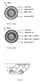
- FIG. 1(A) shows a cross sectional view of an embodiment in this invention.
- a low-frequency electromagnetic induction heater 6 comprising an iron core 1 and an induction coil 2 formed around said iron core 1, and metal pipe 3 formed around said iron core 1 and induction coil 2, wherein a resinous mold 5 is filled out between said induction coil 2 and said surrounding metal pipe 3 so that any substantial gap (vacancy) between a surface of induction coil 2 and a surface of metal pipe 3 in cross sectional view of said metal pipe 3 is excluded.
- FIG.1 (B) shows a cross sectional view of an embodiment in this invention.
- a low-frequency electromagnetic induction heater 6 comprising an iron core 1 and an induction coil 2 formed around said iron core 1, and metal pipes 3 and 4 formed around said iron core 1 and induction coil 2, wherein a resinous mold 5 is filled out between said induction coil 2 and said surrounding metal pipe 3 so that any substantial gap (vacancy) between a surface of induction coil 2 and a surface of metal pipe 4 in cross sectional view of said metal pipes 3 and 4 is excluded.
- the first special feature of the present invention to be described is that a resinous mold 5 is filled out between an induction coil 2 and a surrounding metal pipe 3. Presence of the resinous mold 5 markedly increases an efficiency of heating. Taking an example where water is going to be boiled, temperature of the incide of an induction coil reaches about 500 °C in the absence of the resinous mold, whereas in the presence of the resinous mold the temperature only reaches about 130 °C. Therefore, the presence of the resinous mold serves an important role in maintaining the small temperature difference between a heating element and a material to be heated.
- the second special feature of the present invention to be described is that any substantial gap (vacancy) between a surface of induction coil 2 and a surface of metal pipe 4 is excluded.
- any substantial gap (vacancy) between a pipe 3 and a pipe 4 is excluded. Exclusion of any vacancy or space is effective to improve thermal conduction, therefore, a thermal efficiency.
- Resins used as a resinous mold in the above description are any resins which can be molded. For examples, epoxy resins, acrylic resins, vinyl resins, phenol resins, silicone resins, polyester resins, and so on. More preferable resins are those of thermosetting resins having thermal resistivities above 100 °C.
- the molding or casting methods may be any method known so far, for examples a vacuum casting, conpression casting, and flow-in casting.
- Resinous mold should be
- the heater 6 as the embodiment described above consisting of an iron core, an induction coil, and a metal pipe may be of a vertical or horizontal type.
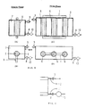
- FIG. 2 A shows a principle of transformer.
- 10 A of an alternating current flows through the primary induction coil of 100 turns by supplying 100 V of a commercial frequency alternating power source at 50 Hz or of 60 Hz
- 10 A of an alternating induction current in 100 V at 50 Hz or of 60 Hz flows through the secondary induction coil of 100 turns in the opposit direction.
- FIG. 2B where the number of turns of the secondary induction coil is just 1, an alternating current flow of 10 A induces flow of 1000 A of an alternating induction current in just 1 V at 50 Hz or of 60 Hz through the secondary induction coil.
- this low voltage and high current performance transformer principle is fully and effectively utillized by employing an induction coil in the primary side and a metal pipe in the secondary side.
- Any electro-conductive metal pipe can be used as a metal pipe in the secondary side in this invention.
- it can be cupreous or iron.
- an induction current which flows through a metal pipe is very high, and this high current is very effective in heating. That is, flow of a high alternating current induces evolution of joule heat by a short-circuit current, and this mechanism of heat evolution is very efficient as is generally anticipated.
- a high voltage is not effective and not necessary in heating. Therefore, it should be enphasized that the important point in this invention is that a high current which is truly effective in heating is specifically utillized instead of high voltage.
- the voltage of the current passing through the secondary cupreous pipe is so low as a user never receives an electrical shock even he touches the pipe, it is very safe.
- the heating area is necessarily very wide because of an employment of specific configuration in which a metal pipe is constructed in the outside of an induction coil. And yet, electric power par unit area of the heating pipe can be higher than the existing heaters.
- the heater in the present invention can be well operated with a supplied electric power higher than 3 W/cm2 or 4 W/cm2 which usually can not be applied to the existing heaters.
- the reason why such high electric power can be supplid specifically to the heater in the present invention is that because the heating area is so wide, the temperature difference ⁇ t between the heater and the material to be heated can be maintaind to be small.
- FIG. 3 shows a model mode of the heating part in this invention.
- the heating part comprises an iron core 1 and an induction coil 2 formed around the iron core, and a metal pipe ( a heating pipe ) formed around these.
- a metal pipe 3 evolves heat. The heat thus evolved is, then, transferred from the metal pipe to a material, for example water, to be heated existing in the outside of the metal pipe. The material is heated up in this manner.
- the metal pipe shown in FIG. 1(B) composes of two combined metal pipes 3 and 4, however, the usable pipe in the pesent invention is not ristricted to the above embodiment.
- a metal pipe shown in FIG. 1(A) of single metal component for examples, a pipe made from stainless steel, or from copper
- a combined pipe composed of more than two metal pipes which is made so as not to have any vacancy in between these pipes, can be used in the present invention.
- An example of a combined pipe is the one having a cupreous pipe as an inside pipe 3 and a stainless steel pipe as an out side pipe 4.
- the copper inside pipe is used in order to improve the heat conduction, and the stainless steel outside pipe is used to have a high stability and a high corrosion resistivity.
- a type of a metal pipe can be chosen and used on the individual occasions or purposes.
- any known method for examples, an explosion-adhesion method or inside pipe enlargement method, can be used.
- a metal pipe may be coated with a resin ( a resinous lining ).
- a resin for example, a metal pipe of a plain copper pipe whose surface is covered with a fluorine-contained polymer (for example, " Teflon (Resistered)" made by E.I.DU PONT DE NEMOURS & COMPANY (INC.)) lining can be usefully employed.
- a low-frequency alternating current power in a commercial frequency range is supplied to the heaters in this invention.
- the reason why the low-frequency commercial current source is used is that the source is widely available and, therefore, economically most preferable.
- FIG. 4 shows a concrete example comprising number of heating metal pipes from one to six and an inputting electric power source of the voltage from 100 to 440 V in 50/60 Hz.
- FIG. 4(A) shows an example connection diagram for the case where a single-phase electric power source is supplied and the number of metal pipe is just one.
- FIG. 4(B) shows an another example connection diagram for the case where a single-phase electric power source is supplied and the number of metal pipe is two.
- FIG. 4 from (C) to (E) show example connection diagrams for the case where a three-phase electric power source is supplied.
- Other electrical connection can be, indeed, usable if it meets with the scope of the present invention.
- Preferable diameter of the metal pipe in the present invention ranges from 70 to 200 mm. If the diameter is too small, then a magnetic flux passes through not only the inside but also the outside of the pipe. This makes the loss of magnetic flux large, therefore, it should be avoided.
- a preferable electric power capacity ranges from 1 to 50 kw, but it is not restricted within this range.
- a preferable length of the metal pipe ranges from 10 cm to 1 m, but it is not restricted within this range.
- FIG. 5(A) shows an example of coil whose coiling density is from the ends to the middle, namely, the middle part is densely coiled and the end parts are roughly coiled.
- This type of coil is very useful in the cases where much of heat release is required or the temperature of the end parts tend to go down by the supply of a material to be heated from the end-side.
- a coil having the dense ceiling in the middle part can be effectively used in the case where the temperature of the middle part has the tendency of go-down by the constitutional reasons.
- 5(B) explains the method effective in improving the temperature inhomogeniety, in which plural kinds of metal is used in a pipe depending on the distance from the end.
- copper is used in the end parts and brass is used in the middle part.
- FIG. 6 shows other embodiments in the present invention.
- FIG. 6(A) and (B), or (C) and (D) show heaters operating with the single-phase or three-phase electric power sources, respectively.
- a heating element 6 used here is the same one shown in FIG. 1.
- 7 means the heating zone
- 8 an entrance for a fluid (for example, water )
- 9 an exit
- 10 a pump.
- a heater 6 is constructed in a vertical type, but a horizontal type works as well.
- FIG. 7 shows an embodiment which has an upper temperature-sensor 11 at the entrance part of the jacket and a bottom temperature-sensor 12 at the exit part of a fluid.
- the signals obtained by these sensors and the signal concerned with the mass of flow detected by a flow-meter are sent to an electric power controler, as are shown in FIGS. 8 and 9.
- the supplied electric power is regulated with reference to the product of the temperature difference between the entering and the exiting fluid and the mass of fruid flow. That is, the electric power controler calculates the excess or the insufficient amounts of heat in Kcal unit to the setting fluid temperature, and decreases or increases the electric power just by the calculated amount, automatically.
- the calculation circuit can momentarily convert the excess or the insufficient amounts of heat in Kcal unit to in KW unit, and controls the voltage supplied to the primary coil, thus, the accurately temperature controlled fluid can e obtained.
- the signal of the mass flow may be any signal, for examples the rotational frequency of the pump or the flow signal itself in the case flow-meter is used.
- the regulation of the electric power is very accurate and easy, because the supplying electric power in KW unit and the the excess or the insufficient amounts of heat in Kcal unit is in a simple linear relationship.
- the voltage induced in the metal pipe of the present invention ranges from 1 V to 0.3 V, and it is very low, lower than a commercial dry cell of 1.5 V. Thus, a user is very safe.
- the heater can be used even under a high humidity.
- an induction coil can be made of cupper wire, aluminum wire, or any conductive metal wires. The life and the durability of the heater in the present invention are significantly extended by the vacuum injection molding of the resin. Because the area of heat transfer is wide, the temperature of the heating part can be as low as 100 °C or 130 °C in the case of the fluid to be heated is water, precipitation and pile up of calcium, a salt, or a scale are prevented.
- Examples of effective applications of the heater in the present invention are a heater for the oil used in heating foods ( a flyer ), a heater for water used in heating foods ( a steam generator ), a heater for a dish washer which requires a hot water in about 80 °C , a heater for cooking below 100°C ( specifically, it is useful in making cooked foods like NIMONO which requires gentle and prolonged heating ), a heater for an organic solvent in a cleaner, a heater for a bath ( rewarming ), a heater for a gas or heavy oil, a heater in a boiler (particularly for the local heating purpose ), and etc.
- the present heater can be widely usable. Because the present heater has the great merits that it is highly safe and its thermal efficiency is very high.
- An electromagnetic induction heater whose cross sectional view is shown in FIG. 1(B) is constructed, as shown in FIGS. 6(A) and 6(B), and 7.
- An iron core is a multi-layered silicon steel plates, an induction coil is made from copper wire, a metal pipe is a combined type having a copper pipe inside and a stainless pipe outside. Any vacancy or space is excluded between the induction coil and the pipe by fulfilling an epoxy resin through a vacuum injection molding.
- the heater is used in heating 1,1,1-trichloroethane solvent in the IC ( integrated circuit; IC chip ) cleaner.
- the heater in the present invention can be operated with the electric powers of 10 KW at the initial stage and of 4 KW at the stationary working stage, whereas the usual type of cleaner with an electric resistance heater requires the electric power of 20 KW at the initial stage and of 10 to 12 KW at the stationary working stage. Also turned out is that precipitation of scales and dust onto a heating pipe is considerably suppressed and the life of heater is prolonged, because the present heater works at relatively low temperature compared with that for the conventional heaters.
- An electromagnetic induction water heater comprising a heater shown in FIG. 1(A) is constructed, as shown in FIGS. 6(C) and 6(D), and 7.
- Three coppers pipes whose diameter is 90mm and the length is 260 mm are placed in a bath. Any vacancy or space is excluded between the induction coil and the pipe by fulfilling an epoxy resin through a vacuum injection molding.
- the supplied electric power par unit area of the heating pipe has been controlled to be 4.5 W, that is, the power density is 4.5 W/ cm2. Water is steadily flowed through the bath with the water flow rate of 15 liters/min.
- the electric power source is the three-phase alternating current source of 200 V, 25 A, in 60 Hz. It is recognized that the present water heater can continuously supply hot water of the well regulated temperature within 80 ⁇ 1 °C.
- the voltage and the current induced in the secondary copper pipes have been measured during the operation, these out to be 0.5 V and about 10000 A, respectively.
- An electromagnetic induction water heater comprising a heater shown in FIG. 1(A) is constructed, as shown in FIGS. 6(C) and 6(D), and 8 and 9.
- Three of copper pipes whose diameter is 90mm and the length is 260 mm are placed in a bath. Any vacancy or space is excluded between the induction coil and the pipe by fulfilling an epoxy resin through a vacuum injection molding.
- the supplied electric power per unit area of the heating pipe has been controlled to be 3.0 W, that is, the power density is 3.0 W/ cm2. Water is steadily flowed through the bath with the water flow rate of 20 liters/min.
- the electric power source is the three-phase alternating current source of 200 V, 25 A, in 60 Hz.
- the temperature of the outcoming hot water and the flow rate of water have been set to be 65 ⁇ 1 °C and 20 liters/min., respectively.
- the hot water of the setting temperature has been obtained with this apparatus irrespective of the fluctuations of the temperature of the water in feed and the mass of water flow, during the long operational period.
- the heater is very easy for cleaning because of its simple inside structure of the bath.
- the voltage and the current induced in the secondary copper pipe have been measured during the operation, these turned out to be 0.5 V and about 10000 A, respectively.
Landscapes
- Physics & Mathematics (AREA)
- Electromagnetism (AREA)
- General Induction Heating (AREA)
- Heat Treatment Of Articles (AREA)
Applications Claiming Priority (2)
| Application Number | Priority Date | Filing Date | Title |
|---|---|---|---|
| JP3753689 | 1989-02-17 | ||
| JP37536/89 | 1989-02-17 |
Publications (3)
| Publication Number | Publication Date |
|---|---|
| EP0383272A2 true EP0383272A2 (fr) | 1990-08-22 |
| EP0383272A3 EP0383272A3 (fr) | 1991-03-27 |
| EP0383272B1 EP0383272B1 (fr) | 1993-07-21 |
Family
ID=12500246
Family Applications (1)
| Application Number | Title | Priority Date | Filing Date |
|---|---|---|---|
| EP90102819A Expired - Lifetime EP0383272B1 (fr) | 1989-02-17 | 1990-02-13 | Elément de chauffage à induction à basse fréquence |
Country Status (5)
| Country | Link |
|---|---|
| US (1) | US5061835A (fr) |
| EP (1) | EP0383272B1 (fr) |
| AU (1) | AU624476B2 (fr) |
| CA (1) | CA2010204C (fr) |
| DE (1) | DE69002252T2 (fr) |
Cited By (4)
| Publication number | Priority date | Publication date | Assignee | Title |
|---|---|---|---|---|
| EP0516881A1 (fr) * | 1991-06-05 | 1992-12-09 | Hidec Corporation Ltd. | Appareil de chauffage à induction basse-fréquence |
| EP1126747A2 (fr) * | 2000-02-19 | 2001-08-22 | ALD Vacuum Technologies AG | Dispositif de chauffage d'une pièce en métal |
| WO2003045113A1 (fr) * | 2001-11-18 | 2003-05-30 | Ronghua Wu | Dispositif et procede de chauffage de liquide par induction electromagnetique et court-circuit au moyen d'une energie triphasee de frequence industrielle |
| WO2013063977A1 (fr) * | 2011-11-01 | 2013-05-10 | Wu Ronghua | Dispositif et procédé de chauffage à double induction électromagnétique à fréquence de courant triphasé pour liquide |
Families Citing this family (23)
| Publication number | Priority date | Publication date | Assignee | Title |
|---|---|---|---|---|
| US5300750A (en) * | 1988-03-16 | 1994-04-05 | Metcal, Inc. | Thermal induction heater |
| JPH04230987A (ja) * | 1990-06-18 | 1992-08-19 | Nikko Kk | 電磁誘導加熱器 |
| US5335161A (en) * | 1992-03-30 | 1994-08-02 | Lorad Corporation | High voltage multipliers and filament transformers for portable X-ray inspection units |
| US5329085A (en) * | 1992-08-05 | 1994-07-12 | Metcal, Inc. | Temperature self regulating heaters and soldering irons |
| US5631509A (en) * | 1994-07-27 | 1997-05-20 | General Electric Company | Motor having thermostatically controlled or limited space heater |
| JP3977136B2 (ja) * | 2001-05-22 | 2007-09-19 | キヤノン株式会社 | コイルユニット |
| US6717118B2 (en) | 2001-06-26 | 2004-04-06 | Husky Injection Molding Systems, Ltd | Apparatus for inductive and resistive heating of an object |
| US6781100B2 (en) | 2001-06-26 | 2004-08-24 | Husky Injection Molding Systems, Ltd. | Method for inductive and resistive heating of an object |
| US8522578B2 (en) * | 2005-03-25 | 2013-09-03 | Lg Electronics Inc. | Steam generator , and laundry device and method thereof |
| US7606475B2 (en) * | 2005-06-10 | 2009-10-20 | Steve Novotny | Heat generation system |
| US20080142510A1 (en) * | 2006-12-14 | 2008-06-19 | Itherm Technologies Lp | Heated transfer pipe |
| US20100025391A1 (en) * | 2008-07-31 | 2010-02-04 | Itherm Technologies, L.P. | Composite inductive heating assembly and method of heating and manufacture |
| FR2942301A1 (fr) * | 2009-02-18 | 2010-08-20 | Elka S A | Installation de preparation instantanee d'eau chaude |
| SE534318C2 (sv) * | 2009-11-13 | 2011-07-05 | Pakit Int Trading Co Inc | Massaform innefattande värmeanordning med sintrade halsar |
| TWI540035B (zh) * | 2011-11-10 | 2016-07-01 | 鴻海精密工業股份有限公司 | 模具裝置 |
| KR101434193B1 (ko) * | 2014-07-24 | 2014-08-28 | 권혜진 | 초고효율 유도 온수가열기 |
| US9739501B2 (en) * | 2014-08-22 | 2017-08-22 | Ut-Battelle, Llc | AC induction field heating of graphite foam |
| US9906078B2 (en) | 2014-08-22 | 2018-02-27 | Ut-Battelle, Llc | Infrared signal generation from AC induction field heating of graphite foam |
| CN106468475A (zh) * | 2015-08-19 | 2017-03-01 | 甘秀坚 | 一种缠绕型分体式储水式电磁热水器 |
| US10284021B2 (en) | 2017-08-14 | 2019-05-07 | Ut-Battelle, Llc | Lighting system with induction power supply |
| US11131502B2 (en) | 2017-08-14 | 2021-09-28 | Ut-Battelle, Llc | Heating system with induction power supply and electromagnetic acoustic transducer with induction power supply |
| CN114074394B (zh) * | 2020-08-18 | 2024-04-16 | 苏州亮福电器有限公司 | 一种提升注塑发泡成型塑件表面质量的方法 |
| CN115011817B (zh) * | 2022-06-07 | 2024-01-26 | 中国恩菲工程技术有限公司 | 碳化钛生产设备及方法 |
Citations (1)
| Publication number | Priority date | Publication date | Assignee | Title |
|---|---|---|---|---|
| GB1142132A (en) * | 1965-02-15 | 1969-02-05 | Black Clawson Co | Improvements in or relating to induction heaters |
Family Cites Families (7)
| Publication number | Priority date | Publication date | Assignee | Title |
|---|---|---|---|---|
| US3307007A (en) * | 1962-11-30 | 1967-02-28 | Charles F Schroeder | Electromagnetic heating unit |
| US4089176A (en) * | 1976-01-20 | 1978-05-16 | The Garrett Corporation | Heat storage method and apparatus |
| JPS5852315B2 (ja) * | 1979-02-21 | 1983-11-21 | チッソエンジニアリング株式会社 | 表皮電流加熱パイプライン |
| JPS5686789A (en) * | 1979-12-18 | 1981-07-14 | Ricoh Co Ltd | Ink jet recording method |
| JPS5839525A (ja) * | 1981-09-03 | 1983-03-08 | Nissan Motor Co Ltd | 動力取出し装置 |
| SE442473B (sv) * | 1981-12-04 | 1985-12-23 | Asea Ab | Induktionsspole |
| CA1266094A (fr) * | 1986-01-17 | 1990-02-20 | Patrick Earl Burke | Systemes de chauffage et de fusion par induction garnis de bobines d'induction perfectionnees |
-
1990
- 1990-02-13 DE DE90102819T patent/DE69002252T2/de not_active Expired - Fee Related
- 1990-02-13 EP EP90102819A patent/EP0383272B1/fr not_active Expired - Lifetime
- 1990-02-14 AU AU49729/90A patent/AU624476B2/en not_active Ceased
- 1990-02-16 US US07/480,489 patent/US5061835A/en not_active Expired - Fee Related
- 1990-02-16 CA CA002010204A patent/CA2010204C/fr not_active Expired - Fee Related
Patent Citations (1)
| Publication number | Priority date | Publication date | Assignee | Title |
|---|---|---|---|---|
| GB1142132A (en) * | 1965-02-15 | 1969-02-05 | Black Clawson Co | Improvements in or relating to induction heaters |
Cited By (9)
| Publication number | Priority date | Publication date | Assignee | Title |
|---|---|---|---|---|
| EP0516881A1 (fr) * | 1991-06-05 | 1992-12-09 | Hidec Corporation Ltd. | Appareil de chauffage à induction basse-fréquence |
| US5270511A (en) * | 1991-06-05 | 1993-12-14 | Nikko Corporation Ltd. | Low-frequency induction heater employing stainless steel material as a secondary winding |
| EP1126747A2 (fr) * | 2000-02-19 | 2001-08-22 | ALD Vacuum Technologies AG | Dispositif de chauffage d'une pièce en métal |
| EP1126747A3 (fr) * | 2000-02-19 | 2003-12-10 | ALD Vacuum Technologies AG | Dispositif de chauffage d'une pièce en métal |
| WO2003045113A1 (fr) * | 2001-11-18 | 2003-05-30 | Ronghua Wu | Dispositif et procede de chauffage de liquide par induction electromagnetique et court-circuit au moyen d'une energie triphasee de frequence industrielle |
| EP1448025A1 (fr) * | 2001-11-18 | 2004-08-18 | Ronghua Wu | Dispositif et procede de chauffage de liquide par induction electromagnetique et court-circuit au moyen d'une energie triphasee de frequence industrielle |
| US7002119B2 (en) | 2001-11-18 | 2006-02-21 | Ronghua Wu | Device for liquid heating by electromagnetic induction and short-circuit using three-phase industrial frequency power |
| EP1448025A4 (fr) * | 2001-11-18 | 2007-06-06 | Ronghua Wu | Dispositif et procede de chauffage de liquide par induction electromagnetique et court-circuit au moyen d'une energie triphasee de frequence industrielle |
| WO2013063977A1 (fr) * | 2011-11-01 | 2013-05-10 | Wu Ronghua | Dispositif et procédé de chauffage à double induction électromagnétique à fréquence de courant triphasé pour liquide |
Also Published As
| Publication number | Publication date |
|---|---|
| CA2010204C (fr) | 1994-03-15 |
| AU4972990A (en) | 1990-08-23 |
| AU624476B2 (en) | 1992-06-11 |
| EP0383272A3 (fr) | 1991-03-27 |
| EP0383272B1 (fr) | 1993-07-21 |
| DE69002252D1 (de) | 1993-08-26 |
| US5061835A (en) | 1991-10-29 |
| DE69002252T2 (de) | 1993-11-04 |
| CA2010204A1 (fr) | 1990-08-17 |
Similar Documents
| Publication | Publication Date | Title |
|---|---|---|
| EP0383272B1 (fr) | Elément de chauffage à induction à basse fréquence | |
| EP0530288B1 (fr) | Appareil servant a rechauffer un fluide | |
| US3777117A (en) | Electric heat generating system | |
| US3975617A (en) | Pipe heating by AC in steel | |
| RU2531292C2 (ru) | Нагревательный кабель с минеральной изоляцией, работающий по принципу скин-эффекта | |
| TWI264239B (en) | Method and apparatus for temperature control of an object | |
| US3440384A (en) | Electromagnetic unit | |
| CN104781616B (zh) | 热水器的感应加热设备及配备有该种设备的热水器 | |
| JP5654791B2 (ja) | 過熱水蒸気生成装置 | |
| US3053959A (en) | Apparatus and method for heating fluids | |
| AU2015278193B2 (en) | Electrode water heater | |
| JPH02297889A (ja) | 低周波電磁誘導加熱器 | |
| WO1995022239A1 (fr) | Element chauffant par induction | |
| US4551613A (en) | Rapid-heating electric water boiler | |
| Curran et al. | Electric-induction fluid heaters | |
| KR102590204B1 (ko) | 수중발열용 유도열히터 | |
| RU2035843C1 (ru) | Электроводонагреватель | |
| RU2074529C1 (ru) | Индукционной нагреватель жидкости | |
| JPH02187561A (ja) | 誘導発熱流体加熱器 | |
| KR102698146B1 (ko) | 유도판에 의한 액체가열용 유도가열기 | |
| RU2759438C1 (ru) | Устройство индукционного нагрева жидкостей проточного типа | |
| RU2053455C1 (ru) | Индукционный электрический нагреватель жидкости | |
| RU2043577C1 (ru) | Индукционный электрокотел в.ф.короля | |
| CN214223421U (zh) | 一种高频电磁热水器 | |
| RU2039327C1 (ru) | Электроотопительный прибор |
Legal Events
| Date | Code | Title | Description |
|---|---|---|---|
| PUAI | Public reference made under article 153(3) epc to a published international application that has entered the european phase |
Free format text: ORIGINAL CODE: 0009012 |
|
| AK | Designated contracting states |
Kind code of ref document: A2 Designated state(s): CH DE FR GB IT LI NL SE |
|
| PUAL | Search report despatched |
Free format text: ORIGINAL CODE: 0009013 |
|
| 17P | Request for examination filed |
Effective date: 19901228 |
|
| AK | Designated contracting states |
Kind code of ref document: A3 Designated state(s): CH DE FR GB IT LI NL SE |
|
| RHK1 | Main classification (correction) |
Ipc: H05B 6/12 |
|
| 17Q | First examination report despatched |
Effective date: 19920914 |
|
| GRAA | (expected) grant |
Free format text: ORIGINAL CODE: 0009210 |
|
| AK | Designated contracting states |
Kind code of ref document: B1 Designated state(s): CH DE FR GB IT LI NL SE |
|
| PG25 | Lapsed in a contracting state [announced via postgrant information from national office to epo] |
Ref country code: IT Free format text: LAPSE BECAUSE OF FAILURE TO SUBMIT A TRANSLATION OF THE DESCRIPTION OR TO PAY THE FEE WITHIN THE PRESCRIBED TIME-LIMIT;WARNING: LAPSES OF ITALIAN PATENTS WITH EFFECTIVE DATE BEFORE 2007 MAY HAVE OCCURRED AT ANY TIME BEFORE 2007. THE CORRECT EFFECTIVE DATE MAY BE DIFFERENT FROM THE ONE RECORDED. Effective date: 19930721 Ref country code: LI Effective date: 19930721 Ref country code: CH Effective date: 19930721 Ref country code: SE Effective date: 19930721 Ref country code: NL Effective date: 19930721 |
|
| REF | Corresponds to: |
Ref document number: 69002252 Country of ref document: DE Date of ref document: 19930826 |
|
| ET | Fr: translation filed | ||
| REG | Reference to a national code |
Ref country code: CH Ref legal event code: PL |
|
| NLV1 | Nl: lapsed or annulled due to failure to fulfill the requirements of art. 29p and 29m of the patents act | ||
| PGFP | Annual fee paid to national office [announced via postgrant information from national office to epo] |
Ref country code: GB Payment date: 19940124 Year of fee payment: 5 |
|
| PGFP | Annual fee paid to national office [announced via postgrant information from national office to epo] |
Ref country code: FR Payment date: 19940214 Year of fee payment: 5 |
|
| PGFP | Annual fee paid to national office [announced via postgrant information from national office to epo] |
Ref country code: DE Payment date: 19940330 Year of fee payment: 5 |
|
| PLBE | No opposition filed within time limit |
Free format text: ORIGINAL CODE: 0009261 |
|
| STAA | Information on the status of an ep patent application or granted ep patent |
Free format text: STATUS: NO OPPOSITION FILED WITHIN TIME LIMIT |
|
| 26N | No opposition filed | ||
| PG25 | Lapsed in a contracting state [announced via postgrant information from national office to epo] |
Ref country code: GB Effective date: 19950213 |
|
| GBPC | Gb: european patent ceased through non-payment of renewal fee |
Effective date: 19950213 |
|
| PG25 | Lapsed in a contracting state [announced via postgrant information from national office to epo] |
Ref country code: FR Effective date: 19951031 |
|
| PG25 | Lapsed in a contracting state [announced via postgrant information from national office to epo] |
Ref country code: DE Effective date: 19951101 |
|
| REG | Reference to a national code |
Ref country code: FR Ref legal event code: ST |