EP0381643A1 - Apparatus for controlling window blinds and awnings - Google Patents
Apparatus for controlling window blinds and awnings Download PDFInfo
- Publication number
- EP0381643A1 EP0381643A1 EP90850014A EP90850014A EP0381643A1 EP 0381643 A1 EP0381643 A1 EP 0381643A1 EP 90850014 A EP90850014 A EP 90850014A EP 90850014 A EP90850014 A EP 90850014A EP 0381643 A1 EP0381643 A1 EP 0381643A1
- Authority
- EP
- European Patent Office
- Prior art keywords
- motor
- blind
- receiving means
- awning
- signal receiving
- Prior art date
- Legal status (The legal status is an assumption and is not a legal conclusion. Google has not performed a legal analysis and makes no representation as to the accuracy of the status listed.)
- Granted
Links
Images
Classifications
-
- E—FIXED CONSTRUCTIONS
- E06—DOORS, WINDOWS, SHUTTERS, OR ROLLER BLINDS IN GENERAL; LADDERS
- E06B—FIXED OR MOVABLE CLOSURES FOR OPENINGS IN BUILDINGS, VEHICLES, FENCES OR LIKE ENCLOSURES IN GENERAL, e.g. DOORS, WINDOWS, BLINDS, GATES
- E06B9/00—Screening or protective devices for wall or similar openings, with or without operating or securing mechanisms; Closures of similar construction
- E06B9/56—Operating, guiding or securing devices or arrangements for roll-type closures; Spring drums; Tape drums; Counterweighting arrangements therefor
- E06B9/80—Safety measures against dropping or unauthorised opening; Braking or immobilising devices; Devices for limiting unrolling
- E06B9/82—Safety measures against dropping or unauthorised opening; Braking or immobilising devices; Devices for limiting unrolling automatic
- E06B9/88—Safety measures against dropping or unauthorised opening; Braking or immobilising devices; Devices for limiting unrolling automatic for limiting unrolling
-
- E—FIXED CONSTRUCTIONS
- E04—BUILDING
- E04F—FINISHING WORK ON BUILDINGS, e.g. STAIRS, FLOORS
- E04F10/00—Sunshades, e.g. Florentine blinds or jalousies; Outside screens; Awnings or baldachins
- E04F10/02—Sunshades, e.g. Florentine blinds or jalousies; Outside screens; Awnings or baldachins of flexible canopy materials, e.g. canvas ; Baldachins
- E04F10/06—Sunshades, e.g. Florentine blinds or jalousies; Outside screens; Awnings or baldachins of flexible canopy materials, e.g. canvas ; Baldachins comprising a roller-blind with means for holding the end away from a building
-
- E—FIXED CONSTRUCTIONS
- E06—DOORS, WINDOWS, SHUTTERS, OR ROLLER BLINDS IN GENERAL; LADDERS
- E06B—FIXED OR MOVABLE CLOSURES FOR OPENINGS IN BUILDINGS, VEHICLES, FENCES OR LIKE ENCLOSURES IN GENERAL, e.g. DOORS, WINDOWS, BLINDS, GATES
- E06B9/00—Screening or protective devices for wall or similar openings, with or without operating or securing mechanisms; Closures of similar construction
- E06B9/56—Operating, guiding or securing devices or arrangements for roll-type closures; Spring drums; Tape drums; Counterweighting arrangements therefor
- E06B9/68—Operating devices or mechanisms, e.g. with electric drive
- E06B2009/6809—Control
- E06B2009/6818—Control using sensors
- E06B2009/6836—Control using sensors sensing obstacle
-
- E—FIXED CONSTRUCTIONS
- E06—DOORS, WINDOWS, SHUTTERS, OR ROLLER BLINDS IN GENERAL; LADDERS
- E06B—FIXED OR MOVABLE CLOSURES FOR OPENINGS IN BUILDINGS, VEHICLES, FENCES OR LIKE ENCLOSURES IN GENERAL, e.g. DOORS, WINDOWS, BLINDS, GATES
- E06B9/00—Screening or protective devices for wall or similar openings, with or without operating or securing mechanisms; Closures of similar construction
- E06B9/56—Operating, guiding or securing devices or arrangements for roll-type closures; Spring drums; Tape drums; Counterweighting arrangements therefor
- E06B9/68—Operating devices or mechanisms, e.g. with electric drive
- E06B2009/6809—Control
- E06B2009/6818—Control using sensors
- E06B2009/6845—Control using sensors sensing position
-
- Y—GENERAL TAGGING OF NEW TECHNOLOGICAL DEVELOPMENTS; GENERAL TAGGING OF CROSS-SECTIONAL TECHNOLOGIES SPANNING OVER SEVERAL SECTIONS OF THE IPC; TECHNICAL SUBJECTS COVERED BY FORMER USPC CROSS-REFERENCE ART COLLECTIONS [XRACs] AND DIGESTS
- Y10—TECHNICAL SUBJECTS COVERED BY FORMER USPC
- Y10S—TECHNICAL SUBJECTS COVERED BY FORMER USPC CROSS-REFERENCE ART COLLECTIONS [XRACs] AND DIGESTS
- Y10S160/00—Flexible or portable closure, partition, or panel
- Y10S160/17—Venetian blinds, motor driven
Definitions
- the invention relates to method and apparatus for controlling window blinds of the venetian type or roller blinds or blinds made of folded material, and to awnings that are placed on the outside of a building.
- Automation for such window blinds is such that the blind can be raised or lowered electrically.
- a small electric motor usually operating through a gearbox, winds up the lifting cord or band of the blind to raise it and winds down the cord or band to lower it.
- a problem that arises is how the electric motor is to be stopped when the blind is fully raised or fully lowered.
- the motor is stopped by microswitches which have been built into the blind, and which open when the blind is fully up or fully down.
- a similar system with microswitches is used to stop the motor of an awning when the awning is fully extended or fully retracted.
- Such systems involve considerable difficulties with installation, are relatively expensive, tend to be unreliability and involve time consuming initial installation.
- the present invention also including a motor overcomes the difficulties mentioned above by using the rotation of the motor rotor for delivering signals to a signal receiving means which in turn delivers signals to stop the motor at the end positions of the blind or awning. Preferably the number of revolutions is counted and the motor is stopped after a fixed number of revolutions has been completed.
- a direct current motor is running there is a small voltage or current pulse every time the sections of the rotor pass through the magnetic field of the field windings.
- These voltage or current pulses can be detected in the cables leading to the motor.
- pulses can be detected by a small coil or sensor attached to the outside of the motor casing.
- a third cable leading from the motor is then normally required.
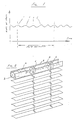
- Fig. 1 the fluctuations in voltage or current 1, that occur when the segments of the rotor pass through the magnetic field of the stator, are shown.
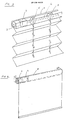
- Fig. 2 is shown the construction of a venetian blind with motor 3, and gearbox 4 in the top rail 2.
- the gearbox drives an axel 6, which turns the hubs 5, upon which the lifting cord or band 7 is wound.
- motor and gearbox turning an axel inside of the top rail and being used to wind up the lifting cords or bands is common to the designs.
- Fig. 3 the construction of a window blind made with folded material is shown.
- This has a top rail 2, with a motor 3, and gearbox 4, which is connected to an axel 6, which turns winding hubs 5, upon which the lifting cords or band 7, are wound.
- motor 3, gearbox 4 which is connected to an axel 6, which turns winding hubs 5, upon which the lifting cords or band 7, are wound.
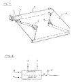
- Fig. 4 the construction of a roller blind is shown. This has a motor 3, and gearbox 4.
- the gearbox causes the tube 8, to rotate, thereby rolling the blind up or allowing it to come down.
- Fig. 5 the construction of an awning is shown. This is similar in design to the roller blind in Fig. 4, however there are spring loaded arms 9, which streach the awning material 10. There is a motor 3, and gearbox 4, which causes the tube 8 to rotate rolling up the awning material 10.
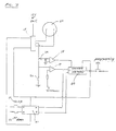
- Fig. 6 illustrates the functions of the digital counter used by the invention.
- the impulses to the counter are fed to the counter via input 12.
- a signal telling the counter if impulses are to be added or subtracted, that is if the blind or awning is being let down or being lifted up is given to the counter via input 11.
- the value on the counter is reset preferably to zero, when at the top position by a signal to input 13.
- the value currently in the counter can be transferred to the memory section by manually closing switch 15 on input 16.
- Fig. 7 illustrates a typical electric circuit that can be used to detect the pulses in the cables leading to the motor and feeding them to the counter unit where they are added or subtracted.
- Unit 17 is a standard integrated circuit which is used to stop and start the motor.
- the connection between unit 17 and earth via resistance 24 causes a fluctuating voltage over resistance 24, which is proportional to the fluctuating motor current.
- This fluctuation voltage is coupled via condensor 25 to an integrated circuit 18 which amplifies the voltage pulses so that they can operate the counter unit 20.
- Amplifier 19 compares the fluctuating voltage at resistance 24 with a reference voltage and when this voltage rises above the reference voltage, as will occur when the motor is nearly stopped then the amplifier sends a signal to the counter resetting it to zero. A signal is sent at the same time to switch 21, which stops the motor. Switches 23 are manually operated switches for raising or lowering the blind or awning.
- the blind is raised to its highest position when the counting apparatus is set to zero.
- the blind is then run to its lowest position when the sum of the pulses due to the motors rotation is stored in a memory. This value is then equivalent to the blinds lowest position.
- the electric current used by the motor is measured and when the blind is fully raised and can go no further the speed of the motor falls and the current to the motor increases rapidly.
- the blind is at its top position.
- the motor is then stopped and at the same time a signal is sent to the digital counting apparatus setting it to zero.
- This method of stopping the blind at its top position is generally preferred. This is because the counting apparatus is zeroed each time the blind is operated and the possibility for wandering of the set top and bottom positions caused, for example, by an accumulation of a small error in the counting of the pulses, is avoided.
- An interesting advantage of the system is that the lifting or lowering of the blind may be stopped in an intermediate position and when the raising or lowering is continued the blind continues to its correct end position. This is because the number of pulses equivalent to the intermediate position is retained in the counter while the blind is stationary and counting continues when the blind moves again.
- the fully rolled up position of the awning corresponds to the top position of the blind and the fully extended position of the awning corresponds to the fully down position of the blind.
- the awning has a direct current motor and gearbox installed in the winding tube which causes the tube to rotate.
- the pulses from the motor as it rotates are fed to a digital counting apparatus and the number of revolutions of the motor thereby known.
- the counting apparatus is zeroed at the fully rolled up position by measuring the current fed to the motor and setting the counter to zero when the current exceeds a set value.
- the awning is then fully extended and the sum of the pulses due to the motors rotation is stored in the memory. This value being used to stop the motor in future operations at the awnings fully extended position.
Abstract
Description
- The invention relates to method and apparatus for controlling window blinds of the venetian type or roller blinds or blinds made of folded material, and to awnings that are placed on the outside of a building.
- Automation for such window blinds is such that the blind can be raised or lowered electrically. A small electric motor usually operating through a gearbox, winds up the lifting cord or band of the blind to raise it and winds down the cord or band to lower it. A problem that arises is how the electric motor is to be stopped when the blind is fully raised or fully lowered. At present the motor is stopped by microswitches which have been built into the blind, and which open when the blind is fully up or fully down. A similar system with microswitches is used to stop the motor of an awning when the awning is fully extended or fully retracted. However such systems involve considerable difficulties with installation, are relatively expensive, tend to be unreliability and involve time consuming initial installation.
- The present invention also including a motor overcomes the difficulties mentioned above by using the rotation of the motor rotor for delivering signals to a signal receiving means which in turn delivers signals to stop the motor at the end positions of the blind or awning. Preferably the number of revolutions is counted and the motor is stopped after a fixed number of revolutions has been completed. When a direct current motor is running there is a small voltage or current pulse every time the sections of the rotor pass through the magnetic field of the field windings. These voltage or current pulses can be detected in the cables leading to the motor. Alternatively pulses can be detected by a small coil or sensor attached to the outside of the motor casing. However a third cable leading from the motor is then normally required.
- The characteristics of the invention appear from the following claims.
- Embodiments of the invention are in the following with reference to the accompanying drawings described more in detail, wherein also further advantages are described.
- Figure 1 shows the voltage being supplied to a direct current motor and pulses arising from the rotation of the rotor.
- Figure 2 shows a venetian blind with the motor and gearbox, and winding reels for the lifting cords or bands.
- Figure 3 shows another type of window blind with a similar winding mechanism.
- Figure 4 shows a roller blind with its system of winding.
- Figure 5 shows an awning with its motor and gearbox, installed in the winding tube.
- Figure 6 illustrates a typical digital counting apparatus and the functions that it has.
- Figure 7 shows an electrical circuit for controlling the motor which includes the digital counting unit.
- In Fig. 1 the fluctuations in voltage or current 1, that occur when the segments of the rotor pass through the magnetic field of the stator, are shown.
- In Fig. 2 is shown the construction of a venetian blind with
motor 3, andgearbox 4 in thetop rail 2. The gearbox drives anaxel 6, which turns thehubs 5, upon which the lifting cord or band 7 is wound. There may be several variations of method of winding up the lifting cord or band, however the use of motor and gearbox turning an axel inside of the top rail and being used to wind up the lifting cords or bands is common to the designs. - In Fig. 3 the construction of a window blind made with folded material is shown. This has a
top rail 2, with amotor 3, andgearbox 4, which is connected to anaxel 6, which turns windinghubs 5, upon which the lifting cords or band 7, are wound. Again there may be a variation in the method of winding up the lifting cords or bands, however the use of motor, gearbox and axel is common to all methods. - In Fig. 4 the construction of a roller blind is shown. This has a
motor 3, andgearbox 4. The gearbox causes thetube 8, to rotate, thereby rolling the blind up or allowing it to come down. - In Fig. 5 the construction of an awning is shown. This is similar in design to the roller blind in Fig. 4, however there are spring loaded
arms 9, which streach theawning material 10. There is amotor 3, andgearbox 4, which causes thetube 8 to rotate rolling up theawning material 10. - Fig. 6 illustrates the functions of the digital counter used by the invention. The impulses to the counter are fed to the counter via
input 12. A signal telling the counter if impulses are to be added or subtracted, that is if the blind or awning is being let down or being lifted up is given to the counter via input 11. The value on the counter is reset preferably to zero, when at the top position by a signal to input 13. When the value in the counter equals the value in the memory section of the unit then a signal is given viaoutput 14. The value currently in the counter can be transferred to the memory section by manually closingswitch 15 oninput 16. There are possible alternative combinations of counter units and separate memory units that can be used to achieve the same operative function as described above. - Fig. 7 illustrates a typical electric circuit that can be used to detect the pulses in the cables leading to the motor and feeding them to the counter unit where they are added or subtracted.
Unit 17 is a standard integrated circuit which is used to stop and start the motor. The connection betweenunit 17 and earth viaresistance 24 causes a fluctuating voltage overresistance 24, which is proportional to the fluctuating motor current. This fluctuation voltage is coupled viacondensor 25 to an integratedcircuit 18 which amplifies the voltage pulses so that they can operate thecounter unit 20. -
Amplifier 19 compares the fluctuating voltage atresistance 24 with a reference voltage and when this voltage rises above the reference voltage, as will occur when the motor is nearly stopped then the amplifier sends a signal to the counter resetting it to zero. A signal is sent at the same time to switch 21, which stops the motor.Switches 23 are manually operated switches for raising or lowering the blind or awning. - For the small motors used in blind automation there will usually be three pulses for each revolution of the rotor. These pulses, or a proportion of them, are fed to the digital counting apparatus. The pulses are then used to control the blind motor in the following way:
- The blind is raised to its highest position when the counting apparatus is set to zero.
- The blind is then run to its lowest position when the sum of the pulses due to the motors rotation is stored in a memory. This value is then equivalent to the blinds lowest position.
- After this the counter operates in the following way:
- When the blind is lowered the pulses due to the motors rotation are summed up and when the number reaches the number stored in the memory the motor is stopped - the blind having reached its lowest or bottom position.
- When the blind is raised the pulses due to motors rotation are subtracted and when the number of pulses recorded by the counter reaches zero the motor is stopped - the blind having reached its highest or top position.
- It can be added that is has been found useful to have another system to check that the blind has reached its top position and not just to rely solely on the pulse counter being zero.
- The electric current used by the motor is measured and when the blind is fully raised and can go no further the speed of the motor falls and the current to the motor increases rapidly. When the current has increased over a predetermined value then the blind is at its top position. The motor is then stopped and at the same time a signal is sent to the digital counting apparatus setting it to zero. This method of stopping the blind at its top position is generally preferred. This is because the counting apparatus is zeroed each time the blind is operated and the possibility for wandering of the set top and bottom positions caused, for example, by an accumulation of a small error in the counting of the pulses, is avoided. An additional advantage of zeroing the top position of the blind each time it is raised is that if the lifting cords or bands should streatch with time because of sunshine or because of heat or cold then there is an automatic compensation for this because the blind is always raised to its top position and then lowered a fixed distance, i.e. lowered a fixed number of revolutions of the winding axel or winding reel.
- An interesting advantage of the system is that the lifting or lowering of the blind may be stopped in an intermediate position and when the raising or lowering is continued the blind continues to its correct end position. This is because the number of pulses equivalent to the intermediate position is retained in the counter while the blind is stationary and counting continues when the blind moves again.
- If the system is used to control an awning instead of a blind then the fully rolled up position of the awning corresponds to the top position of the blind and the fully extended position of the awning corresponds to the fully down position of the blind. The awning has a direct current motor and gearbox installed in the winding tube which causes the tube to rotate. The pulses from the motor as it rotates are fed to a digital counting apparatus and the number of revolutions of the motor thereby known. The counting apparatus is zeroed at the fully rolled up position by measuring the current fed to the motor and setting the counter to zero when the current exceeds a set value. The awning is then fully extended and the sum of the pulses due to the motors rotation is stored in the memory. This value being used to stop the motor in future operations at the awnings fully extended position.
Claims (10)
Applications Claiming Priority (2)
| Application Number | Priority Date | Filing Date | Title |
|---|---|---|---|
| SE8900216 | 1989-01-20 | ||
| SE8900216A SE500651C2 (en) | 1989-01-20 | 1989-01-20 | Device for controlling the drive motor of window blinds or awnings |
Publications (2)
| Publication Number | Publication Date |
|---|---|
| EP0381643A1 true EP0381643A1 (en) | 1990-08-08 |
| EP0381643B1 EP0381643B1 (en) | 1993-04-21 |
Family
ID=20374821
Family Applications (1)
| Application Number | Title | Priority Date | Filing Date |
|---|---|---|---|
| EP90850014A Expired - Lifetime EP0381643B1 (en) | 1989-01-20 | 1990-01-15 | Apparatus for controlling window blinds and awnings |
Country Status (4)
| Country | Link |
|---|---|
| US (1) | US5038087A (en) |
| EP (1) | EP0381643B1 (en) |
| DE (1) | DE69001362T2 (en) |
| SE (1) | SE500651C2 (en) |
Cited By (23)
| Publication number | Priority date | Publication date | Assignee | Title |
|---|---|---|---|---|
| WO1992000557A1 (en) * | 1990-06-27 | 1992-01-09 | Presto Gebr. Vedder Gmbh | Roller blind control |
| EP0485747A1 (en) * | 1990-10-17 | 1992-05-20 | Baumann AG Rolladenfabrik | Drive unit for a shutter as well as shutter with such a drive unit |
| FR2673234A1 (en) * | 1991-02-26 | 1992-08-28 | Kraemer Thierry | Device for monitoring the operation of automatic doors |
| WO1995009961A1 (en) * | 1993-10-06 | 1995-04-13 | Gerhard Geiger Gmbh & Co. | Adjusting device for awnings or roller shutters |
| EP0678649A1 (en) * | 1993-04-21 | 1995-10-25 | EFAFLEX Transport- und Lagertechnik GmbH | Roller shutter with controlling device |
| DE19519183A1 (en) * | 1994-10-05 | 1996-04-11 | Marantec Antrieb Steuerung | Control for driving an object that can be moved back and forth between two end positions |
| EP0750092A1 (en) * | 1995-06-21 | 1996-12-27 | Somfy | Roll-up device for venetian blinds |
| DE19523241A1 (en) * | 1995-06-27 | 1997-01-02 | Aumueller Aumatic Gmbh | Method of monitoring , controlling or regulating electrical actuator drives e.g. for doors, gates, windows or light fittings |
| FR2740824A1 (en) * | 1995-11-07 | 1997-05-09 | Somfy | Electrical motor actuated rolling shutter |
| EP0793077A2 (en) * | 1996-02-29 | 1997-09-03 | Lucas Industries Inc. | Position dectector circuit for an electric motor |
| EP0770757A3 (en) * | 1995-10-28 | 1998-12-16 | elero GmbH | Method of actuating awnings or the like by an electric motor |
| DE29716482U1 (en) * | 1997-09-13 | 1999-01-14 | Hoermann Kg Antriebstechnik | Movement distance detection device for the control of an object driven by an electric motor |
| EP0940554A1 (en) * | 1998-03-06 | 1999-09-08 | Hans Arnhold | Roller shutter control device |
| US6069465A (en) * | 1997-10-31 | 2000-05-30 | Hunter Douglas International N.V. | Group control system for light regulating devices |
| EP1188896A3 (en) * | 2000-09-18 | 2003-09-17 | Jolly Motor International S.p.A. | Remote control for venetian blinds |
| EP1359285A1 (en) * | 1998-03-06 | 2003-11-05 | Hans Arnhold | Roller shutter control device |
| EP1333150A3 (en) * | 2002-02-01 | 2004-02-04 | Somfy | Motorized window covering and method for controlling the position of a motorized window covering |
| US6794778B1 (en) | 2003-05-23 | 2004-09-21 | Harmonic Design, Inc. | Braking system for powered window covering |
| US6924615B2 (en) | 2002-02-01 | 2005-08-02 | Somfy Sas | Magnetic encoder for powered window covering |
| US6967418B2 (en) | 2003-05-23 | 2005-11-22 | Somfy Sas | Magnetic brake for powered window covering |
| US7002310B2 (en) | 2004-02-25 | 2006-02-21 | Somfy Sas | Piezo-based encoder with magnetic brake for powered window covering |
| FR2880740A1 (en) * | 2005-01-11 | 2006-07-14 | Somfy Sas | DIRECT CURRENT MOTOR ACTUATOR WITH IRREVERSIBLE TRANSMISSION FOR MANUFACTURING A SHUTTER |
| US7259485B2 (en) | 2003-05-23 | 2007-08-21 | Somfy Sas | Magnetic brake for window covering powered by DC motor |
Families Citing this family (51)
| Publication number | Priority date | Publication date | Assignee | Title |
|---|---|---|---|---|
| DE4009373A1 (en) * | 1990-03-23 | 1991-09-26 | Somfy Feinmech & Elektrotech | METHOD AND DEVICE FOR POSITION CONTROL AND MONITORING OF AN AWNING OR THE LIKE |
| US6404158B1 (en) | 1992-04-22 | 2002-06-11 | Nartron Corporation | Collision monitoring system |
| US7579802B2 (en) * | 1992-04-22 | 2009-08-25 | Nartron Corporation | Collision monitoring system |
| US7548037B2 (en) * | 1992-04-22 | 2009-06-16 | Nartron Corporation | Collision monitoring system |
| US6064165A (en) * | 1992-04-22 | 2000-05-16 | Nartron Corporation | Power window or panel controller |
| US5952801A (en) * | 1992-04-22 | 1999-09-14 | Nartron Corporation | Power window or panel controller |
| US5270629A (en) * | 1992-04-30 | 1993-12-14 | Casper Shih | Automatic vertical blind controller with memory |
| JP2715227B2 (en) * | 1992-10-09 | 1998-02-18 | 株式会社三協精機製作所 | Stop detection method for refrigerator damper |
| US5495153A (en) * | 1993-06-11 | 1996-02-27 | Harmonic Design, Inc. | Head rail-mounted mini-blind actuator for vertical blinds and pleated shades |
| US5698958A (en) * | 1993-06-11 | 1997-12-16 | Harmonic Design, Inc. | Head rail-mounted actuator for window coverings |
| US6060852A (en) * | 1993-06-11 | 2000-05-09 | Harmonic Design, Inc. | Head rail-mounted actuator for window covering |
| US5444339A (en) * | 1993-06-11 | 1995-08-22 | Harmonic Design, Inc. | Mini-blind actuator |
| US5436539A (en) * | 1993-08-30 | 1995-07-25 | United Technologies Automotive, Inc. | Adaptive window lift control with pinch force based on object rigidity and window position |
| US5483135A (en) * | 1994-06-06 | 1996-01-09 | Ford Motor Company | Adaptive system and method for controlling vehicle window operation |
| US5760558A (en) * | 1995-07-24 | 1998-06-02 | Popat; Pradeep P. | Solar-powered, wireless, retrofittable, automatic controller for venetian blinds and similar window converings |
| DE19527456B4 (en) * | 1995-07-27 | 2004-12-09 | Robert Bosch Gmbh | Method of positioning a part |
| US5793174A (en) * | 1996-09-06 | 1998-08-11 | Hunter Douglas Inc. | Electrically powered window covering assembly |
| US6369530B2 (en) | 1996-09-06 | 2002-04-09 | Hunter Douglas Inc. | Battery-powered wireless remote-control motorized window covering assembly having controller components |
| FR2754117B1 (en) * | 1996-09-30 | 1998-11-27 | Somfy | CONTROL DEVICE FOR AN ASYNCHRONOUS BLIND MOTOR OR ROLLER SHUTTER |
| US5848634A (en) * | 1996-12-27 | 1998-12-15 | Latron Electronics Co. Inc. | Motorized window shade system |
| TW392783U (en) * | 1998-08-27 | 2000-06-01 | Hu Yu Min | Electric curtain with learning ability |
| US6446693B1 (en) * | 1999-01-11 | 2002-09-10 | Hunter Douglas Inc. | Headrail and control system for powered coverings for architectural openings |
| US6198243B1 (en) * | 1999-02-23 | 2001-03-06 | Johnson Controls Technology Co. | Method for automatically determining range of movement of an electromechanical actuator |
| US6246194B1 (en) * | 1999-09-07 | 2001-06-12 | Meritor Light Vehicle Systems, Inc. | Method and system for detecting an object in an automotive window |
| FR2833296B1 (en) * | 2001-12-07 | 2004-07-02 | Bernard Simon | SYSTEM FOR IMMOBILIZING A REINFORCEMENT TUBE IN A FLEXIBLE APRON OF A HANDLING DOOR |
| US20030145956A1 (en) * | 2002-02-01 | 2003-08-07 | Domel Douglas R. | Operating signal system and method for controlling a motorized window covering |
| FR2899923B1 (en) * | 2006-04-14 | 2009-02-06 | Somfy Sas | METHOD FOR CONTROLLING AND INSTALLING A STORE CONTROLLED THEREBY |
| KR20040049500A (en) * | 2002-12-06 | 2004-06-12 | 박선은 | Auto blinder type display assembly |
| JP4036745B2 (en) * | 2002-12-25 | 2008-01-23 | ミネベア株式会社 | Hoisting device |
| US6782936B1 (en) * | 2003-02-14 | 2004-08-31 | Girard Systems, Inc. | Awning system for a recreational vehicle |
| US20050072532A1 (en) * | 2003-10-01 | 2005-04-07 | Toby Holden | Self-powered motorized window awning |
| EP1520665A1 (en) * | 2003-10-02 | 2005-04-06 | S.A. Jac N.V. | Automatic bread slicing machine |
| US7091682B2 (en) * | 2004-10-26 | 2006-08-15 | Harmonic Design, Inc. | Frequency stabilizer circuit for window covering control chip clock |
| US7242162B2 (en) * | 2004-11-22 | 2007-07-10 | Carefree/Scott Fetzer Company | Apparatus and method for retracting awning |
| FR2880125B1 (en) * | 2004-12-24 | 2007-03-30 | Siminor Technologies Castres S | METHOD FOR DETERMINING THE POSITION OF THE SHAFT OF A DRIVE MOTOR OF A SHUTTER AND ACTUATOR FOR ITS IMPLEMENTATION |
| US20060162877A1 (en) * | 2005-01-24 | 2006-07-27 | Jame-San Chou | Automatic remote-controlled curtain |
| FR2910506B1 (en) * | 2006-12-26 | 2009-02-27 | Somfy Sas | METHOD OF ADJUSTING A SAFETY THRESHOLD BEYOND WHICH A STORE MUST BE WRAPPED |
| US20080262637A1 (en) * | 2007-04-20 | 2008-10-23 | David M. Dorrough | Control for a motorized blind |
| US20110017411A1 (en) * | 2009-07-22 | 2011-01-27 | Bin Terng Enterprise Co., Ltd. | Electric curtain via accurately controlling a stop position of its covering sheet |
| US8659246B2 (en) | 2010-02-23 | 2014-02-25 | Homerun Holdings Corporation | High efficiency roller shade |
| US8575872B2 (en) | 2010-02-23 | 2013-11-05 | Homerun Holdings Corporation | High efficiency roller shade and method for setting artificial stops |
| US9249623B2 (en) | 2010-02-23 | 2016-02-02 | Qmotion Incorporated | Low-power architectural covering |
| US9194179B2 (en) | 2010-02-23 | 2015-11-24 | Qmotion Incorporated | Motorized shade with the transmission wire passing through the support shaft |
| US8939190B2 (en) * | 2010-10-18 | 2015-01-27 | QMotion Limited | Motorizable tilt shade system and method |
| US8820388B2 (en) * | 2010-10-18 | 2014-09-02 | Qmotion Incorporated | Motorizable shade system and method |
| US9091115B2 (en) | 2010-10-18 | 2015-07-28 | Qmotion Incorporated | Motorizable tilt shade system and method |
| CN104181932B (en) * | 2013-05-21 | 2017-09-22 | 台达电子工业股份有限公司 | Stopping means and control method |
| CA2932784C (en) * | 2015-06-11 | 2021-11-02 | Composite Solutions, Inc. | Retractable awning and window frame assembly |
| JP6704776B2 (en) * | 2016-04-04 | 2020-06-03 | トーソー株式会社 | Height setting device for the lower end of the shield of the electric solar shading device |
| GB2559045A (en) * | 2016-12-22 | 2018-07-25 | Stanley Gunton Bruce | Shutter control |
| US11097901B2 (en) * | 2017-05-19 | 2021-08-24 | Span Tech Llc | Adjustable conveyor belt guiderail and related methods |
Citations (3)
| Publication number | Priority date | Publication date | Assignee | Title |
|---|---|---|---|---|
| FR2557397A1 (en) * | 1983-12-21 | 1985-06-28 | Kunz Kurt | Motor control device for foil dispenser |
| DE3425874A1 (en) * | 1984-07-13 | 1986-01-16 | Richard 5030 Hürth Greis | Control device for the electric-motor drive of roller shutters, louvres and the like |
| DE3526140A1 (en) * | 1985-07-22 | 1987-01-29 | Sm Ind Co | Roller blind winding device |
Family Cites Families (8)
| Publication number | Priority date | Publication date | Assignee | Title |
|---|---|---|---|---|
| GB2013428A (en) * | 1978-01-25 | 1979-08-08 | Tekron Patents Ltd | Circuits for electric window winders for vehicles |
| JPS5671482A (en) * | 1979-11-15 | 1981-06-15 | Secoh Giken Inc | Motor having preferable stopping property |
| US4443745A (en) * | 1980-09-12 | 1984-04-17 | Tokyo Shibaura Denki Kabushiki Kaisha | Rotation signal detection device of DC motor with brushes |
| DE3226614A1 (en) * | 1982-07-16 | 1984-01-19 | Robert Bosch Gmbh, 7000 Stuttgart | CIRCUIT ARRANGEMENT FOR INPUTING AND EXTENDING A MOTOR-DRIVEN ANTENNA |
| DE3305725A1 (en) * | 1983-02-18 | 1984-08-23 | Bayerische Motoren Werke AG, 8000 München | DRIVE DEVICE FOR A FLAP IN MOTOR VEHICLES |
| JPS6139873A (en) * | 1984-07-30 | 1986-02-26 | Alps Electric Co Ltd | Automatic window glass elevating device |
| GB2198860B (en) * | 1986-10-03 | 1990-12-12 | Jidosha Denki Kogyo Kk | An automatic opening and closing device for a window |
| US4902953A (en) * | 1988-08-19 | 1990-02-20 | Kraft David W | Motorized window blind electrical actuator |
-
1989
- 1989-01-20 SE SE8900216A patent/SE500651C2/en unknown
-
1990
- 1990-01-15 DE DE90850014T patent/DE69001362T2/en not_active Expired - Fee Related
- 1990-01-15 EP EP90850014A patent/EP0381643B1/en not_active Expired - Lifetime
- 1990-01-17 US US07/466,563 patent/US5038087A/en not_active Expired - Fee Related
Patent Citations (3)
| Publication number | Priority date | Publication date | Assignee | Title |
|---|---|---|---|---|
| FR2557397A1 (en) * | 1983-12-21 | 1985-06-28 | Kunz Kurt | Motor control device for foil dispenser |
| DE3425874A1 (en) * | 1984-07-13 | 1986-01-16 | Richard 5030 Hürth Greis | Control device for the electric-motor drive of roller shutters, louvres and the like |
| DE3526140A1 (en) * | 1985-07-22 | 1987-01-29 | Sm Ind Co | Roller blind winding device |
Cited By (31)
| Publication number | Priority date | Publication date | Assignee | Title |
|---|---|---|---|---|
| WO1992000557A1 (en) * | 1990-06-27 | 1992-01-09 | Presto Gebr. Vedder Gmbh | Roller blind control |
| EP0485747A1 (en) * | 1990-10-17 | 1992-05-20 | Baumann AG Rolladenfabrik | Drive unit for a shutter as well as shutter with such a drive unit |
| FR2673234A1 (en) * | 1991-02-26 | 1992-08-28 | Kraemer Thierry | Device for monitoring the operation of automatic doors |
| EP0678649A1 (en) * | 1993-04-21 | 1995-10-25 | EFAFLEX Transport- und Lagertechnik GmbH | Roller shutter with controlling device |
| WO1995009961A1 (en) * | 1993-10-06 | 1995-04-13 | Gerhard Geiger Gmbh & Co. | Adjusting device for awnings or roller shutters |
| DE19519183A1 (en) * | 1994-10-05 | 1996-04-11 | Marantec Antrieb Steuerung | Control for driving an object that can be moved back and forth between two end positions |
| EP0750092A1 (en) * | 1995-06-21 | 1996-12-27 | Somfy | Roll-up device for venetian blinds |
| FR2735812A1 (en) * | 1995-06-21 | 1996-12-27 | Somfy | MOTORIZED WINDING DEVICE FOR VENETIAN BLINDS |
| US5699847A (en) * | 1995-06-21 | 1997-12-23 | Somfy | Motorized roll-up device for venetian blinds |
| DE19523241A1 (en) * | 1995-06-27 | 1997-01-02 | Aumueller Aumatic Gmbh | Method of monitoring , controlling or regulating electrical actuator drives e.g. for doors, gates, windows or light fittings |
| EP0770757A3 (en) * | 1995-10-28 | 1998-12-16 | elero GmbH | Method of actuating awnings or the like by an electric motor |
| FR2740824A1 (en) * | 1995-11-07 | 1997-05-09 | Somfy | Electrical motor actuated rolling shutter |
| EP0793077A2 (en) * | 1996-02-29 | 1997-09-03 | Lucas Industries Inc. | Position dectector circuit for an electric motor |
| EP0793077A3 (en) * | 1996-02-29 | 1998-05-13 | Lucas Industries Inc. | Position dectector circuit for an electric motor |
| DE29716482U1 (en) * | 1997-09-13 | 1999-01-14 | Hoermann Kg Antriebstechnik | Movement distance detection device for the control of an object driven by an electric motor |
| US6069465A (en) * | 1997-10-31 | 2000-05-30 | Hunter Douglas International N.V. | Group control system for light regulating devices |
| EP0940554A1 (en) * | 1998-03-06 | 1999-09-08 | Hans Arnhold | Roller shutter control device |
| EP1359285A1 (en) * | 1998-03-06 | 2003-11-05 | Hans Arnhold | Roller shutter control device |
| EP1359286A1 (en) * | 1998-03-06 | 2003-11-05 | Hans Arnhold | Roller shutter control device |
| EP1359284A1 (en) * | 1998-03-06 | 2003-11-05 | Hans Arnhold | Roller shutter control device |
| EP1188896A3 (en) * | 2000-09-18 | 2003-09-17 | Jolly Motor International S.p.A. | Remote control for venetian blinds |
| US6870338B2 (en) | 2002-02-01 | 2005-03-22 | Harmonic Design, Inc. | Magnetic encoder for powered window covering |
| EP1333150A3 (en) * | 2002-02-01 | 2004-02-04 | Somfy | Motorized window covering and method for controlling the position of a motorized window covering |
| US6924615B2 (en) | 2002-02-01 | 2005-08-02 | Somfy Sas | Magnetic encoder for powered window covering |
| US6794778B1 (en) | 2003-05-23 | 2004-09-21 | Harmonic Design, Inc. | Braking system for powered window covering |
| US6967418B2 (en) | 2003-05-23 | 2005-11-22 | Somfy Sas | Magnetic brake for powered window covering |
| US7259485B2 (en) | 2003-05-23 | 2007-08-21 | Somfy Sas | Magnetic brake for window covering powered by DC motor |
| US7002310B2 (en) | 2004-02-25 | 2006-02-21 | Somfy Sas | Piezo-based encoder with magnetic brake for powered window covering |
| FR2880740A1 (en) * | 2005-01-11 | 2006-07-14 | Somfy Sas | DIRECT CURRENT MOTOR ACTUATOR WITH IRREVERSIBLE TRANSMISSION FOR MANUFACTURING A SHUTTER |
| WO2006075222A1 (en) * | 2005-01-11 | 2006-07-20 | Somfy Sas | Actuator comprising a direct-current motor and an irreversible transmission device, which is used to manoeuvre a roller shutter |
| US7564203B2 (en) | 2005-01-11 | 2009-07-21 | Somfy Sas | Actuator with DC motor and with irreversible transmission for maneuvering a roller blind |
Also Published As
| Publication number | Publication date |
|---|---|
| US5038087A (en) | 1991-08-06 |
| DE69001362D1 (en) | 1993-05-27 |
| EP0381643B1 (en) | 1993-04-21 |
| SE500651C2 (en) | 1994-08-01 |
| SE8900216L (en) | 1990-07-21 |
| DE69001362T2 (en) | 1993-11-11 |
| SE8900216D0 (en) | 1989-01-20 |
Similar Documents
| Publication | Publication Date | Title |
|---|---|---|
| EP0381643A1 (en) | Apparatus for controlling window blinds and awnings | |
| US5198974A (en) | Safety device for motorized rolling shutter | |
| US3646985A (en) | Venetian blind with automatic control of room brightness | |
| JP4036745B2 (en) | Hoisting device | |
| JP3987150B2 (en) | Solar radiation shielding and solar radiation protection device | |
| JP3481776B2 (en) | Winding device | |
| MXPA04001533A (en) | Automatic gate operator. | |
| JPH10115163A (en) | Controller of asynchronous motor for shutter or roller blind | |
| US20210189798A1 (en) | Window covering | |
| US10119331B2 (en) | Methods for configuring and controlling the operation of a motorised drive device for a home automation unit, and associated unit and motorised drive device | |
| WO2004007891A1 (en) | Tubular gearmotor and roller shutter assembly and method for setting the end positions thereof | |
| JP2902585B2 (en) | Electric blind lowering height setting device | |
| JP2002194973A (en) | Method and apparatus for detecting obstacles for electric shutter | |
| JPS62225684A (en) | Frontage open-close machine for shutter, blind, etc. having safety stopping function | |
| JP2902613B2 (en) | Electric blind lowering height setting device | |
| JP3220380B2 (en) | Electric blind slat drive | |
| JP4482759B2 (en) | Control device for electric switch for building | |
| JP2543457Y2 (en) | Electric shutter control device | |
| JP3150906B2 (en) | Slat angle adjustment device for electric blind | |
| JP4543282B2 (en) | Method and apparatus for automatically setting driving torque of motor of electric shutter | |
| JPH01174791A (en) | Lowering height setter for electric blind | |
| JP2741035B2 (en) | Electric blind stop mechanism | |
| JPH01192985A (en) | Fall level setting device for motor driven blind | |
| JP2689013B2 (en) | Electric blind control device | |
| JPS63167884A (en) | Electric blind |
Legal Events
| Date | Code | Title | Description |
|---|---|---|---|
| PUAI | Public reference made under article 153(3) epc to a published international application that has entered the european phase |
Free format text: ORIGINAL CODE: 0009012 |
|
| AK | Designated contracting states |
Kind code of ref document: A1 Designated state(s): CH DE ES GB IT LI NL |
|
| 17P | Request for examination filed |
Effective date: 19910130 |
|
| 17Q | First examination report despatched |
Effective date: 19920122 |
|
| RTI1 | Title (correction) | ||
| GRAA | (expected) grant |
Free format text: ORIGINAL CODE: 0009210 |
|
| AK | Designated contracting states |
Kind code of ref document: B1 Designated state(s): CH DE ES GB IT LI NL |
|
| PG25 | Lapsed in a contracting state [announced via postgrant information from national office to epo] |
Ref country code: LI Effective date: 19930421 Ref country code: ES Free format text: THE PATENT HAS BEEN ANNULLED BY A DECISION OF A NATIONAL AUTHORITY Effective date: 19930421 Ref country code: CH Effective date: 19930421 |
|
| REF | Corresponds to: |
Ref document number: 69001362 Country of ref document: DE Date of ref document: 19930527 |
|
| ITF | It: translation for a ep patent filed |
Owner name: BUZZI, NOTARO&ANTONIELLI D'OULX |
|
| REG | Reference to a national code |
Ref country code: CH Ref legal event code: PL |
|
| PG25 | Lapsed in a contracting state [announced via postgrant information from national office to epo] |
Ref country code: GB Effective date: 19940115 |
|
| PLBE | No opposition filed within time limit |
Free format text: ORIGINAL CODE: 0009261 |
|
| STAA | Information on the status of an ep patent application or granted ep patent |
Free format text: STATUS: NO OPPOSITION FILED WITHIN TIME LIMIT |
|
| 26N | No opposition filed | ||
| GBPC | Gb: european patent ceased through non-payment of renewal fee |
Effective date: 19940115 |
|
| PGFP | Annual fee paid to national office [announced via postgrant information from national office to epo] |
Ref country code: DE Payment date: 20000113 Year of fee payment: 11 |
|
| PGFP | Annual fee paid to national office [announced via postgrant information from national office to epo] |
Ref country code: NL Payment date: 20000131 Year of fee payment: 11 |
|
| PG25 | Lapsed in a contracting state [announced via postgrant information from national office to epo] |
Ref country code: NL Free format text: LAPSE BECAUSE OF NON-PAYMENT OF DUE FEES Effective date: 20010801 |
|
| NLV4 | Nl: lapsed or anulled due to non-payment of the annual fee |
Effective date: 20010801 |
|
| PG25 | Lapsed in a contracting state [announced via postgrant information from national office to epo] |
Ref country code: DE Free format text: LAPSE BECAUSE OF NON-PAYMENT OF DUE FEES Effective date: 20011101 |
|
| PG25 | Lapsed in a contracting state [announced via postgrant information from national office to epo] |
Ref country code: IT Free format text: LAPSE BECAUSE OF NON-PAYMENT OF DUE FEES;WARNING: LAPSES OF ITALIAN PATENTS WITH EFFECTIVE DATE BEFORE 2007 MAY HAVE OCCURRED AT ANY TIME BEFORE 2007. THE CORRECT EFFECTIVE DATE MAY BE DIFFERENT FROM THE ONE RECORDED. Effective date: 20050115 |