EP0381227B1 - Dispositif d'ajustement du coup pour le projecteur de lumière d'une machine à fixer les boutons - Google Patents
Dispositif d'ajustement du coup pour le projecteur de lumière d'une machine à fixer les boutons Download PDFInfo
- Publication number
- EP0381227B1 EP0381227B1 EP90102085A EP90102085A EP0381227B1 EP 0381227 B1 EP0381227 B1 EP 0381227B1 EP 90102085 A EP90102085 A EP 90102085A EP 90102085 A EP90102085 A EP 90102085A EP 0381227 B1 EP0381227 B1 EP 0381227B1
- Authority
- EP
- European Patent Office
- Prior art keywords
- punch
- light projector
- actuating lever
- movement
- lever
- Prior art date
- Legal status (The legal status is an assumption and is not a legal conclusion. Google has not performed a legal analysis and makes no representation as to the accuracy of the status listed.)
- Expired - Lifetime
Links
Images

Classifications
-
- A—HUMAN NECESSITIES
- A41—WEARING APPAREL
- A41H—APPLIANCES OR METHODS FOR MAKING CLOTHES, e.g. FOR DRESS-MAKING OR FOR TAILORING, NOT OTHERWISE PROVIDED FOR
- A41H37/00—Machines, appliances or methods for setting fastener-elements on garments
- A41H37/10—Setting buttons
-
- Y—GENERAL TAGGING OF NEW TECHNOLOGICAL DEVELOPMENTS; GENERAL TAGGING OF CROSS-SECTIONAL TECHNOLOGIES SPANNING OVER SEVERAL SECTIONS OF THE IPC; TECHNICAL SUBJECTS COVERED BY FORMER USPC CROSS-REFERENCE ART COLLECTIONS [XRACs] AND DIGESTS
- Y10—TECHNICAL SUBJECTS COVERED BY FORMER USPC
- Y10T—TECHNICAL SUBJECTS COVERED BY FORMER US CLASSIFICATION
- Y10T29/00—Metal working
- Y10T29/53—Means to assemble or disassemble
- Y10T29/53087—Means to assemble or disassemble with signal, scale, illuminator, or optical viewer
- Y10T29/53091—Means to assemble or disassemble with signal, scale, illuminator, or optical viewer for work-holder for assembly or disassembly
Definitions
- the present invention relates generally to a button setting machine having a light projector reciprocally movable for indicating a position on a garment fabric where two elements of a garment fastener such as a button are to be attached by the button setting machine, and more particularly to an apparatus for adjusting the stroke of such optical position indicator of the button setting machine.
- Optical position indicators composed of light projectors are incorporated in button setting machines for indicating an accurate position on the garment fabric where upper and lower elements of a fastener, such as a stud button for denim jeans, are to be attached by and between a punch and a die of the button setting machine.
- a fastener such as a stud button for denim jeans
- the light projector is disposed directly below the punch. The light projector thus disposed needs to be retractable from the path of movement of the punch to avoid collision with the punch.
- US-A-3,964,661 discloses an apparatus for protecting a horizontally reciprocable light projector from collision with a vertically reciprocable punch of a button setting machine having a horizontally reciprocable upper pusher for feeding a fastener element into a path of movement of said punch, the button setting machine including a power driven drive member, the light projector being normally disposed directly below the punch and being operatively connected to said upper pusher, said apparatus including first means for transmitting a driving power from the drive member to the upper pusher and second means for transmitting a driving power from the drive member to the punch and mechanical means for producing a delay between retracting movement of the light projector and downward movement of the punch to such an extent that the light projector is retracted from the vertical path of movement of the punch before the punch starts moving downward.
- This conventional apparatus further includes an actuating lever pivotally movable about a shaft and operatively connected with the upper pusher.
- Spring means are provided for urging an actuating lever in a direction to retract the upper pusher from the path of movement of the punch and into abutment with an air cylinder.
- This air cylinder is supported for limited axial movement and the corresponding piston rod is operatively connected with the punch.
- An adjustable stopper is engageable with said actuating lever to limit pivotal movement thereof in the said direction against the force of the said spring means.
- the light protector is secured to the upper pusher.
- the light projector therefore has the same stroke as the upper pusher.
- the upper fastener element In case of the attachment of an upper fastener element having an ornamental character or mark to be oriented, the upper fastener element while being guided by the upper pusher must be rotated until it assumes a desired orientation.
- Such fastener element guiding operation needs a long guide distance which necessarily elongates the stroke of the upper pusher. With this elongated stroke of the upper pusher.
- the stroke of the light projector becomes longer than it should be.
- the reciprocating movement of the light projector having such undue stroke involves a loss or waste in time and space and is likely to cause a damage or breaking of lead wires of the light projector due to interference with a proximate part of the button setting machine.
- the actuating lever is turned about the shaft in a direction to retract the light projector from the path of movement of the punch under the force of the bias means.
- an upper portion of the actuating lever abuts against the stopper whereby a further pivotal movement of the actuating lever is prohibited.
- the backward movement of the upper pusher further continues in independence of the termination of the retracting movement of the light projector.
- the stroke of the light projector is considerably shorter than the stroke of the upper pusher. With the shortness of its reciprocating stroke, the light projector is substantially free from a breaking of lead wires which would otherwise be caused by interference with a proximate part of the button setting machine.
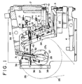
- Figure 1 shows a button setting machine incorporating an apparatus for adjusting the stroke of a light projector according to the present invention.
- the button setting machine includes a punch 1 for forcing an upper element A of a garment fastener such as a stud button into clinching engagement with a lower element (not shown) of the garment fastener.
- the punch 1 is reciprocable vertically with respect to a frame 2 of the button setting machine.
- a die 3 is supported by the frame 2 directly below the punch 1 for holding thereon the lower fastener element.
- the punch 1 and the die 3 cooperate with each other to clinch the upper and lower fastener elements with a garment fabric disposed therebetween.
- the die 3 is connected at its lower end to one end of a lever 4 which is connected at its opposite end to a shock absorber (not shown) for taking up or absorbing a shock force applied to the die 3 when the upper and lower fastener elements are clinched together.
- a shock absorber (not shown) for taking up or absorbing a shock force applied to the die 3 when the upper and lower fastener elements are clinched together.
- the button setting machine further includes an upper pusher 5 for receiving an upper fastener element A at a time from an upper chute 6 and for supplying the upper fastener element A to an upper pocket 7 disposed immediately below the punch 1 for holding the upper fastener element A.
- the upper pusher 5 is pivoted to an upper pusher lever 8 so that it is movable alternately back and forth along a horizontal path in response to the pivotal movement of the upper pusher lever 8.
- a tension coil spring 9 acts between the upper pusher lever 8 and the upper pusher 5 to urge the latter slightly upwardly for holding the horizontal posture of the upper pusher 5.
- a light projector 10 is associated with the button setting machine for indicating a position on the garment fabric where a garment fastener is to be attached.
- the light projector 10 is pivotably connected to one end of an actuating lever 11, the opposite end of the actuating lever 11 being connected to one end of a tension coil spring 12.
- the opposite end of the tension coil spring 12 is connected to the frame 2 so that the actuating lever 11 is normally urged by the tension coil spring 12 in a direction to retract the light projector 10 from the path of movement of the punch 1.
- the actuating lever 11 is pivoted on a horizontal shaft 13 secured to the frame 2.
- the actuating lever 11 is provided with an abutment block 14 which is held in contact with a roller 15 on the upper pusher lever 8 during a portion of the reciprocating stroke of the upper pusher 5.
- the abutment block 14 may be integral with the actuating lever 11. Alternatively, the abutment block 14 may be omitted in which instance the roller 15 directly engages a portion of the actuating lever 11.
- a stopper 16 is engageable with the actuating lever 11 to limit pivotal movement of the same for restricting the backward stroke of the light projector 10.
- the stopper 16 comprises a screw and hence is adjustable in position so that the reciprocating stroke of the light projector 10 can be adjusted by turning the stopper 16 in either direction.
- the light projector 10 includes a cylindrical rod 17 having one end grasped by a split holder 18. As shown in Figure 2, the split holder 18 is mounted astride the cylindrical rod 17 and secured to the same by a screw 19.
- the holder 18 has a flanged end portion 20 facing in a direction perpendicular to the axis of the cylindrical rod 17 and pivotably connected to the lower end of the actuating lever 11, with the actuating lever 11 held between the flanged end portion 20 and a retainer plate 20a.
- the flanged end portion 20 has a cylindrical projection 20b extending transverse to the axis of the cylindrical rod 17 and slidably received in a hole 11a in the lower end of the actuating lever 11.
- a bias means comprising a leaf spring 21 is connected at one end to the lower end of the actuating lever 11 and has the opposite end acting on the underside of the cylindrical rod 17 for urging the latter in a direction to lift the light projector 10.
- the leaf spring 21 may be replaced by a tension spring, not shown, acting between the actuating lever 11 and the cylindrical rod 17 to urge the light projector 10 upwardly.
- a lower pusher 22 is movably supported on the frame 2 for receiving a lower fastener element at a time from a lower chute 23 and for supplying the lower fastener element to the die 3.
- the lower pusher 22 is pivoted to a lower pusher lever 24 and horizontally reciprocable in response to the pivotal movement of the lower pusher lever 24.
- the forward end of the lower pusher 22 is disposed behind (left side in Figure 1) the lower end of the lower chute 23.
- the punch 1, the upper pusher 5 and the lower pusher 22 are all driven by a common drive unit including a fly wheel 26 continuously rotated by an electric motor (not shown) via a V-belt 25.
- a radial disk cam 27 is concentrically mounted on a central shaft of the fly wheel 26 via a single-revolution clutch (not shown).
- the single-revolution clutch is engaged to connect the continuously rotating fly wheel 26 and the cam 27 when a foot pedal (not shown) is depressed. When the cam 27 completes one revolution, the single-revolution clutch is disengaged to separate the cam 27 from the continuously rotating fly wheel 26.
- the cam 27 has an eccentric pin 28 projecting from an end face thereof and pivoted to a lower end of a crank lever 29.
- the crank lever 29 is directly connected at its upper end with a shaft 30 slidably received in a cylinder member 31.
- the shaft 30 has an actuator in the form of an annular flange 32 engageable with the lower end of the cylinder member 31.
- the actuating flange 32 is spaced a distance D from the lower end of the cylinder member 31 when the punch 1 is in its uppermost position.
- the upper end of the cylinder member 31 is pivoted to one end of a T-shaped lever 33, the opposite end of the T-shaped lever 33 being operatively connected to an upper end of the punch 1.
- the T-shaped lever 33 is pivotally movable about a shaft 34 to reciprocate the punch 1 vertically toward and away from the die 3.
- the shaft 30 immediately starts moving upwardly into the cylinder member 31.
- pivotal movement of the T-shaped lever 33 does not take place until the annular actuating flange 32 on the shaft 30 abuts against the lower end of the cylinder member 31.
- the shaft 30 and the cylinder member 31 jointly constitute a lost motion mechanism 35 which produces the lost motion or the delay between the movement of a driver (cam 27 in the illustrated embodiment) and the movement of a follower (the T-shaped lever 33 in the illustrated embodiment).
- a vertical cam lever 36 is pivotally connected at its lower end to a horizontal shaft 38 secured to the frame 2 and has a roller follower 23 rollingly engageable with a cam surface 27a of the cam 27.
- cam 27 rotates
- the cam lever 36 angularly oscillates about the shaft 38.
- the cam lever 36 is normally urged by a tension coil spring 39 toward the cam 27.
- the cam lever 36 is pivoted at its upper end portion to one end of a horizontal actuating rod 40, the opposite end of the actuating rod 40 being connected with the upper pusher lever 8.
- the T-shaped lever 33 has a vertical arm 41 extending downwardly from a substantially central portion thereof and pivotally connected at its distal end to one end of an expansion pipe joint 42.
- the opposite end of the expansion pipe joint 42 is pivoted to the lower pusher lever 24 adjacent to an upper end thereof.
- the expansion pipe joint 42 is composed of an outer pipe 43 connected to the arm 41 and an inner pipe 44 connected to the lower pusher lever 24 and slidably received in the outer pipe 43.
- the lower pusher lever 24 follows the pivotal movement of the T-shaped lever 33 in the counterclockwise direction, however, this angular movement of the lower pusher lever 24 is caused by the force of a tension coil spring 24a and not resulted from the pivotal movement of the T-shaped lever 33. Consequently, when a lower fastener element jams as it is fed by the lower pusher 22 toward the die 3, advancing movement of the lower pusher 22 is interrupted by the jamming lower fastener element while at the same time the T-shaped lever 33 continues its pivotal movement in the counterclockwise direction.
- the lower pusher lever 24 is forced by the T-shaped lever 33 to turn counterclockwise, thereby forcibly advancing the lower pusher 22 even when jamming of the lower fastener element takes place. Such forcible feeding of the jamming fastener element would damage the button setting machine.
- a tension coil spring 45 acts between the lower pusher lever 24 and the lower pusher 22 to urge the latter slightly upwardly so as not to sink the forward end of the lower pusher 22.
- the button setting machine of the foregoing construction operates as follows. For purposes of illustration, operation of the button setting machine begins from a condition shown in Figure 1. When a start switch (not shown) of the button setting machine is turned on, the motor-driven fly wheel 26 rotates continuously. In this instance, the single-revolution clutch is in the disengaged state so that the rotational movement of the fly wheel 26 is not transmitted to the cam 27.
- the light projector 10 projects a light beam passing along a common vertical axis of the punch 1 and the die 3. The light beam produces a light spot on a garment fabric when the latter is disposed between the light projector 10 and the die 3.
- the actuating lever 11 turns about the shaft 13 in the same direction under the force of the tension coil spring 12.
- This angular movement of the actuating lever 11 discontinues when an upper portion of the actuating lever 11 abuts against the stopper 16.
- the light projector 10 is disposed in its fully retracted position indicated by the phantom lines shown in Figure 1.
- the angular movement of the cam lever 36 continues to further retract the upper pusher 5 until the forward end of the upper pusher 5 is disposed behind the lower end of the upper chute 6.
- the backward stroke of the light projector 10 is considerably shorter than the backward stroke of the upper pusher 5.
- the reciprocating movement of the light projector 10 does not involve a wasteful extension and is unlikely to cause a breaking of lead wires of the light projector 10.
- the retracting movement of the upper pusher 5 is completed before the cam 27 advances through an angular distance which is equivalent to a linear advancing movement of the shaft 30 over the distance D (i.e., the lost motion) provided by the lost motion mechanism 35.
- the lost motion mechanism 35 With the action of the lost motion mechanism 35, the T-shaped lever 33 is kept immovable so that downward movement of the punch 1 never occurs before the upper pusher 5 is fully retracted.
- a continuing clockwise movement of the cam 27 causes the eccentric pin 28 to further advance the shaft 30 into the cylinder member 31 whereupon the annular actuating flange 32 on the shaft 30 is brought into abutment with the lower end of the cylinder member 31. Thereafter, the shaft 30 and the cylinder member 31 move upwardly in unison with each other, thus causing the T-shaped lever 33 to turn about the shaft 34 in the clockwise direction to thereby lower the punch 1 toward the die 3.
- the fully retracted position of the light projector 10, that is, the stroke of the light projector 10 can be adjusted by turning the threaded stopper 16 in either direction.
- the stroke of the light projector can be adjusted separately from the stroke of the upper pusher without the necessity of providing a separate drive unit used exclusively for reciprocating the light projector. Since the stroke of the light projector is considerably shorter than the stroke of the upper pusher, the reciprocating movement of the light projector can be achieved without loss. Furthermore, the light projector having such short stroke is unlikely to cause a breaking of lead wires and hence is easy to maintain.
Landscapes
- Engineering & Computer Science (AREA)
- Textile Engineering (AREA)
- Portable Nailing Machines And Staplers (AREA)
- Projection Apparatus (AREA)
- Sewing Machines And Sewing (AREA)
- Non-Portable Lighting Devices Or Systems Thereof (AREA)
Claims (5)
- Appareil pour régler la course d'un projecteur de lumière (10) déplaçable en va-et-vient horizontal dans une machine à fixer les boutons comprenant un poinçon (1) déplaçable en va-et-vient vertical et un poussoir supérieur (5) déplaçable en va-et-vient horizontal pour amener un élément de fixation (A) dans un trajet de déplacement dudit poinçon (1), la machine à fixer les boutons comprenant un élément d'entraînement (26) entraîné par un moteur, le projecteur de lumière (10) étant normalement placé directement en dessous du poinçon (1) et étant relié de façon opérationnelle audit poussoir supérieur (5), ledit appareil comprenant des premiers moyens (27 ; 36 ; 40 ; 8) pour transmettre une puissance d'entraînement de l'élément d'entraînement (26) au poussoir supérieur (5) et des seconds moyens (28-33 ; 24) pour transmettre une puissance d'entraînement de l'élément d'entraînement (26) au poinçon (1) ainsi que des moyens mécaniques (27-31) pour produire un temps de retard entre le déplacement de retrait du projecteur de lumière (10) à la descente du poinçon (1) suffisamment pour que le projecteur de lumière (10) se soit retiré du trajet vertical de déplacement du poinçon (1) avant que le poinçon (1) ne commence à descendre, ledit appareil comprenant en outre :(a) un levier d'actionnement (11) mobile par pivotement autour d'un arbre (13) en réponse au mouvement de va-et-vient du poussoir supérieur (5),(b) un support (18) relié de façon pivotante à une extrémité dudit levier d'actionnement (11) et maintenant une tige (17), ledit projecteur (10) étant relié à l'extrémité libre de ladite tige (17),(c) un moyen de sollicitation (21) pour pousser ladite tige (17) vers le haut,(d) un moyen formant ressort (12) pour pousser ledit levier d'actionnement (11) dans une direction de retrait dudit projecteur de lumière (10) hors du trajet de déplacement du poinçon (1) et l'amener en butée avec un organe (8) relié audit poussoir supérieur (5), et(e) une butée réglable (16) engageable avec ledit levier d'actionnement (11) pour limiter le mouvement pivotant de celui-ci dans ladite direction, à l'encontre de la force dudit moyen formant ressort (12).
- Appareil selon la revendication 1, dans lequel ledit support (18) est bifurqué et est monté à cheval sur ladite tige (17).
- Appareil selon la revendication 1, dans lequel ladite première extrémité dudit levier d'actionnement (11) comporte un trou (11a) et ledit support (18) est placé sur un côté dudit levier d'actionnement et comprend une saillie latérale (20b) qui s'étend transversalement à un axe longitudinal de ladite tige (17) et est reçu de façon coulissante dans ledit trou (11a) dudit levier d'actionnement (11), comportant en outre une plaque de retenue (20a) placée sur le côté opposé dudit levier d'actionnement (11) et fixée à ladite saillie latérale (20b).
- Appareil selon la revendication 1, dans lequel ledit moyen de sollicitation (21) comprend un ressort à lame ayant une extrémité reliée audit levier d'actionnement (11) et l'extrémité opposée qui agit sur le côté de dessous de ladite tige (17).
- Appareil selon la revendication 1, dans lequel ladite butée réglable (16) comprend une vis.
Applications Claiming Priority (2)
| Application Number | Priority Date | Filing Date | Title |
|---|---|---|---|
| JP12489/89U | 1989-02-03 | ||
| JP1989012489U JPH0714336Y2 (ja) | 1989-02-03 | 1989-02-03 | 投光器のストローク調整装置 |
Publications (3)
| Publication Number | Publication Date |
|---|---|
| EP0381227A2 EP0381227A2 (fr) | 1990-08-08 |
| EP0381227A3 EP0381227A3 (en) | 1990-11-22 |
| EP0381227B1 true EP0381227B1 (fr) | 1994-05-04 |
Family
ID=11806811
Family Applications (1)
| Application Number | Title | Priority Date | Filing Date |
|---|---|---|---|
| EP90102085A Expired - Lifetime EP0381227B1 (fr) | 1989-02-03 | 1990-02-02 | Dispositif d'ajustement du coup pour le projecteur de lumière d'une machine à fixer les boutons |
Country Status (6)
| Country | Link |
|---|---|
| US (1) | US5060839A (fr) |
| EP (1) | EP0381227B1 (fr) |
| JP (1) | JPH0714336Y2 (fr) |
| CA (1) | CA2008469C (fr) |
| DE (1) | DE69008552T2 (fr) |
| ES (1) | ES2052079T3 (fr) |
Families Citing this family (5)
| Publication number | Priority date | Publication date | Assignee | Title |
|---|---|---|---|---|
| DE4408691C1 (de) * | 1994-03-15 | 1995-08-17 | Stocko Metallwarenfab Henkels | Maschine zum Ansetzen von Nieten, Druckknöpfen und dergleichen |
| US5781989A (en) * | 1996-11-27 | 1998-07-21 | Eastlex Machine Corporation | Fastener attaching apparatus |
| JP3971124B2 (ja) | 2001-04-26 | 2007-09-05 | Ykk株式会社 | ボタンの取付力設定方法 |
| WO2005102612A2 (fr) * | 2004-04-20 | 2005-11-03 | Acco Brands Usa Llc | Agrafeuse |
| US9421599B2 (en) * | 2010-11-16 | 2016-08-23 | Btm Company Llc | Clinch clamp |
Family Cites Families (13)
| Publication number | Priority date | Publication date | Assignee | Title |
|---|---|---|---|---|
| US3964661A (en) * | 1974-10-23 | 1976-06-22 | Textron, Inc. | Apparatus for attaching pronged and mating elements to articles |
| JPS6013929U (ja) * | 1983-07-08 | 1985-01-30 | 日本ノ−シヨン工業株式会社 | 釦加工装置 |
| JPS60126731A (ja) * | 1983-12-14 | 1985-07-06 | Hitachi Ltd | プログラム制御方法 |
| CA1257076A (fr) * | 1983-12-29 | 1989-07-11 | Yukio Taga | Dispositif d'assemblage d'une paire d'elements de fixation |
| JPS60113322U (ja) * | 1983-12-29 | 1985-07-31 | 日本ノ−シヨン工業株式会社 | 釦取付機における取付位置指示装置 |
| JPS6147029U (ja) * | 1984-08-30 | 1986-03-29 | 日本ノ−シヨン工業株式会社 | 釦加工装置 |
| US4573834A (en) * | 1984-12-31 | 1986-03-04 | Kabushiki Kaisha Kawakami Seisakusho | Piercer |
| GB2191139B (en) * | 1986-05-28 | 1990-03-28 | Scovill Japan | Marking light |
| JPH0765241B2 (ja) * | 1986-05-28 | 1995-07-12 | スコ−ビル・ジヤパン株式会社 | マ−キングライトの安全装置 |
| JPS6321534A (ja) * | 1986-07-14 | 1988-01-29 | Mitsubishi Cable Ind Ltd | 光フアイバの評価方法 |
| JPS6342908A (ja) * | 1986-08-06 | 1988-02-24 | ワイケイケイ株式会社 | 部品自動取付機 |
| JPH0311208Y2 (fr) * | 1986-08-26 | 1991-03-19 | ||
| JPH0435287Y2 (fr) * | 1986-08-26 | 1992-08-21 |
-
1989
- 1989-02-03 JP JP1989012489U patent/JPH0714336Y2/ja not_active Expired - Lifetime
-
1990
- 1990-01-22 US US07/468,358 patent/US5060839A/en not_active Expired - Fee Related
- 1990-01-24 CA CA002008469A patent/CA2008469C/fr not_active Expired - Fee Related
- 1990-02-02 DE DE69008552T patent/DE69008552T2/de not_active Expired - Fee Related
- 1990-02-02 ES ES90102085T patent/ES2052079T3/es not_active Expired - Lifetime
- 1990-02-02 EP EP90102085A patent/EP0381227B1/fr not_active Expired - Lifetime
Also Published As
| Publication number | Publication date |
|---|---|
| ES2052079T3 (es) | 1994-07-01 |
| US5060839A (en) | 1991-10-29 |
| CA2008469A1 (fr) | 1990-08-03 |
| EP0381227A2 (fr) | 1990-08-08 |
| CA2008469C (fr) | 1994-05-10 |
| DE69008552D1 (de) | 1994-06-09 |
| DE69008552T2 (de) | 1994-12-08 |
| JPH0714336Y2 (ja) | 1995-04-05 |
| EP0381227A3 (en) | 1990-11-22 |
| JPH02106432U (fr) | 1990-08-23 |
Similar Documents
| Publication | Publication Date | Title |
|---|---|---|
| US4799611A (en) | Apparatus for assembling pairs of garment fastener elements | |
| JPH0526275U (ja) | 釘打機における打込み深さ調整装置 | |
| EP0381226B1 (fr) | Dispositif pour protéger un projecteur de lumière d'une collision avec le poinçon d'une machine à fixer les boutons | |
| EP0381227B1 (fr) | Dispositif d'ajustement du coup pour le projecteur de lumière d'une machine à fixer les boutons | |
| US4122988A (en) | Pierce rivet machine | |
| GB2150249A (en) | Apparatus for assembling a pair of fastener elements | |
| EP0261361B1 (fr) | Machine de fixation d'éléments de fermeture de vêtement pourvue d'un indicateur de position commandée par un plongeur | |
| EP0173248B1 (fr) | Appareil pour assembler une paire d'éléments de fermeture | |
| EP0920963A1 (fr) | Dispositif d'agrafage | |
| JPS5921691B2 (ja) | 衝撃プレス | |
| US2650360A (en) | Automatic stapling machine | |
| US1983384A (en) | Wire-stitching machine | |
| EP0549969B1 (fr) | Machine de sertissage pour éléments de bouton | |
| US3528331A (en) | Punch machine | |
| US3753523A (en) | Stapling machine | |
| US4279335A (en) | Safety device having machine drive cam control | |
| US4020721A (en) | Apparatus and method for cutting continuous stock | |
| US4342215A (en) | Nail machine wire feed mechanism | |
| US3810381A (en) | Detachable slidable form block for reciprocating die press | |
| EP0641629A1 (fr) | Dispositif d'alimentation des éléments de fixation | |
| SU1719145A1 (ru) | Устройство дл изготовлени и расклепки штырей в платах | |
| US4056870A (en) | Hand held powered metal clinching tool | |
| JPH0724884B2 (ja) | 材料給送装置 | |
| SU1411082A1 (ru) | Устройство дл подачи полосового и ленточного материала в рабочую зону пресса | |
| JP2558319Y2 (ja) | 打撃工具 |
Legal Events
| Date | Code | Title | Description |
|---|---|---|---|
| PUAI | Public reference made under article 153(3) epc to a published international application that has entered the european phase |
Free format text: ORIGINAL CODE: 0009012 |
|
| AK | Designated contracting states |
Kind code of ref document: A2 Designated state(s): BE DE ES FR GB IT |
|
| PUAL | Search report despatched |
Free format text: ORIGINAL CODE: 0009013 |
|
| AK | Designated contracting states |
Kind code of ref document: A3 Designated state(s): BE DE ES FR GB IT |
|
| 17P | Request for examination filed |
Effective date: 19901218 |
|
| 17Q | First examination report despatched |
Effective date: 19930705 |
|
| GRAA | (expected) grant |
Free format text: ORIGINAL CODE: 0009210 |
|
| AK | Designated contracting states |
Kind code of ref document: B1 Designated state(s): BE DE ES FR GB IT |
|
| ET | Fr: translation filed | ||
| ITF | It: translation for a ep patent filed |
Owner name: JACOBACCI CASETTA & PERANI S.P.A. |
|
| REF | Corresponds to: |
Ref document number: 69008552 Country of ref document: DE Date of ref document: 19940609 |
|
| ITPR | It: changes in ownership of a european patent |
Owner name: CAMBIO RAGIONE SOCIALE;YKK CORPORATION |
|
| RAP2 | Party data changed (patent owner data changed or rights of a patent transferred) |
Owner name: YKK CORPORATION |
|
| REG | Reference to a national code |
Ref country code: FR Ref legal event code: CD |
|
| REG | Reference to a national code |
Ref country code: ES Ref legal event code: PC2A Owner name: YKK CORPORATION |
|
| PLBE | No opposition filed within time limit |
Free format text: ORIGINAL CODE: 0009261 |
|
| STAA | Information on the status of an ep patent application or granted ep patent |
Free format text: STATUS: NO OPPOSITION FILED WITHIN TIME LIMIT |
|
| 26N | No opposition filed | ||
| PGFP | Annual fee paid to national office [announced via postgrant information from national office to epo] |
Ref country code: BE Payment date: 19951129 Year of fee payment: 7 |
|
| PGFP | Annual fee paid to national office [announced via postgrant information from national office to epo] |
Ref country code: FR Payment date: 19951220 Year of fee payment: 7 |
|
| PGFP | Annual fee paid to national office [announced via postgrant information from national office to epo] |
Ref country code: GB Payment date: 19960124 Year of fee payment: 7 |
|
| PGFP | Annual fee paid to national office [announced via postgrant information from national office to epo] |
Ref country code: ES Payment date: 19960201 Year of fee payment: 7 |
|
| PGFP | Annual fee paid to national office [announced via postgrant information from national office to epo] |
Ref country code: DE Payment date: 19960329 Year of fee payment: 7 |
|
| PG25 | Lapsed in a contracting state [announced via postgrant information from national office to epo] |
Ref country code: GB Effective date: 19970202 |
|
| PG25 | Lapsed in a contracting state [announced via postgrant information from national office to epo] |
Ref country code: ES Free format text: LAPSE BECAUSE OF NON-PAYMENT OF DUE FEES Effective date: 19970203 |
|
| PG25 | Lapsed in a contracting state [announced via postgrant information from national office to epo] |
Ref country code: BE Effective date: 19970228 |
|
| BERE | Be: lapsed |
Owner name: YKK CORP. Effective date: 19970228 |
|
| GBPC | Gb: european patent ceased through non-payment of renewal fee |
Effective date: 19970202 |
|
| PG25 | Lapsed in a contracting state [announced via postgrant information from national office to epo] |
Ref country code: FR Effective date: 19971030 |
|
| PG25 | Lapsed in a contracting state [announced via postgrant information from national office to epo] |
Ref country code: DE Effective date: 19971101 |
|
| REG | Reference to a national code |
Ref country code: FR Ref legal event code: ST |
|
| REG | Reference to a national code |
Ref country code: ES Ref legal event code: FD2A Effective date: 19990301 |
|
| PG25 | Lapsed in a contracting state [announced via postgrant information from national office to epo] |
Ref country code: IT Free format text: LAPSE BECAUSE OF NON-PAYMENT OF DUE FEES;WARNING: LAPSES OF ITALIAN PATENTS WITH EFFECTIVE DATE BEFORE 2007 MAY HAVE OCCURRED AT ANY TIME BEFORE 2007. THE CORRECT EFFECTIVE DATE MAY BE DIFFERENT FROM THE ONE RECORDED. Effective date: 20050202 |