EP0380739B1 - Verfahren sowie Spannvorrichtung zum zeitweiligen Festlegen von Werkstücken - Google Patents
Verfahren sowie Spannvorrichtung zum zeitweiligen Festlegen von Werkstücken Download PDFInfo
- Publication number
- EP0380739B1 EP0380739B1 EP89111835A EP89111835A EP0380739B1 EP 0380739 B1 EP0380739 B1 EP 0380739B1 EP 89111835 A EP89111835 A EP 89111835A EP 89111835 A EP89111835 A EP 89111835A EP 0380739 B1 EP0380739 B1 EP 0380739B1
- Authority
- EP
- European Patent Office
- Prior art keywords
- piston
- piston rod
- clamping
- hydraulic oil
- clamping device
- Prior art date
- Legal status (The legal status is an assumption and is not a legal conclusion. Google has not performed a legal analysis and makes no representation as to the accuracy of the status listed.)
- Expired - Lifetime
Links
Images


Classifications
-
- B—PERFORMING OPERATIONS; TRANSPORTING
- B25—HAND TOOLS; PORTABLE POWER-DRIVEN TOOLS; MANIPULATORS
- B25B—TOOLS OR BENCH DEVICES NOT OTHERWISE PROVIDED FOR, FOR FASTENING, CONNECTING, DISENGAGING, OR HOLDING
- B25B5/00—Clamps
- B25B5/06—Arrangements for positively actuating jaws
- B25B5/061—Arrangements for positively actuating jaws with fluid drive
-
- B—PERFORMING OPERATIONS; TRANSPORTING
- B23—MACHINE TOOLS; METAL-WORKING NOT OTHERWISE PROVIDED FOR
- B23D—PLANING; SLOTTING; SHEARING; BROACHING; SAWING; FILING; SCRAPING; LIKE OPERATIONS FOR WORKING METAL BY REMOVING MATERIAL, NOT OTHERWISE PROVIDED FOR
- B23D47/00—Sawing machines or sawing devices working with circular saw blades, characterised only by constructional features of particular parts
- B23D47/04—Sawing machines or sawing devices working with circular saw blades, characterised only by constructional features of particular parts of devices for feeding, positioning, clamping, or rotating work
Definitions
- the invention relates to a method for temporarily fixing workpieces, in particular hollow profiles, in machine tools with the aid of a clamping device, the clamping element of which is moved by the piston and the piston rod of a hydraulic working cylinder in the feed and return directions, with hydraulic oil on the the feed of the clamping element Piston rod side is displaced and flows off.
- the invention also relates to a tensioning device, in particular for carrying out the method with a tensioning element which can be moved by the piston and the piston rod of a hydraulic working cylinder, wherein hydraulic oil is applied when the tensioning element is advanced and the pressure medium flows in on the side facing away from the piston rod and during its axial adjustment the side having the piston rod is displaced.
- Clamping devices of the type described in the introduction are, for example used in sawing machines in which the workpiece to be processed must be held securely and firmly, for example during the cutting or sawing process.
- workpieces made of full material and a stable profile shape can also be clamped with comparatively high clamping forces.
- Workpieces made of elastic and resilient material or with unstable profile shapes can only be loaded with a limited clamping pressure if the workpiece does not lose its external shape completely and should not be flattened. If, for example, the machine tool also permits the processing of different types of materials or profile shapes, the clamping pressure exerted on the workpiece in question must be adjusted in accordance with its elasticity and instability.
- the pressure of the hydraulic oil in the piston chamber has been regulated or limited in the piston rod chamber of the clamping cylinder by means such as those in the exercise book for the trainee ", Federal Office for Vocational Training, ISDN No. 3 / 410-38287-9, Beuth-Verlag, Berlin , Page 105 and 106. And are the basis for the preamble of the claims.
- the pressure control in the piston chamber however, the cylinder is often re-pressed when the workpiece is sawn through.
- the piston rod also moves more slowly in the area of the minimum clamping force than with full one
- a pressure reducing valve used in the pressure control in the piston chamber represents a sensitive control element which is particularly exposed to the risk of contamination and damage.
- the pressure limitation in the rod space is often associated with similar disadvantages.
- the cylinder is usually repressed when the workpiece is sawn through.
- the piston rod moves extremely slowly.
- the minimum clamping force for the pressure limitation in the bar space is relatively high due to its operating principle. It also has one Pressure limitation usually a poor repeatability.
- the feed movement of the tensioning element is therefore stopped if, for example, the counter pressure developed against the resistance and the resistance of the material to deformation on the one hand and the maximum tension pressure on the other hand are in equilibrium.
- the clamping force used during clamping is practically automatically adjusted to the respective profile and solid material. In this way, for example, comparatively unstable hollow profiles can be clamped quickly, safely and securely with sufficient clamping pressure.
- a device for different hydraulic clamping of workpieces, in particular for lathes is known, with which flexible workpieces that are out of round due to a large clamping force can be clamped.
- a clamping piston acted upon on both sides with hydraulic oil is provided in a clamping cylinder, with the aid of which the chuck can be loosened after a first firmer clamping so that the previously larger deformation of the workpiece is sufficiently reduced, but the workpiece remains clamped for post-processing.
- the clamping side of the clamping cylinder is equipped with an additional space, e.g. an auxiliary cylinder, connectable and the release side of the clamping cylinder can be acted upon with high pressure oil.
- a hydraulic system with an arrangement of valves and slides is required, by means of which the clamping side can be separated from the high-pressure supply line and connected to the auxiliary cylinder, then the release side of the clamping cylinder can be supplied with high-pressure oil and finally the clamping side of the clamping cylinder can be supplied with low-pressure oil and the release side of the Clamping cylinder can be connected to an outlet.
- the clamping pressure used during clamping can also be arbitrarily adjusted in such a way that an unintentional and excessive deformation of the workpiece is largely prevented, namely by the partial quantity of hydraulic oil still displaced after the clamping element hits the workpiece, depending on the elasticity or compliance of the clamped Workpieces are changed.
- the solution according to the invention consists in particular in that the piston is designed as a sliding piston which can be displaced relative to the piston rod by a limited path, that at least one return opening is provided on the piston rod for the hydraulic oil to be displaced during the feed, and the sliding piston in a relative adjustment in the axial direction closes this return opening, and that the cylinder space located on the side of the piston rod has or is connected to an adjoining space.
- the clamping element Due to the operating pressure in the working cylinder that is effective during feed, the clamping element is first moved into its clamping position. The hydraulic oil on the piston rod side of the piston flows out of this area through the return opening. If the piston rod hits the workpiece, the piston rod is initially braked in its feed movement. The operating pressure in the working cylinder, which is still effective on the sliding piston, moves the sliding piston via the return opening provided on the piston rod, so that the main outflow of the hydraulic oil displaced during the feed is blocked. The hydraulic oil still remaining on the side with the piston rod can now be removed
- the volume of the adjoining space connected to the cylinder space can be changed in order to be able to adapt the clamping pressure to the deformability and lability of a workpiece.
- the adjoining room contains a piston which is acted upon or acted upon by a restoring force and the restoring force is preferably a spring, in particular a compression spring, or a piston.
- the displacement path of the piston located in the adjoining room is limited by a stop which can be adjusted and fixed in the displacement direction of the piston.
- a stop which can be adjusted and fixed in the displacement direction of the piston.
- the adjustable stop is expediently designed as a screw or spindle oriented in the direction of the piston travel.
- a simple and advantageous further development according to the invention provides that the spring serving to reset the piston located in the adjoining room can be changed in its position in the direction of displacement of the piston and preferably on one in the direction of displacement of the piston adjustable and fixable counter plate supports.
- an automatic adjustment of the clamping force exerted on the workpiece can be achieved, for example, to the respective profile and the material type or thickness.
- the adjustability of the spring results in different setting ranges, which only have to be changed, for example, for a different type of material and / or for a fundamentally different profile shape.
- the wall thickness of the profile only plays a subordinate role, ie a setting range that has been set covers thin and thick-walled profiles up to the solid material.
- the counter plate is expediently or the like via a spindle, a screw. Adjustable element.
- a partial flow of the hydraulic oil displaced by the return opening when the tensioning element is advanced serves to reset the piston located in the adjoining room.
- a spring is not necessary as a restoring force for resetting the piston located in the adjoining room.
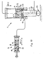
- FIG. 1 shows a partial longitudinal section of the hydraulic working cylinder 1 of a clamping device for temporarily fixing and fixing workpieces in the region of the displacement path of its piston 2.
- the clamping device which is not shown in FIG. 1, can advantageously be used, for example, in a sawing machine, in order to hold workpieces of different elasticity and in particular also hollow profiles securely and firmly in their position during the sawing and cutting process, without the workpiece, which may also be flexible in its shape, being flattened excessively or even completely during clamping.
- the - not shown here - clamping element of this clamping device with which the workpiece is clamped, is moved in the feed and reset direction by a piston 2 guided in the working cylinder 1 and a piston rod 3 connected to the piston 2.
- the piston 2 which is acted upon by the operating pressure and pressed in the feed direction Pf 1, displaces hydraulic oil on the side of the piston 2 which has the piston rod 3 through return openings 4 which end in a common, outer radial groove 25 of the piston rod 3.
- the piston 2 is designed according to the invention as a sliding piston that is adjustable by a limited path relative to the piston rod 3.
- the displacement path of the sliding piston 2 relative to the piston rod 3 is limited on the one hand by a stop surface 5 provided on the piston-side end region of the piston rod 3 or a stop collar and on the other hand by a retaining ring 6 which is fastened practically immovably on the piston rod 3 in the axial direction.
- a rod extension 7 of smaller diameter provided on the piston-side end region of the piston rod 3 serves as an inner and passage openings for the hydraulic oil ring flange 8 of the piston 2 as a guide between the heel or stop surface and the locking ring 6.
- the locking ring 6 engages in a locking groove on Rod extension 7 a.
- the essentially piston-shaped sliding piston 2 engages with its peripheral wall 9 around the end region of the piston rod 3 on the piston side.
- this piston rod 3 is designed as a hollow rod that runs through to the piston 2.
- a plurality of radial return openings 4 for the hydraulic oil are provided, which connect the inner cavity 10 of the piston rod 3 with the region of the working cylinder on the piston rod side.
- the hydraulic oil displaced by the sliding piston 2 moving in the feed direction can flow out through the inner cavity 10 via an outflow opening 11 provided outside the cylinder on the piston rod 3 from the region on the piston rod side.
- the sliding piston 2 closes these return openings 4 and thus blocks the main outflow of the hydraulic oil.
- the hydraulic oil still remaining on the side of the piston rod 3 in the working cylinder 1 can only flow and be displaced via the secondary outflow 13 into an adjoining space designed as a displacement cylinder 14 with displacement piston 15, for example if a workpiece that yields under the operating or clamping pressure even after the piston rod 3 strikes, allows a displacement movement of the piston rod 3 in the feed direction Pf 1.
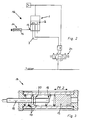
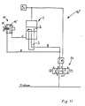
- FIG. 2 The structure of a tensioning device 16 according to the invention is shown schematically in the block diagram from FIG.
- the tensioning element connected to the piston rod 3 and not shown here can be moved in the feed or reset direction via a 3-way valve 24 will. From FIG. 2 it can also be clearly seen that the side of the piston 2 which has the piston rod 3 or the region in question is connected to the side room via a secondary outlet 13.
- This side room is shown in more detail in a longitudinal section in FIG. 3. From Fig. 3 it is clear that the adjoining room is designed as a displacement cylinder 14, in which a displacement piston 15 which can be acted upon with hydraulic oil toward the secondary outlet 13 (cf. FIG. 2) is movably guided. Due to the displacer piston 15, which is movably guided in the displacement cylinder 14, the volume of the secondary space connected to the cylinder space can be changed. A compression spring 17 acts in the displacement cylinder 14 as a restoring force for the displacement piston 15 and acts on the displacement piston 15 on the side facing away from the secondary outlet 13 (see FIG. 2).
- the displacement path of the displacement piston 15 located in the secondary space designed as a displacement cylinder 14 can be limited by a stop 18 which is adjustable and fixable in the direction of displacement Pf 2 of the displacement piston 15.
- This adjustable stop 18 is designed as a spindle 19 oriented in the direction of the piston travel.
- the stop 18 or the spindle 18 is also arranged on the side of the displacement piston 15 facing away from the secondary outlet 13 (see FIG. 2).
- the volume available to the hydraulic oil displaced into the adjoining room can be limited by the spindle 19.
- a nut 20 which is countered by a lock nut prevents the spindle 19 serving as a stop 18 from being inadvertently completely unscrewed.
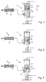
- FIGS. 4 to 10 The operation of the tensioning device according to the invention is to be illustrated in FIGS. 4 to 10.
- the clamping device 16 is schematically illustrated when clamping a workpiece 21 which is made of solid material and is accordingly also largely unyielding even under pressure.
- Fig. 4 shows the clamping device 16 at the beginning of the clamping process of the workpiece 21 in the starting position of its working cylinder 1 and the adjoining room.
- FIG. 5 shows the working cylinder 1 and the associated adjoining space of the clamping device 16 when it hits or places its piston rod 3 on the workpiece 21, which is designed here for illustration purposes without another clamping element. If the pressure piece - or here the piston rod 3 - touches the workpiece 21, the piston rod 3 cannot extend any further.
- the operating pressure on the side of the piston facing away from the piston rod 3 of the hydraulic oil flowing into the area during the feed now presses the sliding piston 2 against the stop surface 5 (see FIG. 6) into its lower relative position to the piston rod 3, in which it moves against the Piston rod 3 closes return openings 4 and hydraulically seals the cross section with its chamfer 12 against the O-ring.
- the clamping device 16 is also shown in FIGS. 7 to 16 when clamping a hollow profile tube and with a corresponding pressure in its shape, also flexible workpiece 22.
- the part of the hydraulic oil displaced thereby pushes, for example, a thin-walled workpiece 22, which initially does not provide any significant resistance to the operating pressure, pushes the displacer piston 15 in the displacer cylinder 14 against the spring force of the compression spring 17 to the adjustable stop 18.
- the piston rod moves 3 of the working cylinder 1 the path in the appropriate ratio of the areas of the two pistons 2.15 and deforms the thin-walled profile.
- both of the processes described in FIGS. 4 to 6 and 7 to 10 are possible, depending on the deformability of the workpiece and on the setting of the stop 18 in the displacement cylinder 14.
- the compression spring 17 in the displacement cylinder 14 influences the amount the workpiece deformation.
- a small clamping force on the workpiece and a large spring force in the displacement cylinder result in a large spring travel and a large clamping travel, such as is suitable for thin-walled profiles.
- a medium clamping force on the workpiece and medium spring force in the displacement cylinder there is, for example, a medium spring travel and a medium clamping travel, as is suitable for thick-walled profiles.
- maximum clamping force on the workpiece and minimum spring force the spring travel and the clamping travel are practically zero; this division of the maximum clamping force is suitable, for example, for clamping solid material.
- the inside of the piston facing the piston rod 3 is subjected to the operating pressure introduced into the working cylinder 1 through the hollow piston rod 3.
- the sliding piston 2 moves upward in FIG. 10, for example, and releases the discharge cross section of the return openings 4 again.
- the hydraulic oil can thus flow into the area of the working cylinder 1 which has the piston rod 3.
- the piston rod 3 moves back into the working cylinder 1.
- the compression spring 17 in the displacement cylinder 14 presses the displacement piston 15 back into its starting position.
- the clear inner diameter of the working cylinder 1 and the secondary space 14 'designed as a displacement cylinder are approximately the same size . Since the geometrical dimensions of the dimensions of the two cylinders - working cylinder 1 and displacement cylinder 14 '- are chosen to be the same, the part of the hydraulic fluid displaced into the adjoining room can also be accommodated in a comparatively short distance in the displacement cylinder 14'. In this way, the adjustment path for the limit stop of the displacer 15 'is reduced to a distance of, for example, approximately 1.5 mm, or the like with one turn of a screw. can be reached. This can be used for continuously variable settings on the screw, the spindle or the like. Adjusting element of the adjoining room a scale can be attached.
Landscapes
- Engineering & Computer Science (AREA)
- Mechanical Engineering (AREA)
- Jigs For Machine Tools (AREA)
- Machine Tool Sensing Apparatuses (AREA)
- Actuator (AREA)
- Automobile Manufacture Line, Endless Track Vehicle, Trailer (AREA)
Priority Applications (1)
| Application Number | Priority Date | Filing Date | Title |
|---|---|---|---|
| AT89111835T ATE80079T1 (de) | 1989-02-02 | 1989-06-29 | Verfahren sowie spannvorrichtung zum zeitweiligen festlegen von werkstuecken. |
Applications Claiming Priority (2)
| Application Number | Priority Date | Filing Date | Title |
|---|---|---|---|
| DE3903095 | 1989-02-02 | ||
| DE3903095A DE3903095C1 (enExample) | 1989-02-02 | 1989-02-02 |
Publications (3)
| Publication Number | Publication Date |
|---|---|
| EP0380739A2 EP0380739A2 (de) | 1990-08-08 |
| EP0380739A3 EP0380739A3 (en) | 1990-10-17 |
| EP0380739B1 true EP0380739B1 (de) | 1992-09-02 |
Family
ID=6373292
Family Applications (1)
| Application Number | Title | Priority Date | Filing Date |
|---|---|---|---|
| EP89111835A Expired - Lifetime EP0380739B1 (de) | 1989-02-02 | 1989-06-29 | Verfahren sowie Spannvorrichtung zum zeitweiligen Festlegen von Werkstücken |
Country Status (3)
| Country | Link |
|---|---|
| EP (1) | EP0380739B1 (enExample) |
| AT (1) | ATE80079T1 (enExample) |
| DE (2) | DE3903095C1 (enExample) |
Families Citing this family (3)
| Publication number | Priority date | Publication date | Assignee | Title |
|---|---|---|---|---|
| DE19537082A1 (de) * | 1995-10-05 | 1997-06-19 | Schubert Maschinen Und Anlagen | Abschnitt- und Stangenhalter für Stabstahlscheren |
| CN113339353A (zh) * | 2021-06-19 | 2021-09-03 | 华建电气有限公司 | 一种行程可调气缸 |
| CN115319659B (zh) * | 2022-09-02 | 2023-06-02 | 广东金志利科技股份有限公司 | 一种风力发电机组轴承座加工的定位装置 |
Family Cites Families (3)
| Publication number | Priority date | Publication date | Assignee | Title |
|---|---|---|---|---|
| FR2348787A1 (fr) * | 1976-04-23 | 1977-11-18 | Letestu Claude | Dispositif pour serrage de pieces entre deux organes mobiles l'un par rapport a l'autre |
| DE2654858C2 (de) * | 1976-12-03 | 1978-11-16 | Gustav Wagner Maschinenfabrik, 7410 Reutlingen | Mit hydraulischem Kolbengetriebe arbeitende Spannvorrichtung für Werkstücke |
| DE3031513A1 (de) * | 1980-08-21 | 1982-03-25 | Maschinenfabrik Hilma Gmbh, 5912 Hilchenbach | Doppelwirkender druckmittelzylinder |
-
1989
- 1989-02-02 DE DE3903095A patent/DE3903095C1/de not_active Expired
- 1989-06-29 DE DE8989111835T patent/DE58902206D1/de not_active Expired - Fee Related
- 1989-06-29 EP EP89111835A patent/EP0380739B1/de not_active Expired - Lifetime
- 1989-06-29 AT AT89111835T patent/ATE80079T1/de active
Also Published As
| Publication number | Publication date |
|---|---|
| EP0380739A2 (de) | 1990-08-08 |
| DE3903095C1 (enExample) | 1989-12-21 |
| EP0380739A3 (en) | 1990-10-17 |
| ATE80079T1 (de) | 1992-09-15 |
| DE58902206D1 (de) | 1992-10-08 |
Similar Documents
| Publication | Publication Date | Title |
|---|---|---|
| DE10206630B4 (de) | Verfahren und Vorrichtung zum Hochgeschwindigkeitspressen von Werkstücken | |
| DE2257384C3 (de) | Spannfutter für Drehmaschinen u.dgl. Werkzeugmaschinen | |
| DE2718776C2 (de) | Mit einem ersten Druckmittel betätigte Vorrichtung zur Erhöhung des Druckes eines zweiten Druckmittels in zwei Stufen | |
| DE2533502C3 (de) | Pneumatische Stangenvorschubeinrichtung für stangenverarbeitende Drehmaschinen | |
| DE2532408C3 (de) | Druckluftantrieb für Werkzeuge | |
| DE3637823C2 (de) | Hilfskraftbetätigtes Spannfutter | |
| EP0460457A2 (de) | Maschinenschraubstock | |
| DE19817882A1 (de) | Radialpresse | |
| DE2832981C2 (de) | Vorschubzylinder | |
| EP0380739B1 (de) | Verfahren sowie Spannvorrichtung zum zeitweiligen Festlegen von Werkstücken | |
| DE3329942C1 (de) | Spannvorrichtung für insbes. spanabhebend zu bearbeitende Werkstücke | |
| EP0785049B1 (de) | Auflagetisch mit einer Spannvorrichtung | |
| DE1552711C3 (de) | Durch Druckmittel betätigtes Spannelement | |
| DE2245796A1 (de) | Doppeltwirkender druckmittelzylinder | |
| DE2062890A1 (de) | Druckmittelbetriebener Arbeitszylinder | |
| DE3502362C2 (enExample) | ||
| EP0617202B1 (de) | Vorrichtung zur Endlagendämpfung eines bewegten Systems | |
| DE1703418B2 (de) | Schraubvorrichtung mit einer schraubenzufuehreinrichtung und einem schraubenhalter | |
| DE2247596A1 (de) | Zylinderanordnung mit arbeitskolben und vorhubkolben | |
| DE2535718A1 (de) | Tieflochbohreinrichtung fuer mehrspindel-drehautomaten | |
| DE2002709B2 (de) | Vorrichtung zum einspannen von in ein umformwerkzeug insbe sondere in die matrize einer ziehbank einzustossender werk stuecke | |
| DE2002709C (de) | Vorrichtung zum Einspannen von in ein Umformwerkzeug, insbesondere in die Matrize einer Ziehbank, einzustossender Werkstücke | |
| DE2305420A1 (de) | Bohr- oder gewindeschneideinheit | |
| DE102017004993A1 (de) | Klemmeinrichtung für wenigstens ein zu klemmendes Bauteil, vorzugsweise einer Holzbearbeitungsmaschine | |
| DE3219621A1 (de) | Pneumatisch angetriebene spannvorrichtung, insbesondere maschinenschraubstock |
Legal Events
| Date | Code | Title | Description |
|---|---|---|---|
| PUAI | Public reference made under article 153(3) epc to a published international application that has entered the european phase |
Free format text: ORIGINAL CODE: 0009012 |
|
| AK | Designated contracting states |
Kind code of ref document: A2 Designated state(s): AT BE CH DE FR GB IT LI LU NL SE |
|
| PUAL | Search report despatched |
Free format text: ORIGINAL CODE: 0009013 |
|
| AK | Designated contracting states |
Kind code of ref document: A3 Designated state(s): AT BE CH DE FR GB IT LI LU NL SE |
|
| 17P | Request for examination filed |
Effective date: 19901001 |
|
| 17Q | First examination report despatched |
Effective date: 19910819 |
|
| GRAA | (expected) grant |
Free format text: ORIGINAL CODE: 0009210 |
|
| AK | Designated contracting states |
Kind code of ref document: B1 Designated state(s): AT BE CH DE FR GB IT LI LU NL SE |
|
| PG25 | Lapsed in a contracting state [announced via postgrant information from national office to epo] |
Ref country code: IT Free format text: LAPSE BECAUSE OF FAILURE TO SUBMIT A TRANSLATION OF THE DESCRIPTION OR TO PAY THE FEE WITHIN THE PRESCRIBED TIME-LIMIT;WARNING: LAPSES OF ITALIAN PATENTS WITH EFFECTIVE DATE BEFORE 2007 MAY HAVE OCCURRED AT ANY TIME BEFORE 2007. THE CORRECT EFFECTIVE DATE MAY BE DIFFERENT FROM THE ONE RECORDED. Effective date: 19920902 Ref country code: BE Effective date: 19920902 Ref country code: NL Effective date: 19920902 Ref country code: SE Effective date: 19920902 |
|
| REF | Corresponds to: |
Ref document number: 80079 Country of ref document: AT Date of ref document: 19920915 Kind code of ref document: T |
|
| REF | Corresponds to: |
Ref document number: 58902206 Country of ref document: DE Date of ref document: 19921008 |
|
| GBT | Gb: translation of ep patent filed (gb section 77(6)(a)/1977) | ||
| ET | Fr: translation filed | ||
| NLV1 | Nl: lapsed or annulled due to failure to fulfill the requirements of art. 29p and 29m of the patents act | ||
| PG25 | Lapsed in a contracting state [announced via postgrant information from national office to epo] |
Ref country code: AT Effective date: 19930629 |
|
| PG25 | Lapsed in a contracting state [announced via postgrant information from national office to epo] |
Ref country code: LU Free format text: LAPSE BECAUSE OF NON-PAYMENT OF DUE FEES Effective date: 19930630 |
|
| PLBE | No opposition filed within time limit |
Free format text: ORIGINAL CODE: 0009261 |
|
| STAA | Information on the status of an ep patent application or granted ep patent |
Free format text: STATUS: NO OPPOSITION FILED WITHIN TIME LIMIT |
|
| 26N | No opposition filed | ||
| PGFP | Annual fee paid to national office [announced via postgrant information from national office to epo] |
Ref country code: FR Payment date: 19950523 Year of fee payment: 7 |
|
| PGFP | Annual fee paid to national office [announced via postgrant information from national office to epo] |
Ref country code: GB Payment date: 19950620 Year of fee payment: 7 |
|
| PGFP | Annual fee paid to national office [announced via postgrant information from national office to epo] |
Ref country code: CH Payment date: 19950630 Year of fee payment: 7 |
|
| PG25 | Lapsed in a contracting state [announced via postgrant information from national office to epo] |
Ref country code: GB Effective date: 19960629 |
|
| PG25 | Lapsed in a contracting state [announced via postgrant information from national office to epo] |
Ref country code: LI Effective date: 19960630 Ref country code: CH Effective date: 19960630 |
|
| REG | Reference to a national code |
Ref country code: CH Ref legal event code: PL |
|
| GBPC | Gb: european patent ceased through non-payment of renewal fee |
Effective date: 19960629 |
|
| PG25 | Lapsed in a contracting state [announced via postgrant information from national office to epo] |
Ref country code: FR Effective date: 19970228 |
|
| REG | Reference to a national code |
Ref country code: FR Ref legal event code: ST |
|
| PGFP | Annual fee paid to national office [announced via postgrant information from national office to epo] |
Ref country code: DE Payment date: 20070613 Year of fee payment: 19 |
|
| PG25 | Lapsed in a contracting state [announced via postgrant information from national office to epo] |
Ref country code: DE Free format text: LAPSE BECAUSE OF NON-PAYMENT OF DUE FEES Effective date: 20090101 |