EP0380552B1 - Unite de commande electronique - Google Patents
Unite de commande electronique Download PDFInfo
- Publication number
- EP0380552B1 EP0380552B1 EP88908736A EP88908736A EP0380552B1 EP 0380552 B1 EP0380552 B1 EP 0380552B1 EP 88908736 A EP88908736 A EP 88908736A EP 88908736 A EP88908736 A EP 88908736A EP 0380552 B1 EP0380552 B1 EP 0380552B1
- Authority
- EP
- European Patent Office
- Prior art keywords
- transducer
- calibration
- output
- microprocessor
- controller unit
- Prior art date
- Legal status (The legal status is an assumption and is not a legal conclusion. Google has not performed a legal analysis and makes no representation as to the accuracy of the status listed.)
- Expired
Links
- 239000000725 suspension Substances 0.000 claims abstract description 18
- 238000012937 correction Methods 0.000 claims description 9
- 238000009434 installation Methods 0.000 claims description 8
- 150000001875 compounds Chemical class 0.000 abstract 1
- 230000001133 acceleration Effects 0.000 description 15
- 238000000034 method Methods 0.000 description 9
- 230000006870 function Effects 0.000 description 8
- 238000012512 characterization method Methods 0.000 description 5
- 230000033001 locomotion Effects 0.000 description 5
- 238000005259 measurement Methods 0.000 description 5
- 238000013016 damping Methods 0.000 description 4
- 230000000694 effects Effects 0.000 description 3
- 238000004519 manufacturing process Methods 0.000 description 3
- 238000010521 absorption reaction Methods 0.000 description 1
- 230000006399 behavior Effects 0.000 description 1
- 239000002131 composite material Substances 0.000 description 1
- 238000010276 construction Methods 0.000 description 1
- 230000002708 enhancing effect Effects 0.000 description 1
- 238000011065 in-situ storage Methods 0.000 description 1
- 238000002955 isolation Methods 0.000 description 1
- 238000012544 monitoring process Methods 0.000 description 1
- 238000012545 processing Methods 0.000 description 1
- 230000004044 response Effects 0.000 description 1
- 238000001179 sorption measurement Methods 0.000 description 1
- 230000003068 static effect Effects 0.000 description 1
Images
Classifications
-
- G—PHYSICS
- G01—MEASURING; TESTING
- G01P—MEASURING LINEAR OR ANGULAR SPEED, ACCELERATION, DECELERATION, OR SHOCK; INDICATING PRESENCE, ABSENCE, OR DIRECTION, OF MOVEMENT
- G01P1/00—Details of instruments
- G01P1/006—Details of instruments used for thermal compensation
-
- G—PHYSICS
- G01—MEASURING; TESTING
- G01D—MEASURING NOT SPECIALLY ADAPTED FOR A SPECIFIC VARIABLE; ARRANGEMENTS FOR MEASURING TWO OR MORE VARIABLES NOT COVERED IN A SINGLE OTHER SUBCLASS; TARIFF METERING APPARATUS; MEASURING OR TESTING NOT OTHERWISE PROVIDED FOR
- G01D18/00—Testing or calibrating apparatus or arrangements provided for in groups G01D1/00 - G01D15/00
- G01D18/008—Testing or calibrating apparatus or arrangements provided for in groups G01D1/00 - G01D15/00 with calibration coefficients stored in memory
-
- G—PHYSICS
- G01—MEASURING; TESTING
- G01D—MEASURING NOT SPECIALLY ADAPTED FOR A SPECIFIC VARIABLE; ARRANGEMENTS FOR MEASURING TWO OR MORE VARIABLES NOT COVERED IN A SINGLE OTHER SUBCLASS; TARIFF METERING APPARATUS; MEASURING OR TESTING NOT OTHERWISE PROVIDED FOR
- G01D3/00—Indicating or recording apparatus with provision for the special purposes referred to in the subgroups
- G01D3/028—Indicating or recording apparatus with provision for the special purposes referred to in the subgroups mitigating undesired influences, e.g. temperature, pressure
- G01D3/036—Indicating or recording apparatus with provision for the special purposes referred to in the subgroups mitigating undesired influences, e.g. temperature, pressure on measuring arrangements themselves
- G01D3/0365—Indicating or recording apparatus with provision for the special purposes referred to in the subgroups mitigating undesired influences, e.g. temperature, pressure on measuring arrangements themselves the undesired influence being measured using a separate sensor, which produces an influence related signal
Definitions
- This invention relates to electronic controller units.
- the present invention is concerned with controller units for use with transducers associated with intelligent suspension systems for road vehicles.
- Suspension systems for motor vehicles are intended to enhance, inter alia, passenger comfort, road holding of the vehicle, and to reduce stress and stains induced into the mechanical components of the vehicle during motion of the vehicle.
- Present day vehicles generally speaking employ a compliant suspension system in which the vertical motion of the vehicle body is, to a greater or lesser extent, isolated from the vertical motion of the wheels of the vehicle.
- the conventionally provided springs will achieve the required isolation they are almost universally used in conjunction with some kind of energy absorbing device(s) to control vibrations of the resonant frequency of the body mass acting upon the spring compliance.
- the spring rates and energy absorption parameters are determined during the manufacture of the vehicle and are not normally subsequently capable of being varied to accommodate different or varying road conditions.
- active suspension systems With a view to overcoming this inability to vary the energy adsorption parameter constraints so called active suspension systems have been proposed in which energy is injectable into the wheel/body system of the vehicle, by way of fast acting hydraulic rams connecting the wheel suspensions to the vehicle body and which are also able to absorb energy entering the system from the vertical motions produced by the linear progression of the vehicle along a surface with vertical humps or the like.
- Such intelligent suspension systems comprise, in general, devices such as transducers which measure certain physical parameters associated with the suspension system, and actuators to modify the suspension system behavior.
- an intelligent suspension system requires some form of controller circuit which is responsive to the parameters measured and which is arranged to produce a control signal or signals for use in the operation of the devices i.e.,actuators of the suspension system.
- the present invention is particularly concerned with a such controller utilisable with the transducers likely to be involved in intelligent suspension systems.
- European Patent No 0 178 368 discloses a process variable transmitter and a method of calibrating same.
- this specification discloses a method of and apparatus for correction of a process variable transmitter output signal which includes the steps of sensing the process variable, converting the process analog signal into a digital representation and supplying the digital representation to a digital computer to be used in computing a digital output in accordance with a characterisation equation which is a function of the operation of the process variable transmitter.
- the transmitter includes an analogue-to-digital converter for converting an analog signal into a digital equivalent, a non-volatile memory or storing a transmitter characterization equation, a digital computer connected to the converter means and to the memory for computing a digital output representative of the digital equivalent from the analogue-to-digital converter modified in accordance with the characterisation equation and a digital-to-analogue converter for converting the digital output from the computer into an analogue signal.
- the characterisation equation is intended to be used for concurrently linearizing and compensating for a predetermined range of static pressures and temperatures. Provision is made for individually establishing the characterisation equation for each transmitter by using a predetermined range of pressure and temperature inputs including zero values.
- the particular transducers with which the controller/transducer combination of the invention is intended to be used are accelerometers or other transducers which are required to form part of intelligent control arrangements for vehicle suspension systems.
- the accelerometers will operate at frequencies in the range extending from D.C to 500Hz. Within this range it is desirable that the lower limit should be selectively variable at least within the range 0 to 20 Hz. In the case of the upper range limit such selective adjustment should be at least possible between 10Hz and 500Hz. In so far as the question of ambient temperature conditions is concerned the accelerometers need to be capable of operating over a wide temperature range of for example -40 to +85 degrees Celsius.
- the output signals of transducers are subject to two major 'error' factors, a first of which can be termed the zero offset and is represented by the level of the output in the absence of input, and the second of which can be regarded as the input to output gain relationship of the transducer.
- transducer constructions may be less susceptible to variation of output level with temperature they may be more susceptible to offset errors with temperature.
- the instantaneous output of an accelerometer can be significantly influenced by changes in ambient and/or operational temperatures so that the electrical output relationships of an accelerometer to the acceleration forces being monitored or measured by the accelerometer can vary to an extent that is unacceptable in use.
- the output of an accelerometer can vary according to the particular measurement situation to which the transducer is applied; and also to the way in which transducer is installed in a position of use.
- the orientation of the transducer with respect to the direction of the accelerating forces can affect the output signal levels of a transducer.
- the base or zero value for the relationship between electrical output and acceleration forces for an accelerometer will be varied by the ambient temperature conditions, the particular mode of application, and the mode of installation. A consequence of each of these factors is that for each one of them the zero output value of the transducer can be offset whereby the accelerometer output is non-zero for zero acceleration input.
- an electronic controller unit having an operation mode and a calibration mode and including a microprocessor for correcting for variations of ambient temperature the output of at least one transducer arranged to be responsive to a predetermined control function of a system to be controlled by the controller unit, the controller unit further including:- means for detecting the instantaneous ambient temperature value in the vicinity of the associated transducer during operation mode and during a calibration mode ; means for applying as digital signals the output of each transducer to the microprocessor for correction thereby according to a stored associated calibration relationship related to ambient temperature values to produce a corrected output signal; and a non-volatile memory for storing the calibration data; characterised in that the microprocessor has a control signal and data input port connecting with the microprocessor, which input port is arranged to provide access to the microprocessor for control signals to select between the operation mode and the calibration mode in which signals related to a mechanical stimulus, transducer output, and the ambient temperature values are received and the calibration relationship is established over the range of temperatures
- the or each transducer is calibrated/corrected for base or zero offset errors, and in that said base or offset errors can include for the or each said transducer the mode of installation of the associated transducer into its operational position, the orientation of the transducer in its operational environment, and/or the mode of application of the transducer in its operational environment.
- said zero output conditions/values include for the or each said transducer those arising from the mode of installation of the associated transducer in its operational position and/or the mode of application of the transducer.
- At least one of said transducers is arranged to be responsive to variation of predetermined factors associated with a motor vehicle suspension assembly or arrangememt.
- the electronic controller unit shown therein is intended to provide facilities for calibrating the transducers in order to establish output/temperature relationships of each of the transducers incorporated in and/or otherwise associated with the controller unit, and also to provide facilities for comparing the instantaneous output(s) of the transducer(s) of and/or associated with the controller unit with the calibration relationship so that the controller unit produces an output signal which is temperature corrected.
- transducer i.e., accelerometer
- the particular orientation of a transducer with respect to the direction of the acceleration producing forces will affect its output.
- the accelerometer will be responsive to a component of the force rather than the total force so that the output of the accelerometer will relate to the component of force rather than the total acceleration force. For this reason it is desirable to calibrate the accelerometer to take this factor into account in any form of compensation of the acceleromter output.
- the electronic controller of the present invention may thus be conveniently regarded as having two major functions, a first function concerned with the calibration of the transducer(s) incorporated in and/or associated therewith to take into account the installation factor, output gain, mode of use factor and also the temperature variation factor by relating known transducer measurement parameter values to particular temperature values, and a second function which can conveniently be regarded as a compensating circuit function in which the instantaneous output of the transducer(s) is/are compared with the calibration results whereby a temperature corrected output value is provided for each transducer.
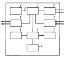
- the controller unit incorporates a microprocessor 1 which in a first mode is used for establishing a reference or calibration relationship for each transducer incorporated in the unit or effectively integrally associated with the controller unit, between the outputs thereof and input data characteristic of known levels of the parameter with which a transducer under calibration is associated; and which in a second mode is used for real time transducer temperature correction of transducer output.
- a microprocessor 1 which in a first mode is used for establishing a reference or calibration relationship for each transducer incorporated in the unit or effectively integrally associated with the controller unit, between the outputs thereof and input data characteristic of known levels of the parameter with which a transducer under calibration is associated; and which in a second mode is used for real time transducer temperature correction of transducer output.
- the calibration relationships established by the microprocessor are stored in a non-volatile store 2, connected with the microprocessor by way of a data and control signal bus 3.
- the unit includes a control signal and input data port 4 connecting with the microprocessor 1.
- This port is intended to provide access to the microprocessor for control signals to select the operating mode, and to control the calibration process by providing information describing the mechanical stimulus (input) being applied.
- the processing is able to establish the relationship between the transducer output and the mechanical input.
- transducer 6 is a strain gauge accelerometer and the transducer 7 is a piezo-electrical accelerometer.
- the accelerometers are mechanically attached to whatever member, article, etc., the acceleration of which it is desired to measure and/or monitor.
- the transducer 8 is formed by a thermistor whose purpose is to sense the temperature of the transducers 6 and 7.
- microprocessor 1 has associated input buffer circuits 9 and output driver circuits 10
- the various transducers 6,7 and 8 are regarded as being an integral part of the electronic controller unit so that the latter can be regarded as an integral package of electronic control circuitry and transducer(s).
- the unit is tested for correctness of manufacture and operation.
- the unit is then calibrated in order establish calibration data in respect of transducer installation orientation etc., and also to establish the above mentioned temperature/transducer measurement parameter relationships or calibration map for the associated transducers.
- the latter is mounted into apparatus which is capable of subjecting the unit transducers to changes in the particular parameter involved.
- the apparatus is able to subject the control unit to known acceleration levels whilst at the same time subjecting the control unit to temperature changes though a range of values extending throughout the required temperature range of operation of the controller unit.
- the microprocessor 1 is set to its calibration mode by application of the requisite control signals to the input port 4.
- the controller unit is then subjected to the above mentioned known acceleration force levels so that the transducers 6 and 7 are subjected to known accelerations.
- the transducers produce output signals which are uncorrected for temperature conditions. These uncorrected outputs are applied to the converter 5 and thus subsequently applied to the microprocessor as digital signals.
- the thermistor 8 will produce its output and this output will be characteristic of the temperature conditions in the immediate vicinity of the thermistor. In practice, it is arranged that the thermistor is as close as possible to the transducers 6 and 7 so as to avoid introduction of error due to the fact that the transducers 6 and 7 could be at a temperature different from that prevailing at the thermistor. If desired, each transducer 6 or 7 could have a thermistor uniquely associated therewith.
- the microprocessor 1 thus receives three main forms of signals; firstly, signals related to i.e., a function of known acceleration force levels; secondly, signals related to the actual output of the transducers 6 and 7; and thirdly signals related to the thermistor output.
- the microprocessor is either firmwired or suitably programmed to be able to produce from these signals the calibration relationship relating thermistor reading and the real acceleration level to the instantaneous outputs of the transducers 6 and 7.
- the temperature is changed throughout said expected range whereby the microprocessor 1 receives a series of input values from the transducers 6 and 7, the thermistor, and the real acceleration level data and derives therefrom the calibration map.
- the temperature variation calibration thus derived is stored in the non-volatile memory 2.
- the transducer controller unit is subjected to a second calibration, which can be regarded as an In situ calibration, and which involves effecting measurements with the transducer installed at differing angles to the accelerating force direction.
- the electronic controller unit will incorporate a full calibration history with which the instantaneous output from a transducer 6 or 7 is compared so as to produce, during the active use of the transducers 6 and 7 outputs, corrected for all of the factors thought relevant.
- the electonic controller unit will be continuously monitoring the thermistor reading and using such reading and any other information considered relevant to ensure that the requisite correction factor is applied to the outputs of the associated accelerometers whereby the outputs from the electronic control unit are always corrected for whatever factors considered relevant.
- the controller unit of the invention can conveniently be regarded as a composite assembly or package which includes not only transducers but also a microprocessor for enabling establishing calibration relationships for the transducers which relationships are internally permanently stored in non-volitile memory i.e., in Read Only Memory devices and for enabling such stored relationships to be used for real time comparisons with instantaneous transducer outputs whereby the actual outputs produced by the controller are suitably compensated for ambient temperature values
- the electronic controller unit of the invention provides an arrangement whereby the outputs from the transducers incorporated in the unit are temperature corrected for temperature and any other factors considered relevant.
- the accelerometers of the controller unit will be mounted to those parts of a motor vehicle suspension system whose movements are to be monitored and controlled.
Landscapes
- General Physics & Mathematics (AREA)
- Physics & Mathematics (AREA)
- Vehicle Body Suspensions (AREA)
- Electrophonic Musical Instruments (AREA)
- Burglar Alarm Systems (AREA)
- Sink And Installation For Waste Water (AREA)
- Contacts (AREA)
- Electrotherapy Devices (AREA)
- Control Of Motors That Do Not Use Commutators (AREA)
- Oscillators With Electromechanical Resonators (AREA)
- Indication And Recording Devices For Special Purposes And Tariff Metering Devices (AREA)
- Selective Calling Equipment (AREA)
- Supplying Of Containers To The Packaging Station (AREA)
- Control And Other Processes For Unpacking Of Materials (AREA)
Claims (5)
des moyens de détection de la valeur de la température ambiante instantanée au voisinage du transducteur associé durant le mode de correction et durant le mode de calibrage ;
des moyens pour appliquer, sous forme de signaux digitaux, la sortie de chacun des transducteurs au microprocesseur, permettant ainsi une correction selon une relation stockée de calibrage associée en rapport avec les valeurs de la température ambiante et fournissant un signal de sortie corrigé ; et
une mémoire non-volatile pour stocker les données de calibrage ; dans laquelle le microprocesseur possède un port d'entrée d'un signal de contrôle et de données connecté au microprocesseur, ledit port d'entrée étant conçu pour fournir un accès au microprocesseur à des signaux de contrôle permettant de choisir entre le mode de correction et le mode de calibrage, dans lequel les signaux correspondant à un stimulus mécanique, à une sortie de transducteur, et aux valeurs de la température ambiante sont reçus, la relation de calibrage étant établie pour la plage de températures dans laquelle le transducteur calibré est le plus susceptible de fonctionner.
Priority Applications (1)
| Application Number | Priority Date | Filing Date | Title |
|---|---|---|---|
| AT88908736T ATE79671T1 (de) | 1987-10-05 | 1988-10-05 | Elektronische steueranordnung. |
Applications Claiming Priority (2)
| Application Number | Priority Date | Filing Date | Title |
|---|---|---|---|
| GB8723339 | 1987-10-05 | ||
| GB878723339A GB8723339D0 (en) | 1987-10-05 | 1987-10-05 | Transducer control circuits |
Publications (2)
| Publication Number | Publication Date |
|---|---|
| EP0380552A1 EP0380552A1 (fr) | 1990-08-08 |
| EP0380552B1 true EP0380552B1 (fr) | 1992-08-19 |
Family
ID=10624805
Family Applications (1)
| Application Number | Title | Priority Date | Filing Date |
|---|---|---|---|
| EP88908736A Expired EP0380552B1 (fr) | 1987-10-05 | 1988-10-05 | Unite de commande electronique |
Country Status (8)
| Country | Link |
|---|---|
| US (1) | US5038306A (fr) |
| EP (1) | EP0380552B1 (fr) |
| JP (1) | JPH03501882A (fr) |
| AT (1) | ATE79671T1 (fr) |
| AU (1) | AU2537788A (fr) |
| DE (1) | DE3873927T2 (fr) |
| GB (2) | GB8723339D0 (fr) |
| WO (1) | WO1989003019A1 (fr) |
Families Citing this family (16)
| Publication number | Priority date | Publication date | Assignee | Title |
|---|---|---|---|---|
| JPH03134552A (ja) * | 1989-10-20 | 1991-06-07 | Hitachi Ltd | 自己較正機能付検出装置 |
| JPH0830710B2 (ja) * | 1990-03-08 | 1996-03-27 | 本田技研工業株式会社 | 角速度検出器 |
| US5321638A (en) * | 1990-04-30 | 1994-06-14 | Witney Keith C | Calibrated sensor systems and methods of manufacturing same |
| IT1255183B (it) * | 1992-06-26 | 1995-10-20 | Luciano Manenti | Trasduttore remoto indirizzabile con taratura automatica e compensazione digitale |
| FR2694095B1 (fr) * | 1992-07-21 | 1994-11-18 | Sextant Avionique | Procédé et dispositif pour la correction des erreurs d'acquisition de grandeurs électriques par autocalibration initiale et correction par module de compensation thermique. |
| DE4228893B4 (de) * | 1992-08-29 | 2004-04-08 | Robert Bosch Gmbh | System zur Beeinflussung der Fahrdynamik eines Kraftfahrzeugs |
| FR2696552B1 (fr) * | 1992-10-02 | 1994-12-02 | Telecommunications Sa | Procédé et dispositif numérique de linéarisation de grandeur électrique. |
| CA2107624C (fr) * | 1992-10-05 | 2002-01-08 | Stephen G. Seberger | Etalonnage d'un convertisseur electro-pneumatique |
| US5440237A (en) * | 1993-06-01 | 1995-08-08 | Incontrol Solutions, Inc. | Electronic force sensing with sensor normalization |
| DE4340719A1 (de) * | 1993-11-30 | 1995-06-01 | Siemens Ag | Schaltungsanordnung zum Auswerten der Signale eines Giergeschwindigkeitssensors |
| JP2003519371A (ja) * | 2000-01-05 | 2003-06-17 | コンティネンタル・テーベス・アクチエンゲゼルシヤフト・ウント・コンパニー・オッフェネ・ハンデルスゲゼルシヤフト | センサ信号の補正値テーブルを作成する方法とセンサモジュール |
| US6443416B1 (en) | 2001-09-26 | 2002-09-03 | The United States Of America As Represented By The Secretary Of The Navy | Piezoelectrically controlled vibration reducing mount system |
| DE10207228A1 (de) * | 2002-02-21 | 2003-09-04 | Bosch Gmbh Robert | Verfahren zur Kalibrierung eines Sensors und Schaltungsanordnung zum Betreiben eines Sensors |
| JP2009507215A (ja) * | 2005-09-02 | 2009-02-19 | コンティネンタル・テーベス・アクチエンゲゼルシヤフト・ウント・コンパニー・オッフェネ・ハンデルスゲゼルシヤフト | センサ、特にヨーレート・センサを較正する方法 |
| US9316667B2 (en) | 2012-11-14 | 2016-04-19 | Bose Corporation | Accelerometer leveling in an actively controlled vehicle suspension |
| US12510556B2 (en) * | 2023-04-11 | 2025-12-30 | Atlantic Inertial Systems, Inc. | Micro-electrical-mechanical-systems (MEMS) accelerometer systems |
Family Cites Families (25)
| Publication number | Priority date | Publication date | Assignee | Title |
|---|---|---|---|---|
| GB1495278A (en) * | 1975-06-13 | 1977-12-14 | Avery Ltd W & T | Compensation for weight-independent parameters in weighin |
| US4192005A (en) * | 1977-11-21 | 1980-03-04 | Kulite Semiconductor Products, Inc. | Compensated pressure transducer employing digital processing techniques |
| CA1102829A (fr) * | 1978-07-27 | 1981-06-09 | Herbert E. Gladish | Traduction non-disponible |
| US4399515A (en) * | 1981-03-31 | 1983-08-16 | The United States Of America As Represented By The Administrator Of The National Aeronautics And Space Administration | Self-correcting electronically scanned pressure sensor |
| US4490803A (en) * | 1981-04-03 | 1984-12-25 | Lucas Industries Limited | Temperature compensation of a resistance bridge circuit |
| DE3116690C2 (de) * | 1981-04-28 | 1983-09-15 | Rohde & Schwarz GmbH & Co KG, 8000 München | Einrichtung zum Messen von physikalischen Grössen |
| JPS58114199A (ja) * | 1981-12-26 | 1983-07-07 | 株式会社東芝 | 2線式圧力差圧伝送器 |
| US4613115A (en) * | 1982-08-30 | 1986-09-23 | Gas Spring Company, Division Of Fichtel & Sachs Industries, Inc. | Temperature compensated gas spring |
| US4478527A (en) * | 1982-12-02 | 1984-10-23 | General Signal Corporation | Temperature compensation for zero and span changes in a measurement circuit |
| JPS59137207A (ja) * | 1983-01-24 | 1984-08-07 | Nissan Motor Co Ltd | サスペンシヨン装置 |
| US4522072A (en) * | 1983-04-22 | 1985-06-11 | Insouth Microsystems, Inc. | Electromechanical transducer strain sensor arrangement and construction |
| US4633422A (en) * | 1983-07-26 | 1986-12-30 | Cincinnati Electronics Corporation | Apparatus for and method of compensating for variations due to aging |
| US4611304A (en) * | 1983-07-27 | 1986-09-09 | Sundstrand Data Control, Inc. | Transducer memory circuit |
| US4542638A (en) * | 1983-09-16 | 1985-09-24 | Fellows Corporation | Automatic calibration of sensor circuits in gear shapers |
| US4592002A (en) * | 1983-12-13 | 1986-05-27 | Honeywell Inc. | Method of digital temperature compensation and a digital data handling system utilizing the same |
| US4734873A (en) * | 1984-02-02 | 1988-03-29 | Honeywell Inc. | Method of digital process variable transmitter calibration and a process variable transmitter system utilizing the same |
| JP2579143B2 (ja) * | 1984-02-02 | 1997-02-05 | ハネウエル・インコーポレーテッド | プロセス変数センサのディジタル補正の方法およびそのためのプロセス変数発信器 |
| DE3427743A1 (de) * | 1984-07-27 | 1986-02-06 | Keller AG für Druckmeßtechnik, Winterthur | Verfahren zur temperaturkompensation und messschaltung hierfuer |
| DE3531118A1 (de) * | 1985-08-30 | 1987-03-12 | Micro Epsilon Messtechnik | Verfahren zur fehlerkompensation fuer messwertaufnehmer mit nicht linearen kennlinien, sowie anordnung zur durchfuehrung des verfahrens |
| JPS62294927A (ja) * | 1986-06-13 | 1987-12-22 | Yamato Scale Co Ltd | 力測定装置 |
| GB2197957B (en) * | 1986-11-22 | 1990-10-17 | Motorola Ltd | Sensor systems |
| GB8705192D0 (en) * | 1987-03-05 | 1987-04-08 | Secr Defence | Transducer signal conditioner |
| US4967385A (en) * | 1987-05-29 | 1990-10-30 | J.I. Case Company | Electronic control system for powershift transmission |
| CA1293568C (fr) * | 1987-10-01 | 1991-12-24 | Romet Limited | Correcteurs de debit electroniques |
| DE3737760A1 (de) * | 1987-11-06 | 1989-05-18 | Pfister Gmbh | Verfahren zum optimieren der fahreigenschaft von fahrzeugen |
-
1987
- 1987-10-05 GB GB878723339A patent/GB8723339D0/en active Pending
-
1988
- 1988-10-05 GB GB8823409A patent/GB2210695B/en not_active Expired - Lifetime
- 1988-10-05 AU AU25377/88A patent/AU2537788A/en not_active Abandoned
- 1988-10-05 EP EP88908736A patent/EP0380552B1/fr not_active Expired
- 1988-10-05 AT AT88908736T patent/ATE79671T1/de not_active IP Right Cessation
- 1988-10-05 WO PCT/GB1988/000822 patent/WO1989003019A1/fr not_active Ceased
- 1988-10-05 JP JP63508161A patent/JPH03501882A/ja active Pending
- 1988-10-05 DE DE8888908736T patent/DE3873927T2/de not_active Revoked
- 1988-10-05 US US07/469,430 patent/US5038306A/en not_active Expired - Fee Related
Also Published As
| Publication number | Publication date |
|---|---|
| EP0380552A1 (fr) | 1990-08-08 |
| DE3873927T2 (de) | 1993-03-25 |
| JPH03501882A (ja) | 1991-04-25 |
| ATE79671T1 (de) | 1992-09-15 |
| AU2537788A (en) | 1989-04-18 |
| WO1989003019A1 (fr) | 1989-04-06 |
| GB2210695A (en) | 1989-06-14 |
| US5038306A (en) | 1991-08-06 |
| GB8823409D0 (en) | 1988-11-09 |
| GB2210695B (en) | 1992-07-01 |
| GB8723339D0 (en) | 1987-11-11 |
| DE3873927D1 (de) | 1992-09-24 |
Similar Documents
| Publication | Publication Date | Title |
|---|---|---|
| EP0380552B1 (fr) | Unite de commande electronique | |
| US7478001B2 (en) | Systems and methods for temperature-compensated measuring of a load | |
| US5321638A (en) | Calibrated sensor systems and methods of manufacturing same | |
| US6818842B2 (en) | Seat foam humidity compensation for vehicle seat occupant weight detection system | |
| US7650253B2 (en) | Accelerometer and method for error compensation | |
| US9221679B2 (en) | Compensation and calibration for MEMS devices | |
| US5440913A (en) | Electronic device for safeguarding occupants of a vehicle and method for testing the same | |
| US20030109939A1 (en) | Method for establishing a table of correction values and sensor signal and a sensor module | |
| EP0534645A1 (fr) | Dispositifs et procédé pour calibrer d'un module de commande de suspension | |
| US9927266B2 (en) | Multi-chip device with temperature control element for temperature calibration | |
| JPS59660A (ja) | センサ信号の温度補償方法 | |
| CN100595530C (zh) | 称重装置,特别是多轨迹称重装置 | |
| US5086656A (en) | Method and apparatus for calculating the axle load of a vehicle | |
| CN119301431A (zh) | 用于补偿加速度的膜片传感器以及相应的运行方法 | |
| JPH11500218A (ja) | 圧力変換器例えば自動車における側面衝突を検出するための圧力変換器 | |
| US7359818B2 (en) | Sensor apparatus, control system having the same and offset correction method | |
| US20110041614A1 (en) | Circuit for a micromechanical structure-borne sound sensor and method for operating a micromechanical structure-borne sound sensor | |
| US6230565B1 (en) | Pressure-compensated transducers, pressure-compensated accelerometers, force-sensing methods, and acceleration-sensing methods | |
| US5698785A (en) | Self-compensating accelerometer | |
| US5903855A (en) | Acceleration sensor | |
| EP0376995B1 (fr) | Detecteur d'acceleration | |
| US5295387A (en) | Active resistor trimming of accelerometer circuit | |
| JPH0735646A (ja) | リーフスプリングの特性測定装置 | |
| US6028371A (en) | Process for direction-selective orientation of a passive safety device | |
| US5369305A (en) | Safety device |
Legal Events
| Date | Code | Title | Description |
|---|---|---|---|
| PUAI | Public reference made under article 153(3) epc to a published international application that has entered the european phase |
Free format text: ORIGINAL CODE: 0009012 |
|
| 17P | Request for examination filed |
Effective date: 19900404 |
|
| AK | Designated contracting states |
Kind code of ref document: A1 Designated state(s): AT BE CH DE FR GB IT LI LU NL SE |
|
| 17Q | First examination report despatched |
Effective date: 19910228 |
|
| GRAA | (expected) grant |
Free format text: ORIGINAL CODE: 0009210 |
|
| AK | Designated contracting states |
Kind code of ref document: B1 Designated state(s): AT BE CH DE FR GB IT LI LU NL SE |
|
| PG25 | Lapsed in a contracting state [announced via postgrant information from national office to epo] |
Ref country code: IT Free format text: LAPSE BECAUSE OF FAILURE TO SUBMIT A TRANSLATION OF THE DESCRIPTION OR TO PAY THE FEE WITHIN THE PRESCRIBED TIME-LIMIT;WARNING: LAPSES OF ITALIAN PATENTS WITH EFFECTIVE DATE BEFORE 2007 MAY HAVE OCCURRED AT ANY TIME BEFORE 2007. THE CORRECT EFFECTIVE DATE MAY BE DIFFERENT FROM THE ONE RECORDED. Effective date: 19920819 Ref country code: AT Effective date: 19920819 Ref country code: NL Effective date: 19920819 Ref country code: SE Free format text: LAPSE BECAUSE OF FAILURE TO SUBMIT A TRANSLATION OF THE DESCRIPTION OR TO PAY THE FEE WITHIN THE PRESCRIBED TIME-LIMIT Effective date: 19920819 Ref country code: BE Effective date: 19920819 |
|
| REF | Corresponds to: |
Ref document number: 79671 Country of ref document: AT Date of ref document: 19920915 Kind code of ref document: T |
|
| REF | Corresponds to: |
Ref document number: 3873927 Country of ref document: DE Date of ref document: 19920924 |
|
| PG25 | Lapsed in a contracting state [announced via postgrant information from national office to epo] |
Ref country code: LU Free format text: LAPSE BECAUSE OF NON-PAYMENT OF DUE FEES Effective date: 19921031 |
|
| ET | Fr: translation filed | ||
| NLV1 | Nl: lapsed or annulled due to failure to fulfill the requirements of art. 29p and 29m of the patents act | ||
| PLBI | Opposition filed |
Free format text: ORIGINAL CODE: 0009260 |
|
| PLBI | Opposition filed |
Free format text: ORIGINAL CODE: 0009260 |
|
| 26 | Opposition filed |
Opponent name: CARL SCHENCK AG Effective date: 19930429 |
|
| 26 | Opposition filed |
Opponent name: CARL SCHENCK AG Effective date: 19930429 Opponent name: HOTTINGER BALDWIN MESSTECHNIK GMBH PATENTABTEILUNG Effective date: 19930514 |
|
| PGFP | Annual fee paid to national office [announced via postgrant information from national office to epo] |
Ref country code: DE Payment date: 19931005 Year of fee payment: 6 |
|
| PGFP | Annual fee paid to national office [announced via postgrant information from national office to epo] |
Ref country code: FR Payment date: 19931026 Year of fee payment: 6 |
|
| PGFP | Annual fee paid to national office [announced via postgrant information from national office to epo] |
Ref country code: GB Payment date: 19931105 Year of fee payment: 6 |
|
| PGFP | Annual fee paid to national office [announced via postgrant information from national office to epo] |
Ref country code: CH Payment date: 19931119 Year of fee payment: 6 |
|
| PG25 | Lapsed in a contracting state [announced via postgrant information from national office to epo] |
Ref country code: GB Effective date: 19941005 |
|
| PG25 | Lapsed in a contracting state [announced via postgrant information from national office to epo] |
Ref country code: CH Free format text: LAPSE BECAUSE OF NON-PAYMENT OF DUE FEES Effective date: 19941031 Ref country code: LI Free format text: LAPSE BECAUSE OF NON-PAYMENT OF DUE FEES Effective date: 19941031 |
|
| GBPC | Gb: european patent ceased through non-payment of renewal fee |
Effective date: 19941005 |
|
| REG | Reference to a national code |
Ref country code: CH Ref legal event code: PL |
|
| REG | Reference to a national code |
Ref country code: FR Ref legal event code: ST |
|
| RDAG | Patent revoked |
Free format text: ORIGINAL CODE: 0009271 |
|
| STAA | Information on the status of an ep patent application or granted ep patent |
Free format text: STATUS: PATENT REVOKED |
|
| 27W | Patent revoked |
Effective date: 19950603 |