EP0380455B1 - Klimaanlage für ein Kraftfahrzeug - Google Patents
Klimaanlage für ein Kraftfahrzeug Download PDFInfo
- Publication number
- EP0380455B1 EP0380455B1 EP90830014A EP90830014A EP0380455B1 EP 0380455 B1 EP0380455 B1 EP 0380455B1 EP 90830014 A EP90830014 A EP 90830014A EP 90830014 A EP90830014 A EP 90830014A EP 0380455 B1 EP0380455 B1 EP 0380455B1
- Authority
- EP
- European Patent Office
- Prior art keywords
- shutter
- air
- shutters
- aperture
- conditioning system
- Prior art date
- Legal status (The legal status is an assumption and is not a legal conclusion. Google has not performed a legal analysis and makes no representation as to the accuracy of the status listed.)
- Expired
Links
Images


Classifications
-
- B—PERFORMING OPERATIONS; TRANSPORTING
- B60—VEHICLES IN GENERAL
- B60H—ARRANGEMENTS OF HEATING, COOLING, VENTILATING OR OTHER AIR-TREATING DEVICES SPECIALLY ADAPTED FOR PASSENGER OR GOODS SPACES OF VEHICLES
- B60H1/00—Heating, cooling or ventilating devices
- B60H1/00642—Control systems or circuits; Control members or indication devices for heating, cooling or ventilating devices
- B60H1/00814—Control systems or circuits characterised by their output, for controlling particular components of the heating, cooling or ventilating installation
- B60H1/00821—Control systems or circuits characterised by their output, for controlling particular components of the heating, cooling or ventilating installation the components being ventilating, air admitting or air distributing devices
- B60H1/00835—Damper doors, e.g. position control
- B60H1/00857—Damper doors, e.g. position control characterised by the means connecting the initiating means, e.g. control lever, to the damper door
Definitions
- the present invention relates to an air-conditioning system for motor vehicles, comprising a hollow support structure with apertures for the passage of air, an operating member which is supported for rotation by the structure, and at least one pair of shutters pivoted to the structure and operated by the operating member through respective transmission means.
- each choking or closure shutter has a respective operative member. This makes the production of the system more complicated while at the same time leaving it to the user to achieve the air-flow distribution in the passenger compartment. This optimisation is not easy and often requires repeated manual operation of the operating levers of the system.
- the object of the present invention is to provide an air-conditioning system of the type specified at the beginning of the description which does not have the above disadvantages and which also ensures the optimum distribution of the air flow without requiring particular attention by the user.
- the first shutter which is adapted to close and/or choke a first aperture in the support structure, has a second aperture which is adapted to be closed and/or choked by a second shutter which is pivoted to the first shutter about a common articulation axis
- the transmission means comprising a rod which is pivoted to the rotatable operating member and to the second shutter and which is provided with a device for connecting it to the first shutter, the device being adapted to operate when the operating member is in a predetermined angular position, and resilient means being interposed between the first and second shutters to keep the first shutter closed when the connecting device is in its inoperative condition.
- the connecting device preferably includes first and second levers which are pivoted to each other like a toggle, and to the rod and to the first shutter respectively, one of the levers having an abutment for preventing the relative pivoting of the levers beyond a predetermined angle.
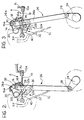
- the hollow structure of a motor-vehicle air-conditioning system indicated S has a substantially rectangular aperture A.
- a first shutter 10 for closing or choking the air flow through the aperture A is articulated to the structure S about a horizontal axis X-X and has an end edge 10a which is covered with elastomeric material in order to ensure optimal sealing with an edge A1 of the aperture A.
- the first shutter 10 which is rectangular in shape, has a rectangular aperture 12 for cooperating with a second shutter 14 which is articulated to the support structure S coaxially with the first shutter 10.
- the aperture 12 of the latter has a flange 16 on its edge opposite the articulation axis X-X, the flange having a circular cross-section with its centre of rotation situated on the axis X-X.
- the second shutter 14 has an auxiliary flange 18 on its edge opposite to the articulation axis X-X, the shape of the flange corresponding to that of the flange 16 of the first shutter 10 so that it can slide coaxially on the latter, ensuring sufficient air sealing.
- a pin spring 20, whose function will become clear from the following description, is interposed between the second shutter 14 and an abutment portion 16a of the flange 16.
- An operating system is provided for operating the first and second shutters 10 and 14 respectively.
- the system includes an operating member 24, which is articulated to the structure S about an axis Y-Y substantially parallel to the articulation axis X-X of the shutters, and a connecting rod 26 which is articulated at 28 to the operating member 24.
- the rod 26 has an end 26a articulated at 30 to the side of the second shutter 14. The rotation of the operation member 24 thus rotates the second shutter 14 directly about the axis X-X.
- a toggle device 32 comprising a pair of levers 32a and 32b which are articulated to each other at 34, is interposed between the first shutter 10 and an intermediate portion 26b of the rod 26.
- the first lever 32a is also articulated at 36 to the intermediate portion 26b of the rod 26 whilst the second lever 32b is articulated at 38 to the first shutter 10 beside its rectangular aperture 12.
- the first lever 32a has an end abutment 40 for cooperating with an edge 32c of the second lever 32b in order to prevent the two levers of the toggle device 32 from pivoting beyond a predetermined angle.
- FIG. 2 shows the configuration in which both of the shutters 10 and 14 are closed over the apertures A and 12.
- the first shutter 10 is kept closed by means of the force exerted by the spring 20 which, by cooperating with the second shutter 14 which is kept in position by the rod 26, urges the shutter 10 into abutment with the edge A1 of the aperture A.
Landscapes
- Physics & Mathematics (AREA)
- Thermal Sciences (AREA)
- Engineering & Computer Science (AREA)
- Mechanical Engineering (AREA)
- Air-Flow Control Members (AREA)
Claims (5)
Applications Claiming Priority (2)
| Application Number | Priority Date | Filing Date | Title |
|---|---|---|---|
| IT8967030A IT1232410B (it) | 1989-01-20 | 1989-01-20 | Impianto di climatizzazione per autoveicoli |
| IT6703089 | 1989-01-20 |
Publications (2)
| Publication Number | Publication Date |
|---|---|
| EP0380455A1 EP0380455A1 (de) | 1990-08-01 |
| EP0380455B1 true EP0380455B1 (de) | 1992-04-01 |
Family
ID=11299027
Family Applications (1)
| Application Number | Title | Priority Date | Filing Date |
|---|---|---|---|
| EP90830014A Expired EP0380455B1 (de) | 1989-01-20 | 1990-01-16 | Klimaanlage für ein Kraftfahrzeug |
Country Status (4)
| Country | Link |
|---|---|
| EP (1) | EP0380455B1 (de) |
| DE (1) | DE69000048D1 (de) |
| ES (1) | ES2031019T3 (de) |
| IT (1) | IT1232410B (de) |
Families Citing this family (1)
| Publication number | Priority date | Publication date | Assignee | Title |
|---|---|---|---|---|
| FR2703303B1 (fr) * | 1993-04-01 | 1995-06-23 | Valeo Thermique Habitacle | Dispositif de commande d'un volet pivotant procurant une position stable. |
Family Cites Families (3)
| Publication number | Priority date | Publication date | Assignee | Title |
|---|---|---|---|---|
| FR2238105A1 (en) * | 1973-07-20 | 1975-02-14 | Ferodo Sa | Vehicle heating and ventilation air distributor - two spring loaded closure flaps are controlled by cam lever |
| FR2480685A1 (fr) * | 1980-04-16 | 1981-10-23 | Ferodo Sa | Dispositif de commande de la circulation d'air dans une installation de chauffage ou de climatisation, notamment d'un habitacle de vehicule automobile |
| DE3112684C2 (de) * | 1981-03-31 | 1984-08-02 | Ford-Werke AG, 5000 Köln | Heiz- und Belüftungsanlage für Kraftfahrzeuge |
-
1989
- 1989-01-20 IT IT8967030A patent/IT1232410B/it active
-
1990
- 1990-01-16 ES ES199090830014T patent/ES2031019T3/es not_active Expired - Lifetime
- 1990-01-16 EP EP90830014A patent/EP0380455B1/de not_active Expired
- 1990-01-16 DE DE9090830014T patent/DE69000048D1/de not_active Expired - Lifetime
Also Published As
| Publication number | Publication date |
|---|---|
| DE69000048D1 (de) | 1992-05-07 |
| ES2031019T3 (es) | 1992-11-16 |
| IT8967030A0 (it) | 1989-01-20 |
| IT1232410B (it) | 1992-02-17 |
| EP0380455A1 (de) | 1990-08-01 |
Similar Documents
| Publication | Publication Date | Title |
|---|---|---|
| EP1375217B1 (de) | Belüftungsdüse | |
| CA2345865C (en) | Ceiling grille for rooftop air conditioner unit | |
| EP0810112A2 (de) | Düse zum Verteilen, Richten, Regulieren und Verschliessen von klimatisierter Luft in Kraftfahrzeugen | |
| EP0423778B1 (de) | Luftverteiler für Klimaanlage von Kraftfahrzeugen | |
| US7029390B2 (en) | Air vent for vehicle air ducting | |
| US5281049A (en) | Air direction control means for vehicle climate control means | |
| CN112297777A (zh) | 空气排出装置 | |
| AU752056B2 (en) | Air mix damper device and vehicle air conditioner | |
| EP0707992A1 (de) | Belüftungsdüse zur Abgabe und Richten von klimatisierter Luft in Kraftfahrzeugen | |
| US5569076A (en) | Oscillation fixed grille outlet | |
| EP0380455B1 (de) | Klimaanlage für ein Kraftfahrzeug | |
| US6126537A (en) | Blower unit for air conditioning system for automotive vehicles | |
| EP0330154A2 (de) | Vorrichtung für die gleichzeitige oder getrennte Betätigung von Regelventilen in Kraftfahrzeug-Klimatisierungsanlagen | |
| US6254175B1 (en) | Air vent system for door of automobile | |
| GB2129119A (en) | Ventilation port for an automobile passenger compartment | |
| US4541611A (en) | Arrangement for controlling an air duct | |
| JP2000335235A (ja) | 自動車用レジスタの奥側風向調節機構 | |
| EP0342679B1 (de) | Vom Fahrzeuginneren betätigbare Kraftstoff-Einfülleinrichtung | |
| EP0172869B1 (de) | Betätigungsvorrichtung für ein lüftungsdach eines kraftfahrzeuges | |
| US4597415A (en) | Integrated lever and live spring valve | |
| US5595091A (en) | Restraint mechanism for a control lever | |
| US5195926A (en) | Flap arrangement | |
| EP0551754B1 (de) | Luftverteilungseinheit | |
| GB2328012A (en) | Distributing air for the passenger compartment of a vehicle. | |
| JP2588007Y2 (ja) | 風向き調整用水平羽根の連杆外れ防止構造 |
Legal Events
| Date | Code | Title | Description |
|---|---|---|---|
| PUAI | Public reference made under article 153(3) epc to a published international application that has entered the european phase |
Free format text: ORIGINAL CODE: 0009012 |
|
| AK | Designated contracting states |
Kind code of ref document: A1 Designated state(s): DE ES FR GB SE |
|
| 17P | Request for examination filed |
Effective date: 19910122 |
|
| 17Q | First examination report despatched |
Effective date: 19910529 |
|
| GRAA | (expected) grant |
Free format text: ORIGINAL CODE: 0009210 |
|
| AK | Designated contracting states |
Kind code of ref document: B1 Designated state(s): DE ES FR GB SE |
|
| REF | Corresponds to: |
Ref document number: 69000048 Country of ref document: DE Date of ref document: 19920507 |
|
| ET | Fr: translation filed | ||
| REG | Reference to a national code |
Ref country code: ES Ref legal event code: FG2A Ref document number: 2031019 Country of ref document: ES Kind code of ref document: T3 |
|
| PLBE | No opposition filed within time limit |
Free format text: ORIGINAL CODE: 0009261 |
|
| STAA | Information on the status of an ep patent application or granted ep patent |
Free format text: STATUS: NO OPPOSITION FILED WITHIN TIME LIMIT |
|
| 26N | No opposition filed | ||
| EAL | Se: european patent in force in sweden |
Ref document number: 90830014.8 |
|
| PGFP | Annual fee paid to national office [announced via postgrant information from national office to epo] |
Ref country code: SE Payment date: 20011130 Year of fee payment: 13 |
|
| PGFP | Annual fee paid to national office [announced via postgrant information from national office to epo] |
Ref country code: GB Payment date: 20011218 Year of fee payment: 13 Ref country code: ES Payment date: 20011218 Year of fee payment: 13 |
|
| PGFP | Annual fee paid to national office [announced via postgrant information from national office to epo] |
Ref country code: DE Payment date: 20011219 Year of fee payment: 13 |
|
| REG | Reference to a national code |
Ref country code: GB Ref legal event code: IF02 |
|
| PGFP | Annual fee paid to national office [announced via postgrant information from national office to epo] |
Ref country code: FR Payment date: 20020131 Year of fee payment: 13 |
|
| PG25 | Lapsed in a contracting state [announced via postgrant information from national office to epo] |
Ref country code: GB Free format text: LAPSE BECAUSE OF NON-PAYMENT OF DUE FEES Effective date: 20030116 |
|
| PG25 | Lapsed in a contracting state [announced via postgrant information from national office to epo] |
Ref country code: SE Free format text: LAPSE BECAUSE OF NON-PAYMENT OF DUE FEES Effective date: 20030117 Ref country code: ES Free format text: LAPSE BECAUSE OF NON-PAYMENT OF DUE FEES Effective date: 20030117 |
|
| PG25 | Lapsed in a contracting state [announced via postgrant information from national office to epo] |
Ref country code: DE Free format text: LAPSE BECAUSE OF NON-PAYMENT OF DUE FEES Effective date: 20030801 |
|
| EUG | Se: european patent has lapsed | ||
| GBPC | Gb: european patent ceased through non-payment of renewal fee | ||
| PG25 | Lapsed in a contracting state [announced via postgrant information from national office to epo] |
Ref country code: FR Free format text: LAPSE BECAUSE OF NON-PAYMENT OF DUE FEES Effective date: 20030930 |
|
| REG | Reference to a national code |
Ref country code: FR Ref legal event code: ST |
|
| REG | Reference to a national code |
Ref country code: ES Ref legal event code: FD2A Effective date: 20030117 |