EP0378166A2 - Verfahren und Vorrichtung zur Optimierung des stufenweisen Kristallisierens für die Wasserreinigung - Google Patents
Verfahren und Vorrichtung zur Optimierung des stufenweisen Kristallisierens für die Wasserreinigung Download PDFInfo
- Publication number
- EP0378166A2 EP0378166A2 EP90100365A EP90100365A EP0378166A2 EP 0378166 A2 EP0378166 A2 EP 0378166A2 EP 90100365 A EP90100365 A EP 90100365A EP 90100365 A EP90100365 A EP 90100365A EP 0378166 A2 EP0378166 A2 EP 0378166A2
- Authority
- EP
- European Patent Office
- Prior art keywords
- water
- ice
- freeze
- chamber
- layer
- Prior art date
- Legal status (The legal status is an assumption and is not a legal conclusion. Google has not performed a legal analysis and makes no representation as to the accuracy of the status listed.)
- Withdrawn
Links
Images


Classifications
-
- C—CHEMISTRY; METALLURGY
- C02—TREATMENT OF WATER, WASTE WATER, SEWAGE, OR SLUDGE
- C02F—TREATMENT OF WATER, WASTE WATER, SEWAGE, OR SLUDGE
- C02F1/00—Treatment of water, waste water, or sewage
- C02F1/22—Treatment of water, waste water, or sewage by freezing
Definitions
- This invention relates to batch purification of water by freezing the water into ice and by melting the ice, and more particularly to the method and means for optimizing the operating parameters, including the surface area of the evaporator, the freezing time, the thickness of ice, the depth of the batch volume of water to be purified, the volumetric capacity, the cost per gallon, and the like.
- Certain known water purification systems use freeze chambers and dynamic conditions to continuously form ice crystals in or from chilled water, and then to segregate the ice crystals from the chilled water for separate processing.
- volumetric capacity the quantity of water purified by the process (i.e., volumetric capacity) was considered to be related to the compressor capacity, or to the refrigerant evaporation temperature, or to the thermal conductivity of ice, without appropriate consideration given to optimizing the operating efficiency of the system.
- optimum configurations are set forth for a single- or multiple-chamber batch purification system operating on the freeze crystallization of water and the melting of the resulting ice.
- the optimum operating conditions established according to the present invention consider the surface area and temperature of the freeze plate, the freeze and melt times, the thickness of ice layer, the depth of the volume of chilled water in which an ice layer is formed, and the like.
- the locus of optimum operating conditions is established for such variables as compressor capacity, and allowable freeze and melt times to define the operating conditions for a small, efficient batch-processing water purifier.
- a volume of impure water is confined in a chamber wherein heat is extracted from the water, preferably at a boundary surface of the volume of water, in order to form a layer of ice in situ.
- the unfrozen portion of the volume of water with increased impurity concentration is then drained away and the layer of ice is then melted to yield a volume of purified water.
- Successive operations through these cycles yield a daily volume of purified water that is dependent upon several of the factors referred to above.
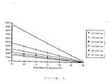
- the heat flux through a layer of ice is illustrated in Figure 2 plotted as a function of refrigerant evaporation temperature for various thicknesses of ice. From the chart of Figure 2, it should be noted that heat flux through a layer of ice is highest for the thinnest layer and lowest for the thickest layer. Stated differently, it should be noted that the heat flux through the layer of ice diminishes as the layer thickens, thus leading to reduced build-up of ice volume per unit time for given compressor operating conditions.
- a compressor Since a compressor has a given heat-pumping capacity (which depends upon the refrigerant evaporation temperature), and upon the thickness of the ice layer, then the surface area of the freeze plate through which the refrigerant circulates must be selected as a function of the compressor capacity.
- FIG. 3 there is shown a chart of heat flux through ice layers of various thicknesses as a function of refrigerant evaporation temperature, with the plot of compressor capacity for a given unit included in the illustrated family of curves. It should be noted from this chart that, at 0°F evaporation temperature, the given compressor unit does not have enough capacity to remove all of the heat that can be transferred through a layer of ice until it attains a thickness of about .6 inches. Thus, during initial operation, the rate of growth of the ice layer is limited by the heat-removal capacity of the compressor, and not by the rate at which heat can diffuse through the layer of ice.
- the average temperature of the freeze plate is considered not to be as low as the refrigerant evaporation temperature, even though the evaporation temperature is held substantially constant by such physical aspects of the system as the length of the conventional capillary tube, and the like. Therefore, it should be noted that for a practical system of the type described, there will be an initial operating period during which the compressor has insufficient capacity to remove the heat from water to be crystallized as rapidly as possible because the ice layer thus formed is initially very thin (i.e., very thermally conductive).
- freeze plate configuration of optimum area for forming and growing a volume of ice in a layer is preferred, for example, over a freeze plate configuration of smaller area for forming and growing a comparable volume of ice in a thicker, smaller layer. This is because the height of the ice-growing apparatus (as well as ice-formation times) increase with decreasing surface area of the freeze plate.
- the principal aspects for optimizing throughput in a batch purifier, once a compressor of given heat-removing capacity is selected, include: allowable freeze time; the refrigerant evaporation temperature; the freeze-plate surface area; volume of discarded water; and allowable melt time.
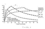
- Freeze time is the period of time for formation of the layer of ice of desired thickness and, as illustrated in the graph of Figure 4, there is an optimum time period for the reasons discussed above beyond which the throughput of purified water decreases.
- the chart of Figure 4 illustrates water production as a function of freeze time for various evaporation temperatures attainable with a given compressor unit. For a given compressor unit and a given evaporation temperature, there usually exist two distinct phases of ice formation, namely: a) ice formation limited initially by compressor capacity; and b) ice formation limited subsequently by the rate of thermal conduction through the ice layer. In terms of throughput of purified water, these phases are bounded by a distinct maximum point at an optimal freeze time, as illustrated in the graph of Figure 4.
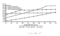
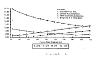
- the capital costs involved for throughput capacity may be optimized (i.e., at lowest cost per gallon per day), as illustrated in Figure 6, by considering the cost of the major component (i.e., the freeze plate) at, say, $10.00 per square foot of surface area, and by considering the production rates as a function of freeze plate area as illustrated in Figure 5. It should be noted that a point of minimum cost per gallon per day can be attained with a freeze plate of about 96 square inches (i.e., approximately 2/3 square foot), operating with refrigerant evaporation temperature at about 0°F.
- FIG. 7 there is shown a block schematic diagram of one embodiment of the present invention. Specifically, there is shown a compressor 11 which operates in a closed system 9 to circulate refrigerant through condenser 13 and expander 15 to the evaporator 17 including freeze plate 19, and then back to the compressor 11, all in conventional manner. Vaporization of the refrigerant within the evaporator 17 absorbs heat through the freeze plate 19 from water (and ice) 21 in the water vessel 23, and the refrigerant temperature is essentially established by the expander 15 which may include a conventional capillary or expansion valve.
- the water transfer system in the illustrated embodiment of the present invention includes the vessel 23 to which the feed water that is to be purified is supplied via the feedwater valve 25.
- the quantity of unfrozen waste water remaining in the vessel 23 after the requisite volume of ice is formed about the freeze plate 19 (and containing a higher concentration of residual impurities than the feedwater) is drained from the vessel via waste water drain valve 27.
- purified water which collects in vessel 23 as the volume of ice about freeze plate 19 is melted is drained away to storage 29 (or to direct consumption) via the purified water valve 21.
- a heater 33 may be disposed in contact with freeze plate 19 and/or with one or more of the boundary walls of vessel 23 to facilitate the rapid melting of the volume of ice formed about the freeze plate 19.
- the heater 33 may be an electrical heater, or the condenser of a refrigerant system operating in alternating time relationships with the freeze-cycle operation of system 9.
- heater 33 may include the condenser of another system for purifying water within another vessel (not shown), and operating in similar manner in alternating timed relationships of the freezing and melting operations of such two systems.
- other types of heaters such as infra-red sources, microwave, or the like, may also be used as the heater 33.
- the compressor 11, heater 33 and valves 25, 27, and 31 are operated in timed sequence by the controller 35.
- controller 35 activates the feedwater valve 25 to supply a quantity of water to be purified to vessel 23.
- the vessel is shaped closely approximate to the horizontal surface of the freeze plate 19 with a depth below the freeze plate 19 of approximately 1.1 to 3.0 times the expected thickness of a layer of ice beneath the freeze plate 19.
- the vessel 23 may be mounted to respond to weight of water to turn off the feedwater valve 25, and the evaporator 17 with freeze plate 19 may be resiliently mounted to accommodate expansion of ice within the confines of vessel 23, as well as to provide resilient bias of the ice layer against the freeze plate 19 to promote efficient heat transfer from the heater in the freeze plate 19 (when in operation) to the ice layer resiliently urged into contact therewith.
- the compressor 11 is activated by controller 35 to freeze the water in vessel 23 for a selected period of time, or until a selected volume of ice is formed about the freeze plate 19.
- the freeze time is the time from the first formation of ice at the surface of the freeze plate (or freeze cylinder in the case of a cylindrical vessel 23) until the compressor 11 is turned off, as determined by the controller 35. (The compressor 11 must also operate for a period of time to remove heat from the water before freezing begins).
- the total freeze time can be determined from the parameters of the system, as previously described. However, if a change in ambient temperature causes the condensing temperature to change, the compressor 11 capacity will change and the freeze time must be adjusted by the controller 35 to maintain the optimal throughput at the different ambient condition.
- the evaporation temperature is determined by the pressure drop induced by the flow of refrigerant through the expander 15 which may be either a fixed capillary tube or an expansion valve subject to control by controller 35.
- the freeze plate area 19, determined by the size of the evaporator 17, may be in the form of a plate located at the upper surface of the water 21 in the vessel 23, or in the form of a cylindrical vessel 23 with the freeze plate 19 forming the cylindrical walls.
- the recovery ratio is the ratio of the volume of purified water produced compared to the volume of feedwater required.
- the recovery ratio is determined by adjusting the volume of the vessel 23, either by changing the depth or by increasing the diameter of a cylindrical vessel.
- the ice crystal layer is grown vertically downward into the tray or vessel of water 21.
- a freeze plate 19 of a given surface area is in contact with the upper horizontal surface of the water and removes heat through the surface of the water 21 and through a horizontal ice-crystal layer that forms about the freeze plate 19.
- An alternate geometric configuration is a cylindrical vessel (for example of circular or rectangular cross-section) in which the ice-crystal layer is grown horizontally inward toward the center, with heat removal through the vertical sides of such cylinder.
- the impurities are concentrated in a column of water in the center of the cylinder (or beneath the plate 19) and are selectively drained via the wastewater drain valve 27 with the excess, impure water 21 that is not frozen then drained from the vessel 23 by activating valve 27 under control of controller 35. Thereafter, the heater 33 is activated to melt the volume of ice about the freeze plate 19. With valves 25 and 27 closed, the purified melt water is drained away to storage 29 through valve 31 that is activated by controller 35. Thereafter, with valves 27 and 31 closed, the feedwater valve 25 is activated to supply impure water to be purified 21 to the vessel 23 for operation through another freeze purification cycle, as previously described.
- the optimal thickness of ice layer is critical to obtaining the optimal purity and throughput of purified water, and occurs when the heat removed by the refrigeration system through the freeze plate is balanced by the heat that can be transferred through the ice layer.
- Equation 5 represents the compressor heat removal capacity (which is a function of evaporation temperature). while the right hand side of the equation represents the heat transfer through an ice layer of thickness ⁇ x and cross-sectional area A.
- q opt [2 ⁇ k ⁇ l ⁇ T ⁇ ln (r o ⁇ r i )] opt (Eq. 7) where, l is the length of the cylinder, r o is the outside radius of the cylinder, r i is the inside radius of the ice.
- the volumetric capacity of a freeze crystallization apparatus is equal to the volume of purified water produced in a batch divided by the cycle time required to prepare the batch.
- the cycle time includes the following components: ⁇ s the time required to remove heat from the water, ⁇ f the time required to freeze the ice, ⁇ m the time required to melt the ice, ⁇ o the time required for overhead, eg., filling and draining the apparatus.
- ⁇ s p f ⁇ A ⁇ D ⁇ T fw ⁇ C p ⁇ q (Eq. 11)
- D is the depth of the freeze tray
- ⁇ T fw is the difference between the feedwater temperature and the freezing temperature
- C p is the specific heat of the water to be purified
- q is the compressor heat removal capacity
- p f is the density of water
- the overhead time, ⁇ o includes the time to fill the apparatus, the time to drain the impure water from the freeze tray, and the time to drain the purified, melted ice from the freeze tray. These times should be proportional to the volume of fluid to be filled or drained, as well as to the pressure difference between the source of the water and the tray (for filling) or between the tray and the drain location. For a typical horizontal freeze tray application, however, the drainage flow rate is quite slow, and the overhead time is therefore considered to be a constant. In most cases of practical significance, the overhead time is insignificant compared to the other times.
- Equation 17 The first term on the right hand side of equation 17 shows the influence of feedwater temperature and recovery ratio on the volumetric capacity, and the last term shows the influence of melt heater capacity.
- a timer is included in controller 35, and the optimal operation time can be directly determined in accordance with the above-described method and apparatus.
- the optimal freeze time is dependent upon ambient conditions such as the feedwater temperature, and the ambient temperature (which influences the heat pump capacity).
- the matching of the capacity of the heat pump to the freeze plate area can be influenced by various manufacturing tolerances in the components of the system, as well as by aging or deterioration.
- the batch cycle time can be determined by thermodynamic calculations that include the heat gain of the apparatus from the ambient environment, the incoming feedwater temperature, and the capacity of the heat pump at the ambient temperature. Since the ambient temperature and feedwater temperature can vary in actual applications, a timer may not be sufficient to assure optimal thickness of the ice. Moreover, the time for optimal ice thickness predicted by the above equations may not apply exactly to production apparatus subject to manufacturing tolerances, or may not apply to situations in which the performance in an actual environment differs from the performance in the ideal environment.
- a temperature measuring device is used to measure the rate of change of temperature of the water as it is cooled prior to freezing, and from this measurement the capacity of the heat pump can be determined.
- the capacity of the heat pump can be determined.
- Equation (23) shows that the freeze time is inversely proportional to the square of the measured rate of change of water temperature.
- equation (23) shows that the following parameters should be carefully controlled: ° the depth, D, of the freeze tray; ° the heat transfer temperature difference, ⁇ T, which is determined by the length of capillary tube or expander 15; ° the accuracy of the measurement of temperature difference, ⁇ T1; ° the accuracy of the measurement of the time, ⁇ 1.
- the total additional operating time of the heat pump is then the sum of ⁇ f , plus ⁇ c , and the time required to melt the purified ice layer is also proportional to the amount of ice present, as previously described.
- Equation (26) can then be used to control the time of operation of the melt heater 33.
- One modified embodiment of the present invention is illustrated schematically in Figure 9 as including a temperature sensor 41 attached to or located in the vessel 23 in order to measure the feedwater temperature.
- the electrical signal from the temperature sensor 41 is sensed by two comparators 43 and 44 which each provide a logic signal to microprocessor 45 in controller 35.
- the first comparator 43 changes its logic output, thereby signaling the microprocessor 45 to begin timing the cooling process.
- the second comparator 44 changes its logic output, thereby signaling the microprocessor 45 to stop timing the cooling process.
- the elapsed time measured by the microprocessor 45 is the quantity ⁇ 1.
- the microprocessor determines the additional time required for operation of the heat pump or compressor 11 in accordance with the equations (23) and (25), above. Likewise, the microprocessor 45 determines the time required for operation of the melt heater 33 in accordance with equation (26) above.
- FIG. 9 Another modified embodiment of the present invention, as illustrated in Figure 9, operates on the two periods of ice growth previously discussed, including the first period in which ice growth is limited by the capacity of the heat pump or compressor 11, and the second period in which the ice growth is limited by the relatively poor thermal conduction of the ice layer.
- the liquid refrigerant evaporates completely and is heated to a significant degree by conduction from the feedwater to the refrigerant before it returns to the compressor 11.
- the refrigerant boils and evaporates, but is not significantly heated due to poor thermal conduction of heat from the feedwater, through the ice layer, to the refrigerant.
- the temperature of the returning refrigerant can therefore be used to indicate the optimal ice thickness.
- a temperature sensing device 47 is mounted on or in the evaporator return line 49 to indicate the temperature of the evaporated refrigerant. When the temperature decreases below a given value, the optimal ice thickness has been attained.
- a temperature sensing device may be located in the freeze tray. During the melting period of the cycle, such temperature sensor indicates by a rise in the sensed temperature that the ice is completely melted. If only a timer is used, the ice might either not melt completely, or too much time and energy might be used to melt the ice, resulting in higher operating costs as well as lower yield of purified water.
- the first way is by trapping of impurity-laden solution in the dislocation sites due to imperfect crystal growth.
- the second way is by replacing water molecules in the crystal lattice by impurity molecules.
- Impurity introduction by the first way depends upon the diffusion and absorption rates. Specifically, from the principle of crystal growth, the slower the rate of crystal formation, the fewer the crystal dislocations. With a typical crystal growth, the crystal dislocations can be lower than 2%. Because ice growth is a relatively slow process compared with diffusion of impurities in water, the impurities in ice are not expected to exceed 4% of the original solution.
- the second way of impurity introduction in ice is a direct result of hydrogen bonding.
- a hydrogen atom bonds covalently to a very small, highly electronegative atom such as fluorine (F) or oxygen (O) or nitrogen (N)
- the resulting bond is highly polarized.
- the hydrogen atom has such a large positive partial charge, it is attracted to the negative center of an adjacent molecule with an appreciable intermolecular force. Since the electronegativity of oxygen is very large, only those ions with even higher electronegativity can replace it in the lattice. For example, among atoms only fluorine has higher electronegativity than oxygen, and among organic function groups, NH3 and OH are slightly higher than oxygen.
- sodium chloride for example, exhibits a high rejection rate attributable to hydrogen bonding in crystal freeze purification.
- the aforementioned principles have been demonstrated experimentally with sodium chloride (NaCl) exhibiting 95% rejection.
- lead nitrate (P b NO3) exhibited 97% rejection rate, while baking soda/water solution showed significantly less rejection compared with the above-described cases.
- lower impurity rejection was exhibited for very hard water from wells. Recognizing the common dominating ionic impurity in both baking soda solution and in well water is bicarbonate (HCO - 3 ), it is believed that bicarbonate must therefore have large electronegativity.
- an external negative voltage is applied between the freeze plate 19 and the conductive walls of vessel 23 (or a screen grid 37 in the water below the freeze plate 19) to push the negative ions away from the ice/water interface.
- the applied negative voltage is believed to create a double layer of ions, with positive ions being attracted to the ice/water interface and a layer of negative ions forming to maintain electric neutrality at the ice/water interface.
- the positive ion layer as a buffer, the negative ions with high electronegativity can not easily be incorporated into the ice lattice, and the purity in ice is thus improved.
- the developed voltage is the charge density of the incorporated ion divided by the double layer thickness, sometimes known as the Debye length.
- the double layer thickness is proportional to the inverse of the square root of the ion density. Therefore, the voltage developed by the effect of Selective Incorporation of Ions (SII) in the ice-crystal lattice is proportional to the 3/2 power of the ion concentration of the relevant ionic species.
- the relevant ionic species are those with electronegativity higher than oxygen.
- the applied voltage therefore is set (or controlled by controller 35) to exceed the voltage developed by SII for the type and concentration of impurity ions expected to be encountered in the concentrated solutions 21 of impure water in vessel 23.
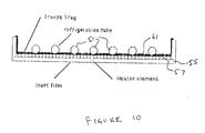
- FIG 10 there is shown a sectional view of a freeze plate 61 on which is deposited a heater structure that includes a layer of electrical conductor 57 and an adjacent insulating layer 55.
- This heater structure aids in optimizing the throughput of purified water in several ways.
- the typical internal structure of a freeze plate includes a plurality of tubes 5, for the circulating refrigerant that are fairly uniformly distributed at spaced intervals over the surface area of the freeze plate and that are formed in high thermal conductivity with the outer surface of the the freeze plate.
- Heat thus flows from water below the surface of the freeze plate 61 in substantially vertical direction through the layer of ice, and through the heater structure 55, 57 on the surface of the freeze plate, and (in some regions between tubes 51) along the freeze plate 61 to the tubes 51 with the circulating refrigerant therein.
- Heat flow along the freeze plate between tubes 51 may be slower or less efficient with higher thermal gradient per unit length than the heat flow through the ice layer and through the freeze plate 61 directly to a tube 51.
- the heater structure illustrated in Figure 10 includes the layer 55 of electrical insulation at least on the side of the electrical conductor 57 opposite the freeze plate 61.
- Such electrically insulating layer typically, Kapton or Teflon polymer materials available from DuPont Co.
- Kapton or Teflon polymer materials available from DuPont Co. is also a thermal insulator which therefore decreases the rate of heat flow directly to the tubes 51 to approximately the rate of heat flow along the freeze plate between the tubes 51.
- This structure therefore contributes to formation of an ice layer of more uniform thickness over the surface area of the freeze plate 61 without significantly altering the overall rate of heat flow from the water to the refrigerant circulating in the tubes 51.
- the electrical conductor 57 in the intermediate layer of the heater structure is connected via the controller 35 to conduct current to provide Joule heating during the ice-melting period of operation previously described.
- This heater structure may be retained in close, continuous thermal contact with the layer of ice during the melting period by resiliently biasing the freeze plate 61 assembly into the freeze tray 23, or vice-versa, in order to maintain surface contact between the heater structure and the ice layer in the freeze tray 23 as the ice layer melts.
- the electrical conductor 57 is connected via controller 35 to serve as one substantially equipotential electrode for establishing an electrostatic field in the impure water in freeze tray 23 during the ice formation period of operation, as previously described.
- the outer surface of the outer layer 55 (e.g. Teflon) of the heater structure exhibits smooth, substantially non-wetting surface characteristics which inhibits development or formation of nucleation sites as ice initially forms. These surface properties have been found to promote the formation of a more uniform layer of ice comprising substantially homogenous platelet-type crystals rather than spire-shaped crystals, with concomitant reductions of trapped impurities at dislocation sites in imperfect ice crystals.
- the vessel 63 is generally of cylindrical shape (i.e. right circular, or rectangular or elliptical, or the like) with thermally conductive side walls 65 forming an evaporator or freeze plate around substantially the entire perimeter, and with minimum interior dimension (e.g. diameter) selected to be larger than the thickness of the layer of ice formed adjacent the side walls. Remaining unfrozen impure water may therefore be drained from the center of the structure.
- An electrode 66 is substantially vertically oriented near the center of the structure for establishing an electrostatic field in the impure water during the ice formation period of operation to enhance the purity of the ice in the manner previously described.
- a heater structure 55, 57 similar to the one previously described in connection with freeze plate 23 may also be disposed on the interior walls of the cylindrical vessel, and the vessel may be closed at the upper end (except for air venting) in order to inhibit spills during operation in mobile environments such as in mobile homes or marine or military installations.
- FIG 12 there is shown a perspective sectional view of another embodiment of a freeze tray or vessel 68 in the structure of the present invention.
- the vessel 63 is generally of cylindrical shape, as previously described with reference to Figure 11, with a thermally-conductive freeze plate or tube 67 centrally disposed with the surrounding side walls 68.
- the evaporator or freeze tube 67 includes circulating refrigerant therein for forming the layer of ice with thickness less than the dimension to the adjacent the side walls 68 of the vessel.
- the inner dimension of the vessel e.g. diameter
- the freeze tube 67 may include a non-wetting surface, as previously described. Remaining unfrozen impure water may therefore be drained from the outer region of the central layer of ice, (i.e., near the inner walls of the vessel 68). Electrodes for establishing an electrostatic field in the impure water during the ice formation period of operation to enhance the purity of the ice in the manner previously described may be disposed on the walls of the vessel 68 and on the freeze tube 67 to wage impurities away from the freeze tube 67.
- Heating means for melting ice formed on the freeze tube 67 may include circulating heated refrigerant therethrough, or a current-conducting electrical heater, or infrared or microwave heaters, or the like, and the vessel may be closed at the upper end (except for air venting) in order to inhibit spills during operation in mobile environments such as in mobile homes or marine or military installations.
- freeze purification of impure water can be optimized for maximum throughput at minimum cost in accordance with the method and apparatus of the present invention by taking into account the size of freeze plate and the temperature of the refrigerant circulating therein, and by the magnitude of an applied electrical potential.
- the surface properties of the freeze plate are selected to promote the formation of more uniform ice crystals that inhibit entrapment of impurities at the ice-water interface.
- the surface structure of the freeze plate may be arranged and connected to exert electrostatic force on impurities during formation of the ice layer, as well as the supply Joule heating of the ice layer following removal of unfrozen, impure water.
Landscapes
- Life Sciences & Earth Sciences (AREA)
- Hydrology & Water Resources (AREA)
- Engineering & Computer Science (AREA)
- Environmental & Geological Engineering (AREA)
- Water Supply & Treatment (AREA)
- Chemical & Material Sciences (AREA)
- Organic Chemistry (AREA)
- Physical Water Treatments (AREA)
Applications Claiming Priority (2)
| Application Number | Priority Date | Filing Date | Title |
|---|---|---|---|
| US07/295,651 US4954151A (en) | 1989-01-10 | 1989-01-10 | Method and means for optimizing batch crystallization for purifying water |
| US295651 | 1989-01-10 |
Publications (2)
| Publication Number | Publication Date |
|---|---|
| EP0378166A2 true EP0378166A2 (de) | 1990-07-18 |
| EP0378166A3 EP0378166A3 (de) | 1991-01-16 |
Family
ID=23138636
Family Applications (1)
| Application Number | Title | Priority Date | Filing Date |
|---|---|---|---|
| EP19900100365 Withdrawn EP0378166A3 (de) | 1989-01-10 | 1990-01-09 | Verfahren und Vorrichtung zur Optimierung des stufenweisen Kristallisierens für die Wasserreinigung |
Country Status (2)
| Country | Link |
|---|---|
| US (1) | US4954151A (de) |
| EP (1) | EP0378166A3 (de) |
Cited By (1)
| Publication number | Priority date | Publication date | Assignee | Title |
|---|---|---|---|---|
| EP0811410A1 (de) * | 1996-06-05 | 1997-12-10 | Sulzer Chemtech AG | Verfahren und Vorrichtung zur Stofftrennung eines flüssigen Gemisches durch fraktionierte Kristallisation |
Families Citing this family (18)
| Publication number | Priority date | Publication date | Assignee | Title |
|---|---|---|---|---|
| US5231852A (en) * | 1991-01-18 | 1993-08-03 | Polar Spring Corporation | Melt system for liquid purification by batch crystallization |
| US5113664A (en) * | 1991-01-18 | 1992-05-19 | Polar Spring Corporation | Melt system for liquid purification by batch crystallization |
| US5162354A (en) * | 1991-12-20 | 1992-11-10 | Buckman Laboratories International, Inc. | 3-halo-5-halomethyl-2-oxazolidinones and their use as microbicides |
| US5438843A (en) * | 1994-01-18 | 1995-08-08 | Conlon; William M. | Means for liquid purification by batch crystallization |
| US5555747A (en) * | 1994-07-28 | 1996-09-17 | Polar Spring Corporation | Control of crystal growth in water purification by directional freeze crystallization |
| RU2186033C1 (ru) * | 2001-04-11 | 2002-07-27 | Уральский государственный технический университет | Способ улучшения качества питьевой воды замораживанием и оттаиванием |
| RU2186034C1 (ru) * | 2001-05-28 | 2002-07-27 | Уральский государственный технический университет | Способ обессоливания воды или растворов солей замораживанием и оттаиванием |
| US7504739B2 (en) * | 2001-10-05 | 2009-03-17 | Enis Ben M | Method of transporting and storing wind generated energy using a pipeline |
| AU2003211275A1 (en) * | 2002-02-27 | 2003-09-09 | Yoshihito Shirai | Process for producing concentrate by freezing and thawing and apparatus therefor |
| JP5017057B2 (ja) * | 2007-10-26 | 2012-09-05 | 株式会社日立製作所 | ヒートポンプシステム及びその運用方法並びに蒸気蒸発器システム |
| US20100115989A1 (en) * | 2008-11-13 | 2010-05-13 | Zenon Chrysostomou | Apparatus and method for producing potable water |
| NO334886B1 (no) * | 2009-01-26 | 2014-06-30 | Ncc Construction As | Anlegg og fremgangsmåte for nedsmelting og rensing av snø og is |
| US10099943B2 (en) | 2016-03-24 | 2018-10-16 | Jai H. Rho | Apparatus and methods for desalination and mineral reduction of water resources by vertical freezing |
| CN109916949B (zh) * | 2019-03-27 | 2021-07-20 | 天津城建大学 | 一种适用于饱和冻土的导热系数计算方法 |
| WO2021092108A1 (en) | 2019-11-06 | 2021-05-14 | Abstract Ice, Inc. | Systems and methods for creating clear ice |
| US11408659B2 (en) | 2020-11-20 | 2022-08-09 | Abstract Ice, Inc. | Devices for producing clear ice products and related methods |
| US12571573B2 (en) | 2022-11-21 | 2026-03-10 | Abstract Ice, Inc. | Devices for producing clear ice products |
| AU2024215251A1 (en) | 2023-02-02 | 2025-08-14 | Abstract Ice, Inc. | Devices for shaping clear ice products and related methods |
Family Cites Families (8)
| Publication number | Priority date | Publication date | Assignee | Title |
|---|---|---|---|---|
| FR1009865A (fr) * | 1948-07-03 | 1952-06-04 | Ateliers Et Chantiers Loire Sa | Procédé et dispositif pour la production d'eau douce à partir de solutions salines |
| FR1070515A (fr) * | 1952-10-21 | 1954-07-28 | Procédé de production d'eau potable et distillée | |
| US3354083A (en) * | 1964-02-20 | 1967-11-21 | Dept Of Chemical Engineering | Separation of fresh water from aqueous solutions |
| US3338065A (en) * | 1965-01-04 | 1967-08-29 | Carrier Corp | Water purifying apparatus and method |
| DE2224043A1 (de) * | 1965-09-13 | 1973-11-22 | Herbert Hohmann | Entsalzungsverfahren fuer salzloesungen, insbesondere fuer suesswasser-gewinnung aus seewasser |
| US3630042A (en) * | 1969-02-07 | 1971-12-28 | Ling Services | Method and system for desalinization of water |
| US3714791A (en) * | 1971-02-25 | 1973-02-06 | Pacific Lighting Service Co | Vapor freezing type desalination method and apparatus |
| US4799945A (en) * | 1987-10-27 | 1989-01-24 | Polar Spring Corporation | Dual freezing chamber system and method for water purification |
-
1989
- 1989-01-10 US US07/295,651 patent/US4954151A/en not_active Expired - Fee Related
-
1990
- 1990-01-09 EP EP19900100365 patent/EP0378166A3/de not_active Withdrawn
Cited By (2)
| Publication number | Priority date | Publication date | Assignee | Title |
|---|---|---|---|---|
| EP0811410A1 (de) * | 1996-06-05 | 1997-12-10 | Sulzer Chemtech AG | Verfahren und Vorrichtung zur Stofftrennung eines flüssigen Gemisches durch fraktionierte Kristallisation |
| US6024793A (en) * | 1996-06-05 | 2000-02-15 | Sulzer Chemtech Ag | Method and device for separating a substance from a liquid mixture by fractional crystallization |
Also Published As
| Publication number | Publication date |
|---|---|
| US4954151A (en) | 1990-09-04 |
| EP0378166A3 (de) | 1991-01-16 |
Similar Documents
| Publication | Publication Date | Title |
|---|---|---|
| US4954151A (en) | Method and means for optimizing batch crystallization for purifying water | |
| KR910003056B1 (ko) | 2중 동결 격실 정수 시스템 및 방법 | |
| US6935124B2 (en) | Clear ice making apparatus, clear ice making method and refrigerator | |
| JPH05126446A (ja) | 澄んだ氷片の製造用装置と、その制御回路 | |
| RU2274607C2 (ru) | Способ очистки воды и установка для его осуществления | |
| US6119464A (en) | Beverage servers and their controlling methods | |
| EA025716B1 (ru) | Способ очистки воды методом перекристаллизации и теплообменная емкость (варианты) для его осуществления | |
| US4601040A (en) | Condensers | |
| WATER | Chang et al.[45] Date of Patent: Sep. 4, 1990 | |
| KR20010112184A (ko) | 냉매회로를 이용한 물의 냉수 온수 및 고온수 공급장치 | |
| WO2015030631A1 (ru) | Способ получения и хранения талой воды | |
| RU2732603C1 (ru) | Устройство для получения энергии фазового перехода вода-лед | |
| SU1196627A1 (ru) | Каскадный охладитель | |
| EA023930B1 (ru) | Аппарат для очистки воды методом перекристаллизации | |
| RU191503U1 (ru) | Теплообменное устройство для системы очистки воды методом перекристаллизации | |
| EA024704B1 (ru) | Способ очистки воды и аппарат для его осуществления | |
| RU29299U1 (ru) | Установка для опреснения воды | |
| US12103865B1 (en) | Freezing desalination system using thermoelectric coolers | |
| RU2786296C1 (ru) | Теплообменное устройство для системы очистки воды методом перекристаллизации | |
| KR890005521Y1 (ko) | 식수용 보리차 제조기 | |
| KR101063983B1 (ko) | 급속냉각형 음수기 | |
| JP2535603B2 (ja) | 蓄熱装置 | |
| WO2023200358A1 (ru) | Теплообменное устройство для системы очистки воды методом перекристаллизации | |
| JPH08219501A (ja) | 氷蓄熱装置 | |
| JP2000042555A (ja) | 電解水冷却装置 |
Legal Events
| Date | Code | Title | Description |
|---|---|---|---|
| PUAI | Public reference made under article 153(3) epc to a published international application that has entered the european phase |
Free format text: ORIGINAL CODE: 0009012 |
|
| AK | Designated contracting states |
Kind code of ref document: A2 Designated state(s): AT BE CH DE DK ES FR GB GR IT LI LU NL SE |
|
| PUAL | Search report despatched |
Free format text: ORIGINAL CODE: 0009013 |
|
| AK | Designated contracting states |
Kind code of ref document: A3 Designated state(s): AT BE CH DE DK ES FR GB GR IT LI LU NL |
|
| 17P | Request for examination filed |
Effective date: 19901228 |
|
| 17Q | First examination report despatched |
Effective date: 19920520 |
|
| STAA | Information on the status of an ep patent application or granted ep patent |
Free format text: STATUS: THE APPLICATION IS DEEMED TO BE WITHDRAWN |
|
| 18D | Application deemed to be withdrawn |
Effective date: 19921201 |