EP0377250B1 - Ventilstellglied mit verbesserter Leistung - Google Patents
Ventilstellglied mit verbesserter Leistung Download PDFInfo
- Publication number
- EP0377250B1 EP0377250B1 EP89203288A EP89203288A EP0377250B1 EP 0377250 B1 EP0377250 B1 EP 0377250B1 EP 89203288 A EP89203288 A EP 89203288A EP 89203288 A EP89203288 A EP 89203288A EP 0377250 B1 EP0377250 B1 EP 0377250B1
- Authority
- EP
- European Patent Office
- Prior art keywords
- valve
- control valve
- piston
- air
- permanent magnet
- Prior art date
- Legal status (The legal status is an assumption and is not a legal conclusion. Google has not performed a legal analysis and makes no representation as to the accuracy of the status listed.)
- Expired - Lifetime
Links
- 239000012530 fluid Substances 0.000 claims description 27
- 238000013016 damping Methods 0.000 claims description 8
- 230000000694 effects Effects 0.000 claims description 6
- 238000004891 communication Methods 0.000 claims description 5
- 230000003472 neutralizing effect Effects 0.000 claims description 4
- 238000006386 neutralization reaction Methods 0.000 claims description 2
- 230000007246 mechanism Effects 0.000 description 5
- XEEYBQQBJWHFJM-UHFFFAOYSA-N Iron Chemical compound [Fe] XEEYBQQBJWHFJM-UHFFFAOYSA-N 0.000 description 4
- 238000002485 combustion reaction Methods 0.000 description 4
- 238000013022 venting Methods 0.000 description 4
- 238000010276 construction Methods 0.000 description 3
- 230000006835 compression Effects 0.000 description 2
- 238000007906 compression Methods 0.000 description 2
- 230000003111 delayed effect Effects 0.000 description 2
- 239000007789 gas Substances 0.000 description 2
- 229910052742 iron Inorganic materials 0.000 description 2
- 238000004519 manufacturing process Methods 0.000 description 2
- 230000001360 synchronised effect Effects 0.000 description 2
- 230000007704 transition Effects 0.000 description 2
- 235000014676 Phragmites communis Nutrition 0.000 description 1
- 230000002159 abnormal effect Effects 0.000 description 1
- 230000009471 action Effects 0.000 description 1
- 238000013459 approach Methods 0.000 description 1
- 230000007423 decrease Effects 0.000 description 1
- 238000006073 displacement reaction Methods 0.000 description 1
- 238000004146 energy storage Methods 0.000 description 1
- 230000006872 improvement Effects 0.000 description 1
- 238000011084 recovery Methods 0.000 description 1
- 230000009467 reduction Effects 0.000 description 1
- 230000004044 response Effects 0.000 description 1
Images



Classifications
-
- F—MECHANICAL ENGINEERING; LIGHTING; HEATING; WEAPONS; BLASTING
- F01—MACHINES OR ENGINES IN GENERAL; ENGINE PLANTS IN GENERAL; STEAM ENGINES
- F01L—CYCLICALLY OPERATING VALVES FOR MACHINES OR ENGINES
- F01L9/00—Valve-gear or valve arrangements actuated non-mechanically
- F01L9/10—Valve-gear or valve arrangements actuated non-mechanically by fluid means, e.g. hydraulic
- F01L9/16—Pneumatic means
-
- F—MECHANICAL ENGINEERING; LIGHTING; HEATING; WEAPONS; BLASTING
- F01—MACHINES OR ENGINES IN GENERAL; ENGINE PLANTS IN GENERAL; STEAM ENGINES
- F01L—CYCLICALLY OPERATING VALVES FOR MACHINES OR ENGINES
- F01L9/00—Valve-gear or valve arrangements actuated non-mechanically
- F01L9/20—Valve-gear or valve arrangements actuated non-mechanically by electric means
-
- Y—GENERAL TAGGING OF NEW TECHNOLOGICAL DEVELOPMENTS; GENERAL TAGGING OF CROSS-SECTIONAL TECHNOLOGIES SPANNING OVER SEVERAL SECTIONS OF THE IPC; TECHNICAL SUBJECTS COVERED BY FORMER USPC CROSS-REFERENCE ART COLLECTIONS [XRACs] AND DIGESTS
- Y10—TECHNICAL SUBJECTS COVERED BY FORMER USPC
- Y10T—TECHNICAL SUBJECTS COVERED BY FORMER US CLASSIFICATION
- Y10T137/00—Fluid handling
- Y10T137/8593—Systems
- Y10T137/86493—Multi-way valve unit
- Y10T137/86574—Supply and exhaust
- Y10T137/86582—Pilot-actuated
- Y10T137/86614—Electric
Definitions
- the present invention is dealing with a bistable electronically controlled fluid powered transducer having a first member reciprocative in a housing along an axis between first and second positions; a control valve reciprocative in said housing along said axis between open and closed positions and having first and second opposite surfaces; latching means for closing and holding said control valve in its closed position; electromagnetic means for temporarily neutralizing the effect of said latching means to release the control valve to move from the closed position towards the open position; fluid pressure means comprising a fluid pressure source for providing fluid pressure to said valve means to energize said electromagnetic means to provide a electric pulse to temporarily neutralize the effect of said latching means; each of said member and said valve having first and second opposite axial ends.
- the invention relates generally to a two position, straight line motion actuator and more particularly to a fast acting actuator which utilizes pneumatic energy against a piston to perform extremely fast transit times between the two positions.
- the invention utilizes a pair of control valves to gate high pressure air to the piston and latching magnets to hold the valves in their closed positions until a timed short term electrical energy pulse excites a coil around a magnet to partially neutralize the magnet's holding force and release the associated valve to move in response to high pressure air to a open position. Pressurised pneumatic gases accelerate the piston rapidly from one position to the other position.
- This actuator finds particular utility in opening and closing the gas exchange, i.e., intake or exhaust, valves of an otherwise conventional internal combustion engine. Due to its fast acting trait, the valves may be moved between full open and full closed positions almost immediately rather than gradually as is characteristic of cam actuated valves.
- the actuator mechanism may find numerous other applications such as in compressor valving and valving in other hydraulic or pneumatic devices, or as a fast acting control valve for fluidic actuators or mechanical actuators where fast controlled action is required such as moving items in a production line environment.
- EP-A-0 281 192 there is disclosed a valve actuator which has permanent magnet latching at the open and closed positions. Electromagnetic repulsion may be employed to cause the valve to move from one position to the other. Several damping and energy recovery schemes are also included.
- EP-A-0 328 194 where energy is stored from one valve motion to power the next
- EP-A-0 328 192 wherein a spring (or pneumatic equivalent) functions both as a damping device and as an energy storage device ready to supply part of the accelerating force to aid the next transition from one position to the other.
- a spring or pneumatic equivalent
- One distinguishing feature of application EP-A-0 328 192 is the fact that initial accelerating force is partly due to electromagnetic repulsion somewhat like that employed in the first above mentioned copending application.
- the reciprocating piston of a pneumatically driven valve actuator has several air passing bores extending in its direction of reciprocation for providing an effective and efficient source of low or atmospheric air pressure at the opposite ends of the piston.
- the piston also has a undercut which, at the appropriate time, passes high pressure air to the back side of the air control valve thereby aiding in closing the control valve. The result is a higher air pressure closing the control valve than the air pressure used to open the control valve.
- an actuator has one-way pressure relief valves similar to the relief valves in Applicant's application EP-A-0 347 978 to vent captured air back to the high pressure source.
- the actuator also has "windows" or venting valve undercuts in the main piston shaft which are of reduced size as compared to the windows in other of the cases filed on even date herewith resulting in a higher compression ratio.
- the actuator of this application increases the area which is pressurized when the air control valve closes thereby still further reducing the magnetic force required.
- valve actuator cover provides a simplified air return path for low pressure air and a variety of new air venting paths allow use of much larger high pressure air accumulators close to the working piston.
- windows which are cupped out or recessed regions on the order of 0.1 inches in depth along a somewhat enlarged portion of the shaft of the main piston, for passing air from one region or chamber to another or to a low pressure air outlet.
- These cases may also employ a slot centrally located within the piston cylinder for supplying a intermediate latching air pressure as in the above noted application EP-A-0 328 193 and a reed valve arrangement for returning air compressed during piston damping to the high pressure air source as in the above noted application EP-A-0 347 978.
- a bistable electronically controlled fluid powered transducer is known from US-A-3,844,528.
- the power or working piston which moves the engine valve between open and closed positions is separated from the latching components and certain control valving structures so that the mass to be moved is materially reduced allowing much faster operation as explained in the above mentioned application EP-A-0 328 193.
- a bistable fluid powered actuating device characterized by extremely fast transition times and economy of size, manufacture and power requirements; the provision of a pneumatically powered valve actuator where the control valves within the actuator cooperate with, but operate separately from the main working piston and are urged to a latched or closed position through kinetic energy transfer from piston dampening; and the provision in combination therewith of balanced pneumatic pressure on opposite sides of the control valve during latching or closing whereby the latching magnets are reduced in size and cost and required power to operate the valve.
- the bistable electronically controlled fluid powered transducer is characterized in that said latching means are magnetic latching means comprising a permanent magnet, said fluid pressure means urging said control valve toward said open valve position against the holding force of said permanent magnet, said control valve being adapted to move toward said open position under fluid pressure from said source upon neutralization of the holding force of the permanent magnet by said electromagnetic means, said member first axial end carrying a valve end engaging abutment for abutting said valve first axial end to urge said valve towards said closed position during travel of said member towards said first position thereby damping the motion of said first member and providing impetus to said valve towards said closed position.
- the bistable electronically controlled fluid powered transducer has an air powered piston which is reciprocable along an axis between first and second positions along with a control valve reciprocable along the same axis between open and closed positions.
- a magnetic latching arrangement functions to hold or latch the control valve in the closed position while an electromagnetic arrangement may be energized to temporarily weaken the effect of the permanent magnet latching arrangement to release the control valve to move from the closed position to the open position under pneumatic force.
- Energization of the electromagnetic arrangement causes movement of the control valve in one direction along the axis allowing fluid from a high pressure source to drive the piston in the opposite direction from the first position to the second position along the axis.
- the distance between the first and second positions of the piston is typically greater than the distance between the open and closed positions of the valve.
- the electromagnetic arrangement comprises a coil formed about a latching permanent magnet and is pulsed to temporarily weaken the permanent magnet thus unlatching its respective air control valve.
- the control valve has one surface subject to a fluid pressure to move the valve toward its open position. Movement of the control valve after unlatching introduces fluid pressure to a primary working source of the piston to move the piston toward its second position. Movement of the piston, in turn, introduces fluid pressure to a control valve surface opposite to the one surface to effectively balance fluid pressure across the control valve and significantly reduce the force required by the permanent magnet to reclosed the control valve.
- Another feature of this invention is the provision of a pair of annular chambers that communicate with a low pressure source when their respective air valves are in a closed position but which become sealed from the source as the valves move to their respective open positions.
- the air in the scaled chambers is compressed as the air valves move to their open positions and thus acts as an air return spring to close the valves, again reducing the size and required strengths of the permanent latching magnet
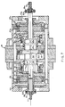
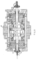
- the valve actuator is illustrated sequentially in Figures 1-8 to illustrate various component locations and functions in moving a poppet valve or other component (not shown) from a closed to an open position. Motion in the opposite direction although not described will be clearly understood from the symmetry of the components. Symmetrical components on the right side of the Figures are assigned the same reference numeral as corresponding components on the left side, with the exception that the reference numerals have the suffix "a.”
- the actuator includes a shaft or stem 11 which may form a part of or connect to an internal combustion engine poppet valve.
- the actuator also includes a low mass reciprocable piston 13 carrying an o-ring, and a pair of reciprocating or sliding control-valve members 15 and 15a enclosed within a housing 19.
- the control valve members 15 and 15a are latched in one position by permanent magnets 21 and 21a respectively and may be dislodged from their respective latched positions by pulse energization of coils 25 and 25a from a pulse source not shown but synchronized with piston movement.
- Valves 15, 15a each comprise annular bodies having elongated tubular shafts, 17, 17a respectively.
- the permanent magnet latching arrangement also includes iron pole pieces or armatures 20 and 20a.
- the control valve members or shuttle valves 15 and 15a cooperate with both the piston 13 and the housing 19 to achieve the various porting functions during operation.
- the housing 19 has a high pressure annular cavity 39 fed by pump, not shown, and a low pressure cavity 41 which is relieved to atmosphere.
- the low pressure may be about atmospheric pressure while the high pressure is on the order of 100 psi gauge pressure or pressure above atmospheric pressure.
- Figure 1 shows an initial state with piston 13 in the extreme leftward position and with the air control valve 15 latched closed.
- the annular ring 29 of valve 15 is seated in an annular slot in the housing 19 and seals against an o-ring 31. This seals the pressure in cavity 39 and prevents the application of any moving force to the main piston 13.
- the main piston 13 is being urged to the left (latched) by the pressure in cavity or chamber 35 which is greater than the pressure in annular chamber or cavity 41 which, in Fig. 1., communicates with surface 14 of recessed body 32 through annular passage 16.
- annular opening 16 is in its final open position after having released compressed air from annular cavity 37 at the end of a previous leftward piston stroke.
- Cavities 37, 37a are fluted to provide bearing surfaces for the recessed bodies 32, 32a attached to and integral with piston 13.
- the shuttle valve 15 has moved toward the left, for example, 0.060 in. while piston 13 has not yet moved and air at a high pressure now enters shallow recesses or "windows" 34, of which there are four equally spaced about body 32, from cavity 39 applying a motive force to the left face 42 of piston 13.
- the air valve 15 has opened because of an electrical pulse applied to coil 25 which has temporarily neutralized or weakened the holding force on iron armature or plate 20 by permanent magnet 21. Armature 20 is fixed to the end of valve 15. When that holding force is temporarily neutralized, air pressure in cavity 39 which is applied to the air pressure responsive annular face 49 of valve 15 causes the valve to open.
- FIG 3 shows the leftward movement or opening of the air valve 15 to about 0.110 in. (approximately wide open) and movement of the piston 13 about 0.140 in. to the right.
- the high pressure air supply was beginning to the cavity 37 and to the face 42 of piston 13 driving that piston toward the right. That high pressure air supply to cavity 44 is now cut off by the edge of recess 34 passing the annular shoulder 55 of the housing 19.
- Piston 13 continues rightwardly, however, due to the existing high pressure air in cavity 44.
- the relative movement between valve 15 and piston 13 has almost reached the point where annular shoulder 45 on valve 15 will open a fluid path between cavity 39 and chamber 37 through recesses 26 causing a high pressure on annular surface 18 of valve 15 and connected surfaces to substantially balance the axial pressures on valve 15.
- the piston 13 has moved approximately .240 inches and is continuing to move toward the right in Figure 4 and the air valve 15 is still at .110 inches and has reached its maximum leftward open displacement. Shoulder 45 has fully cleared the associated edge of recess 26 to introduce pressure from cavity 39 to chamber 37 around annular land 27. The valve 15 will tend to remain in this position for a short time due to the continuing air pressure on the annular surface 49, and connected surfaces, from high pressure source 39. Equalization of the pressure across the air valve reduces the force required to return the air valve from its leftmost motion. Thus the magnetic attraction of the armature 20 by the permanent magnet 21 pulls the air valve 15 back toward its closed position. By venting the high pressure from source 39 through recesses 26, which are positioned aft of recesses 34, equalization of pressure on surfaces 18 and 49 is delayed until piston 13 is well advanced and there is no likelihood that valve 15 will prematurely close.
- the air valve 15 is about .080 inches from its closed position and is beginning to return to its closed position since all pressure around the valve has been neutralized and only the attractive force of magnet 21 on disk 20 is causing the disk to move back toward the magnetic latch. Piston 13 has moved about .340 inches in Fig. 5.
- An intermediate pressure such as 4 psi gauge, is introduced from intermediate ports 47 (Fig. 6) supplied by a source, not shown, into cavity 44 so that the high pressure air in chamber 44 has blown down to the intermediate pressure.
- This feature has also been disclosed in the above referenced application Serial No. 153,155 which is incorporated herein by reference.
- Vents 47 dump expanded air from primary working surface 42 and remove the accelerating force from the piston.
- the vents 47 also function to introduce air at the intermediate pressure to be captured and compressed by the opposite primary working surface 42a of the piston to slow piston motion as it nears its second position and vents 47 supply intermediate pressure air to working surface 42 of the piston to temporarily hold the piston in its second position pending the next opening of air control valve 15a.
- Figure 6 illustrates air valves 15, 15a in their fully closed positions and piston 13 approaching its extreme rightward position, the highly pressurized air in chamber 35a being exhausted to atmosphere through recess 34a, cavity 50a and cavity 41a. Due to the aforementioned symmetry of valve construction, the movements of valve 15a and piston 13 is the mirror of the previously described operation of valve 15 and piston 13.
- valve 15 is approximately in the position of Fig. 5 (fully open), the pressure in chamber 35 is increasing, and piston 13 has traveled .400 inches. The high pressure air from cavity 39 has been cut off from surface 18 and chamber 37 has expanded causing a pressure differential across valve 15 urging it to the open position. Due to frictional resistance and/or magnet 21 is of such reduced size and strength it is not strong enough to pull the armature closed against this pressure differential, valve 15 has not moved in a closing direction while piston 13 has continued in its movement.
- Abutments 51, 51a are adjustably positioned on piston shaft 11 and carry o-rings 52, 52a on their respective inner surfaces that are in abutting relation to annular feet 53, 53a of armatures 20, 20a respectively when valves 15, 15a are fully open. Since piston 13 is moving rightwardly, abutment 51 will urge armature 20 rightwardly toward its closed position. As armature 20 approaches magnet 21, the magnet attraction increases geometrically so that even a reduced size and strength magnet 21 will provide adequate closing force of valve 15. Thus it is seen that abutment 51 aids in the closing of valve 15 but does not participate in the final closing movement. This reduces the wear and stress on the components. It should be remembered that reducing the size of magnets 21, 21a also reduces the required size of coils 25, 25a and their power requirements.
- Figure 8 illustrates valve 15 in an open position slightly closed from the Fig. 6 position, about .080 inches from the closed position, and a piston 13 travel of about .430 inches.
- Valve 15 continues under the influence of abutment 51 on foot 53 in its closing motion and since the magnetic force between magnet 21 and armature 20 is increasing geometrically as the separating distance decreases, valve 15 will close to the position shown in Fig. 6 under the magnetic attraction of magnet 21 only. It should be understood that it may be necessary to close valve 15 with the aid of abutment 51 during only a fraction of the operation duty cycle of the valves and then due to some abnormal interferences to valve operation.
- Figure 9 illustrates a second embodiment of this invention that is similar in all respects of construction and operation to that illustrated in Figs. 1-8 except that magnets 21, 21a are larger and stronger so that it is less likely for abutments 51, 51a to become necessary to aid in closing valves 15, 15a, respectively. Magnets 21, 21a and coils 25, 25a while larger and stronger than those in the embodiment of Figs. 1-8, are still smaller than might be otherwise necessary due to the aforementioned balancing of air pressures across valve 15.
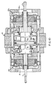
- Figure 10 illustrates a further embodiment of this invention similar in operation and construction with similar components carrying similar reference numerals to the embodiment of Fig. 9 with the following differences.
- the primary difference is that air or control valve 57 in Fig. 10 instead of having balanced pneumatic pressures and/or an abutment on the piston shaft to aid in its closing (left to right) movement, a closed annular cavity is created on the opening movement of air valve in which the pneumatic pressure increases as the valve continues in its opening movement, thus providing an "air spring" to aid in the closing valve movement so that once again the size, strength and cost of magnet 21 is reduced with a corresponding reduction in coil 25 and the power required thereby.
- Piston shaft 11 is integral with and carries recessed bodies 59, 59a each of which have four circumferentially equally spaced shallow recesses or windows 61, 61a respectively. It is noted there are no recesses corresponding to recesses 26, 26a in the earlier described embodiments since there is no balancing of pneumatic pressure on either side of annular valves 57, 57a to aid in the closing (movement towards piston 13) valve movement. Also it is noted that there are no abutments 51, 51a on shaft ends 11, 11a respectively.
- Opening motion of air valve 57 closes annular vent passage 63 between annular cavity 65 and low pressure atmospheric annular cavity 41. Further opening movement of valve 57 will compress the air in cavity 65 and at the open valve 15 position (not shown) the compressed air in cavity 65 will act as an air spring to assist magnet 21 in the closing valve movement.
- the size and strength of magnet 21 and the compression in cavity 65 may be selected as desired.
- abutments similar to abutments 51, 51a may be added if desired to shaft ends 11, 11a respectively to aid in closing valves 57, 57a respectively to further reduce the size and strengths of magnets 21, 21a and associated coils 25, 25a and the power supplied thereto.
Landscapes
- Engineering & Computer Science (AREA)
- Mechanical Engineering (AREA)
- General Engineering & Computer Science (AREA)
- Magnetically Actuated Valves (AREA)
- Actuator (AREA)
Claims (7)
- Bistabiler, elektronisch gesteuerter, flüssigkeitsbetriebener Wandler mit einem ersten Element (13), das längs einer Achse in einem Gehäuse (19) zwischen ersten und zweiten Stellungen hin- und herlaufen kann, mit einem Regelventil (15, 17) zum Hin- und Herlaufen im Gehäuse (19) längs der Achse zwischen geöffneten und geschlossenen Stellungen und mit ersten und zweiten einander gegenüberliegenden Flächen (18, 49), mit einem Sperrmittel (20, 21) zum Schließen und Festhalten des Regelventils (15, 57) in einer geschlossenen Stellung, mit einem elektromagnetischen Mittel (25) zum vorübergehenden Neutralisieren des Effekts des Sperrmittels (21) zum Freigeben des Regelventils (15) zum Verschieben von der geschlossenen in die geöffnete Stellung, und mit einem Flüssigkeitsdruckregelmittel mit einer Flüssigkeitsdruckquelle (39) zum Ausüben von Flüssigkeitsdruck auf das Ventil (15, 57), wobei das Druckregelmittel zum Erregen des elektromagnetischen Mittels (25) zum Erzeugen eines elektrischen Impulses zum vorübergehenden Neutralisieren des Effekts des Sperrmittels (20, 21) dient, und jedes der Elemente (13) und das Ventil (15, 57) erste und zweite einander gegenüberliegende Axialenden (51, 53) aufweist,
dadurch gekennzeichnet, daß das Sperrmittel (20, 21) ein magnetisches Sperrmittel mit einem Dauermagneten (21) ist, daß das Flüssigkeitsdruckmittel (39) das Regelventil (15, 57) gegen die Haltekraft des Dauermagneten (21) nach der offenen Ventilstellung verschiebt, daß beim Neutralisieren der Haltekraft des Dauermagneten (21) durch das elektromagnetische Mittel das Regelventil (15, 57) zum Verschieben nach seiner offenen Stellung unter Flüssigkeitsdruck aus der Quelle (39) angepaßt wird, daß das erste Axialende des Elements, wobei das Ende ein Ventilende trägt, mit dem Auflager (51) zum Aufliegen des ersten Axialendes (53) des Ventils zusammenarbeitet, um das Ventil (15, 57) bei der Bewegung des Elements (13) nach seiner ersten Stellung in die geschlossene Ventilstellung zu bringen, wobei die Bewegung des ersten Elements (15) gedämpft und auf das Ventil (15, 57) eine Stoßkraft nach seiner geschlossenen Stellung ausgeübt wird. - Apparat nach Anspruch 1 mit einem ersten Durchlaßmittel (55) im Gehäuse (19) in Zusammenarbeit mit dem ersten Element (13) und dem Ventil (15) zum Herstellen einer Flüssigkeitsverbindung zwischen der Quelle (39) und einer Seite des ersten Elements (13) zum axialen Bewegen des ersten Elements (13), wenn das Ventil (15) sich zwischen den geschlossenen und geöffneten Stellungen verschiebt, mit einem zweiten Durchlaßmittel (45) im Gehäuse in Zusammenarbeit mit dem ersten Element (13) und dem Ventil (15) zum Herstellen einer Flüssigkeitsverbindung zwischen der Quelle (39) und den ersten und zweiten Flächen (49, 18) des Ventils (15) im wesentlichen zum Ausgleichen des axialen Flüssigkeitsdrucks auf das Ventil (15), wenn das Ventil (15) in der offenen Stellung steht, wobei sich das Ventil (15) unter der Einwirkung des Dauermagneten (21) zu schließen anfangen kann.
- Apparat nach Anspruch 1 mit einem Mittel zum erneuten Schließen des Regelventils (57), mit einem Niederdruckaulaß (41) und einer Kammer (65) zum Verbinden mit dem Niederdruckauslaß (41), wenn das Regelventil (57) in der geschlossenen Stellung steht, wobei das Regelventil (57) bei seiner Bewegung in seine geöffnete Stellung wirksam ist, um die Kammer (65) vom Niederdruckauslaß (41) abzudichten, wobei sich eine abgeschlossene Luftkammer für zu komprimierende Luft bei Weiterbewegung des Regelventils (57) nach seiner offenen Stellung bildet, und die Kammer (65) als Rückkehr-Luftfeder für das Regelventil (57) dient.
- Apparat nach Anspruch 1, 2 oder 3, worin das Ventil (15, 57) und das Element (13) koaxial sind, das Ventil (15, 57) eine axiale Bohrung (17) aufweist, das Element (13) sich durch die Bohrung (17) erstreckt und das Auflager (51) diametral größer ist als die Bohrung (17).
- Apparat nach Anspruch 1, 2, 3 oder 4, worin das Ventil (15, 57) einen Anker (20) trägt, und der Dauermagnet (21) des Sperrmittels im Gehäuse (19) für Zusammenarbeit mit dem Anker (20) angeordnet ist, um den Anker (20) und das Ventil (15, 57) in einer geschlossenen Stellung festzuhalten.
- Apparat nach einem der Ansprüche 1 bis 5, worin das elektromagnetische Mittel eine Spule (25) enthält, die um den Dauermagneten (21) gewickelt ist.
- Apparat nach Anspruch 4, 5 oder 6, worin das Auflager eine federnde, mit dem Ventil zusammenarbeitende Fläche (53) trägt.
Applications Claiming Priority (2)
| Application Number | Priority Date | Filing Date | Title |
|---|---|---|---|
| US07/294,728 US4875441A (en) | 1989-01-06 | 1989-01-06 | Enhanced efficiency valve actuator |
| US294728 | 2002-11-15 |
Publications (2)
| Publication Number | Publication Date |
|---|---|
| EP0377250A1 EP0377250A1 (de) | 1990-07-11 |
| EP0377250B1 true EP0377250B1 (de) | 1993-12-08 |
Family
ID=23134682
Family Applications (1)
| Application Number | Title | Priority Date | Filing Date |
|---|---|---|---|
| EP89203288A Expired - Lifetime EP0377250B1 (de) | 1989-01-06 | 1989-12-21 | Ventilstellglied mit verbesserter Leistung |
Country Status (5)
| Country | Link |
|---|---|
| US (1) | US4875441A (de) |
| EP (1) | EP0377250B1 (de) |
| JP (1) | JPH02245503A (de) |
| CA (1) | CA2007087A1 (de) |
| DE (1) | DE68911285T2 (de) |
Families Citing this family (11)
| Publication number | Priority date | Publication date | Assignee | Title |
|---|---|---|---|---|
| US4942852A (en) * | 1989-01-06 | 1990-07-24 | Magnavox Government And Industrial Electronics Company | Electro-pneumatic actuator |
| US4872425A (en) * | 1989-01-06 | 1989-10-10 | Magnavox Government And Industrial Electronics Company | Air powered valve actuator |
| US4967702A (en) * | 1989-01-06 | 1990-11-06 | Magnavox Government And Industrial Electronics Company | Fast acting valve |
| US4991548A (en) * | 1989-01-06 | 1991-02-12 | Magnavox Government And Industrial Electronics Company | Compact valve actuator |
| US4875441A (en) * | 1989-01-06 | 1989-10-24 | Magnavox Government And Industrial Electronics Company | Enhanced efficiency valve actuator |
| US5131354A (en) * | 1989-11-09 | 1992-07-21 | North American Philips Corporation | Method of operating a two-stroke-cycle engine with variable valve timing in a four-stroke-cycle mode |
| US4974495A (en) * | 1989-12-26 | 1990-12-04 | Magnavox Government And Industrial Electronics Company | Electro-hydraulic valve actuator |
| US5003938A (en) * | 1989-12-26 | 1991-04-02 | Magnavox Government And Industrial Electronics Company | Pneumatically powered valve actuator |
| US5255641A (en) | 1991-06-24 | 1993-10-26 | Ford Motor Company | Variable engine valve control system |
| DE19725218C2 (de) * | 1997-06-15 | 2000-11-02 | Daimler Chrysler Ag | Vorrichtung zur Betätigung eines Gaswechselventiles für eine Brennkraftmaschine |
| GB0322444D0 (en) * | 2003-09-25 | 2003-10-29 | Rts Thurnall Plc | Actuator assembly |
Family Cites Families (11)
| Publication number | Priority date | Publication date | Assignee | Title |
|---|---|---|---|---|
| DE421002C (de) * | 1925-11-04 | D Aviat Louis Breguet Sa Des A | Steuerung von Ventilen, insbesondere fuer Explosionsmotoren, durch Fluessigkeiten oder Gase | |
| US2552960A (en) * | 1946-09-27 | 1951-05-15 | Nordberg Manufacturing Co | Gas actuated inlet valve |
| CH503892A (de) * | 1969-08-30 | 1971-02-28 | Bosch Gmbh Robert | Steuerung von Ein- und Auslassventilen von Brennkraftmaschinen durch Flüssigkeit |
| US3844528A (en) * | 1971-12-30 | 1974-10-29 | P Massie | Electrically operated hydraulic valve particularly adapted for pollution-free electronically controlled internal combustion engine |
| US3738337A (en) * | 1971-12-30 | 1973-06-12 | P Massie | Electrically operated hydraulic valve particularly adapted for pollution-free electronically controlled internal combustion engine |
| CH592835A5 (de) * | 1975-04-29 | 1977-11-15 | Lucifer Sa | |
| FR2379969A7 (fr) * | 1977-02-07 | 1978-09-01 | Semt | Procede et dispositif de freinage pneumatique d'un moteur a combustion interne reversible par exemple |
| CH620748A5 (de) * | 1978-04-04 | 1980-12-15 | Lucifer Sa | |
| FR2557558B1 (fr) * | 1984-01-02 | 1986-05-23 | Degremont Sa | Filtre immerge a remplissage de materiau granulaire |
| US4852528A (en) * | 1988-06-20 | 1989-08-01 | Magnavox Government And Industrial Electronics Company | Pneumatic actuator with permanent magnet control valve latching |
| US4875441A (en) * | 1989-01-06 | 1989-10-24 | Magnavox Government And Industrial Electronics Company | Enhanced efficiency valve actuator |
-
1989
- 1989-01-06 US US07/294,728 patent/US4875441A/en not_active Expired - Lifetime
- 1989-12-21 EP EP89203288A patent/EP0377250B1/de not_active Expired - Lifetime
- 1989-12-21 DE DE68911285T patent/DE68911285T2/de not_active Expired - Fee Related
-
1990
- 1990-01-03 CA CA002007087A patent/CA2007087A1/en not_active Abandoned
- 1990-01-06 JP JP2000239A patent/JPH02245503A/ja active Pending
Also Published As
| Publication number | Publication date |
|---|---|
| US4875441A (en) | 1989-10-24 |
| JPH02245503A (ja) | 1990-10-01 |
| CA2007087A1 (en) | 1990-07-06 |
| EP0377250A1 (de) | 1990-07-11 |
| DE68911285D1 (de) | 1994-01-20 |
| DE68911285T2 (de) | 1994-05-26 |
Similar Documents
| Publication | Publication Date | Title |
|---|---|---|
| US4831973A (en) | Repulsion actuated potential energy driven valve mechanism | |
| US4852528A (en) | Pneumatic actuator with permanent magnet control valve latching | |
| EP0328194B1 (de) | Ventilvorrichtung mit potentiellem magnetischen Antrieb | |
| JPH07269318A (ja) | 対称式双安定性空気圧式アクチュエータ機構 | |
| JPH04132810A (ja) | 電気制御液圧作動弁アクチュエータ | |
| EP0377250B1 (de) | Ventilstellglied mit verbesserter Leistung | |
| CA2040697A1 (en) | Low energy hydraulic actuator | |
| EP0377244B1 (de) | Schnell arbeitendes Ventil | |
| EP0377254B1 (de) | Pneumatisches Stellglied | |
| US4873948A (en) | Pneumatic actuator with solenoid operated control valves | |
| US4942852A (en) | Electro-pneumatic actuator | |
| US4899700A (en) | Pneumatically powered valve actuator | |
| US4991548A (en) | Compact valve actuator | |
| EP0377246B1 (de) | Pneumatisches Ventilstellglied |
Legal Events
| Date | Code | Title | Description |
|---|---|---|---|
| PUAI | Public reference made under article 153(3) epc to a published international application that has entered the european phase |
Free format text: ORIGINAL CODE: 0009012 |
|
| AK | Designated contracting states |
Kind code of ref document: A1 Designated state(s): DE ES FR GB IT SE |
|
| 17P | Request for examination filed |
Effective date: 19901219 |
|
| 17Q | First examination report despatched |
Effective date: 19920317 |
|
| RAP1 | Party data changed (applicant data changed or rights of an application transferred) |
Owner name: MAGNAVOX ELECTRONIC SYSTEMS COMPANY |
|
| GRAA | (expected) grant |
Free format text: ORIGINAL CODE: 0009210 |
|
| AK | Designated contracting states |
Kind code of ref document: B1 Designated state(s): DE ES FR GB IT SE |
|
| PG25 | Lapsed in a contracting state [announced via postgrant information from national office to epo] |
Ref country code: SE Effective date: 19931208 Ref country code: ES Free format text: THE PATENT HAS BEEN ANNULLED BY A DECISION OF A NATIONAL AUTHORITY Effective date: 19931208 |
|
| PGFP | Annual fee paid to national office [announced via postgrant information from national office to epo] |
Ref country code: GB Payment date: 19931208 Year of fee payment: 5 |
|
| PGFP | Annual fee paid to national office [announced via postgrant information from national office to epo] |
Ref country code: FR Payment date: 19931222 Year of fee payment: 5 |
|
| REF | Corresponds to: |
Ref document number: 68911285 Country of ref document: DE Date of ref document: 19940120 |
|
| ITF | It: translation for a ep patent filed | ||
| PGFP | Annual fee paid to national office [announced via postgrant information from national office to epo] |
Ref country code: DE Payment date: 19940223 Year of fee payment: 5 |
|
| ET | Fr: translation filed | ||
| PLBE | No opposition filed within time limit |
Free format text: ORIGINAL CODE: 0009261 |
|
| STAA | Information on the status of an ep patent application or granted ep patent |
Free format text: STATUS: NO OPPOSITION FILED WITHIN TIME LIMIT |
|
| 26N | No opposition filed | ||
| PG25 | Lapsed in a contracting state [announced via postgrant information from national office to epo] |
Ref country code: GB Effective date: 19941221 |
|
| GBPC | Gb: european patent ceased through non-payment of renewal fee |
Effective date: 19941221 |
|
| PG25 | Lapsed in a contracting state [announced via postgrant information from national office to epo] |
Ref country code: FR Effective date: 19950831 |
|
| PG25 | Lapsed in a contracting state [announced via postgrant information from national office to epo] |
Ref country code: DE Effective date: 19950901 |
|
| REG | Reference to a national code |
Ref country code: FR Ref legal event code: ST |
|
| PG25 | Lapsed in a contracting state [announced via postgrant information from national office to epo] |
Ref country code: IT Free format text: LAPSE BECAUSE OF NON-PAYMENT OF DUE FEES;WARNING: LAPSES OF ITALIAN PATENTS WITH EFFECTIVE DATE BEFORE 2007 MAY HAVE OCCURRED AT ANY TIME BEFORE 2007. THE CORRECT EFFECTIVE DATE MAY BE DIFFERENT FROM THE ONE RECORDED. Effective date: 20051221 |