EP0377254B1 - Pneumatisches Stellglied - Google Patents
Pneumatisches Stellglied Download PDFInfo
- Publication number
- EP0377254B1 EP0377254B1 EP89203294A EP89203294A EP0377254B1 EP 0377254 B1 EP0377254 B1 EP 0377254B1 EP 89203294 A EP89203294 A EP 89203294A EP 89203294 A EP89203294 A EP 89203294A EP 0377254 B1 EP0377254 B1 EP 0377254B1
- Authority
- EP
- European Patent Office
- Prior art keywords
- air
- piston
- pressure
- valve
- control valve
- Prior art date
- Legal status (The legal status is an assumption and is not a legal conclusion. Google has not performed a legal analysis and makes no representation as to the accuracy of the status listed.)
- Expired - Lifetime
Links
- 235000014676 Phragmites communis Nutrition 0.000 claims description 16
- 238000013016 damping Methods 0.000 description 15
- 230000006870 function Effects 0.000 description 6
- 230000007246 mechanism Effects 0.000 description 5
- 238000013022 venting Methods 0.000 description 5
- 230000006835 compression Effects 0.000 description 4
- 238000007906 compression Methods 0.000 description 4
- 230000007704 transition Effects 0.000 description 4
- 238000002485 combustion reaction Methods 0.000 description 3
- 230000000694 effects Effects 0.000 description 2
- 230000004907 flux Effects 0.000 description 2
- 239000007789 gas Substances 0.000 description 2
- 230000006872 improvement Effects 0.000 description 2
- 238000000034 method Methods 0.000 description 2
- 238000006386 neutralization reaction Methods 0.000 description 2
- 230000003472 neutralizing effect Effects 0.000 description 2
- 230000009471 action Effects 0.000 description 1
- 230000002411 adverse Effects 0.000 description 1
- 230000004323 axial length Effects 0.000 description 1
- 238000004891 communication Methods 0.000 description 1
- 238000005520 cutting process Methods 0.000 description 1
- 230000003247 decreasing effect Effects 0.000 description 1
- 230000003111 delayed effect Effects 0.000 description 1
- 239000000428 dust Substances 0.000 description 1
- 238000004146 energy storage Methods 0.000 description 1
- 230000005284 excitation Effects 0.000 description 1
- 239000012530 fluid Substances 0.000 description 1
- 238000004519 manufacturing process Methods 0.000 description 1
- 230000013011 mating Effects 0.000 description 1
- 230000003534 oscillatory effect Effects 0.000 description 1
- 230000002093 peripheral effect Effects 0.000 description 1
- 230000008569 process Effects 0.000 description 1
- 238000011084 recovery Methods 0.000 description 1
- 238000000926 separation method Methods 0.000 description 1
- 230000001360 synchronised effect Effects 0.000 description 1
Images




Classifications
-
- F—MECHANICAL ENGINEERING; LIGHTING; HEATING; WEAPONS; BLASTING
- F01—MACHINES OR ENGINES IN GENERAL; ENGINE PLANTS IN GENERAL; STEAM ENGINES
- F01L—CYCLICALLY OPERATING VALVES FOR MACHINES OR ENGINES
- F01L9/00—Valve-gear or valve arrangements actuated non-mechanically
- F01L9/10—Valve-gear or valve arrangements actuated non-mechanically by fluid means, e.g. hydraulic
- F01L9/16—Pneumatic means
-
- F—MECHANICAL ENGINEERING; LIGHTING; HEATING; WEAPONS; BLASTING
- F01—MACHINES OR ENGINES IN GENERAL; ENGINE PLANTS IN GENERAL; STEAM ENGINES
- F01L—CYCLICALLY OPERATING VALVES FOR MACHINES OR ENGINES
- F01L9/00—Valve-gear or valve arrangements actuated non-mechanically
- F01L9/20—Valve-gear or valve arrangements actuated non-mechanically by electric means
Definitions
- the present invention is dealing with a pneumatically powered valve actuator comprising a valve actuator housing; a main piston reciprocable within the housing along an axis; a pair of auxiliary pistons fixed to and movable with the main piston, the main piston having a pair of oppositely facing primary working surfaces; a pressurized high pressure air source; an intermediate pressure air source; a low pressure air outlet; a pair of air control valves reciprocable along said axis relative to both the housing and the main piston between open and closed positions; means for selectively opening one of said air control valves to supply pressurized air from the air source to one of said primary working surfaces causing the main piston and the pair of auxiliary pistons to move; each auxiliary piston forming, in conjunction with a surface of the corresponding air control valve, a variable volume annular chamber; means responsive to the motion of one of the auxiliary pistons for urging the one air control valve toward its closed position, the means responsive to motion including the variable volume annular chamber, the pressure within the variable volume annular chamber associated with said one air control valve being
- the invention relates generally to a two position, straight line motion actuator and more particularly to a fast acting actuator which utilizes pneumatic energy against a piston to perform fast transit times between the two positions.
- the invention utilizes a pair of control valves to gate high pressure air to the piston and permanent magnets to hold the control valves in their closed positions until a coil is energized to neutralize the permanent magnet latching force and open one of the valves.
- Stored pneumatic gases accelerate the piston rapidly from one position to the other position. Movement of the piston from one position to the other traps some air adjacent the face of the working piston opposite the face to which accelerating air pressure is being applied creating an opposing force on the piston to slow the piston as it nears the end of its travel.
- Trapped air at a pressure exceeding the pressure of the source is returned to the source by adjustable reed valves to retrieve a portion of the kinetic energy of the piston.
- An additional damping of piston motion and retrieval of portion of the kinetic energy of the piston is accomplished by an auxiliary piston which moves with the main or working piston and compresses air to help reclose the control valve.
- This actuator finds particular utility in opening and closing the gas exchange, i.e., intake or exhaust, valves of an otherwise conventional internal combustion engine. Due to its fast acting trait, the valves may be moved between full open and full closed positions almost immediately rather than gradually as is characteristic of cam actuated valves.
- the actuator mechanism may find numerous other applications such as in compressor valving and valving in other hydraulic or pneumatic devices, or as a fast acting control valve for fluidic actuators or mechanical actuators where fast controlled action is required such as moving items in a production line environment.
- EP-A-0 352 861 (prior art according to Art. 54.3 EPC) there is disclosed a computer control system which receives a plurality of engine operation sensor inputs and in turn controls a plurality of engine operating parameters including ignition timing and the time in each cycle of the opening and closing of the intake and exhaust valves among others.
- U.S. Patent 4,009,695 discloses hydraulically actuated valves in turn controlled by spool valves which are themselves controlled by a dashboard computer which monitors a number of engine operating parameters.
- This patent references many advantages which could be achieved by such independent valve control, but is not, due to its relatively slow acting hydraulic nature, capable of achieving these advantages.
- the patented arrangement attempts to control the valves on a real time basis so that the overall system is one with feedback and subject to the associated oscillatory behaviour.
- EP-A-0 281 192 there is disclosed a valve actuator which has permanent magnet latching at the open and closed positions. Electromagnetic repulsion may be employed to cause the valve to move from one position to the other. Several damping and energy recovery schemes are also included.
- EP-A-0 347 977 and EP-A-0 347 978 (prior art according to Art. 54.3 EPC) address, among other things, the use of air pressure at or below source pressure to aid in closing and maintaining closed the control valves along with a reed valve arrangement for recapturing some of the piston motion damping air when that air is compressed to a pressure exceeding source pressure as well as other improvements in operating efficiency over the above noted devices.
- EP-A-0 328 194 (prior art according to Art. 54.3 EPC) where energy is stored from one valve motion to power the next and where a portion of the motive force for the device comes from the magnetic attraction from a latch opposite the one being currently neutralized as in the above-noted EP-A-0 328 195; and EP-A-0 328 192 (prior art according to Art. 54.3 EPC) wherein a spring (or pneumatic equivalent) functions both as a damping device and as an energy storage device ready to supply part of the accelerating force to aid the next transition from one position to the other.
- a pneumatically powered valve actuator which has a pair of air control valves with permanent magnet latching of those control valves in closed position.
- the magnetic latching force (and therefor, the size/cost) of the latching magnets is reduced by equalizing air pressure on the control valve which heretofore had to be overcome by the magnetic attraction.
- Damping requirements for the main reciprocating piston are reduced because there is a recapture and use of the kinetic energy of the main piston to reclose the control valve.
- the main piston shaft has O-ring sealed "bumpers" at each end to drive the air control valve closed should it fail to close otherwise.
- the reciprocating piston of a pneumatically driven valve actuator has several air passing holes extending in its direction of reciprocation to equalize the air pressure at the opposite ends of the piston.
- the piston also has an undercut which, at the appropriate time, passes high pressure air to the back side of the air control valve thereby using air being vented from the main piston of the valve to aid in closing the control valve. The result is a higher air pressure closing the control valve than the air pressure used to open the control valve.
- an actuator which reduces the air demand on the high pressure air source by recovering as much as possible of the air which is compressed during damping.
- the main piston provides a portion of the magnetic circuit which holds the air control valves closed. When a control valve is opened, the control valve and the main piston both move and the reluctance of the magnetic circuit increases dramatically and the magnetic force on the control valve is correspondingly reduced.
- valve actuator cover provides a simplified air return path for low pressure air and a variety of new air venting paths allow use of much larger high pressure air accumulators close to the working piston.
- the control valves are held closed by permanent magnets and opened by an electrical pulse in a coil near the permanent magnets and opened by an electrical pulse in a coil near the permanent magnet.
- All of the cases employ "windows" which are cupped out or undercut regions on the order of 0.1 inches in depth along a somewhat enlarged portion of the shaft of the main piston, for passing air from one region or chamber to another or to a low pressure air outlet.
- These cases may also employ a slot centrally located within the piston cylinder for supplying an intermediate latching air pressure as in EP-A-0 328 193 and a reed valve arrangement for returning air compressed during piston damping to the high pressure air source as in EP-A-0 347 978.
- these cases could, as an alternative, employ the reed valve arrangement of the present application.
- these cases refer to venting or "blow down" to atmosphere and while such venting could be into the ambient atmosphere, the language is intended to encompass venting to a substantially atmospheric pressure outlet with the air to be recirculated to a pump and repressurized in a closed system to avoid the introduction of dust and moisture which might otherwise be ingested with a fresh air inlet.
- a pneumatically powered valve actuator according to the preamble is disclosed in applicant's copending application EP-A-0 328 193.
- the housing of the valve actuator includes a working cylinder having a pair of opposed contoured end faces, the primary working surfaces of the main piston being contoured substantially the same as the opposed end faces of the working cylinder to mate therewith.
- an actuator has one-way pressure relief valves similar to, but improved over, the relief valves in the above-mentioned EP-A-0 347 978 to vent captured air back to the high pressure source.
- the actuator also has "window" or venting valve undercuts in the main piston shaft which are of reduced size as compared to the windows in other of the cases filed on even date herewith resulting in a higher compression ratio.
- the actuator of this application increases the area which is pressurized when the air control valve closes thereby still further reducing the magnetic force required.
- a bistable fluid powered actuating device characterized by fast transition times and improved efficiency; the provision of a high compression ratio reciprocating piston actuating device; the provision of a pneumatically driven actuating device having more rapidly reacting control valves; the provision of a pneumatically driven actuating device in accordance with the previous object wherein the control valve reclosure structure does not require any pre-pressurization from the high pressure air source; the provision of an electronically controlled pneumatically powered valve actuating device having auxiliary pistons which aid both damping and reclosure of control valves; the provision of a valve actuating device having air supply control valves and air chambers which retain and compress air during the time the control valves are opening which compressed air acts to aid reclosing of the air control valves; and the provision of a valve actuating device having an adjustable high pressure air recapture feature.
- a pneumatically powered valve actuator has a valve actuator housing and a piston reciprocable within the housing along an axis.
- the piston has a pair of oppositely facing primary working surfaces.
- a pressurized high pressure air source, an intermediate pressure air pressur source, and a low pressure air outlet are formed as chambers in the housing with appropriate external connections.
- a pair of air control valves are reciprocable along the axis relative to both the housing and the piston between open and closed positions.
- a coil is energized to selectively open one of said air control valves to supply pressurized air from the air source to one of said primary working surfaces causing the piston to move.
- a damping arrangement is operable subsequent to initial postion movement and responsive to continued piston motion for compressing a trapped volume of air thereby slowing piston movement and some of the trapped air which has been compressed to a pressure greater than the pressure of the high pressure source is returned to the high pressure source.
- the quantity of trapped air which is returned to the high pressure source is selectively controlled by one or more adjustable gap one-way reed valves.
- a bistable electro-pneumatic transducer has a housing with a main piston reciprocable therein along an axis.
- the main piston has a pair of oppositely facing primary working surfaces and a pair of air control valves reciprocable along the axis relative to both the housing and the main piston between open and closed positions.
- a coil is energizable to selectively open one of the air control valves to supply pressurized air from the constant pressure air source to one of the piston primary working surfaces causing the main piston to move.
- a pair of auxiliary pistons are fixed to and movable with the main piston with each auxiliary piston forming, in conjunction with a surface of the corresponding air control valve, a variable volume annular chamber which is responsive to the motion of the corresponding auxiliary piston to urge the one air control valve toward its closed position.
- a resilient bumper on the auxiliary postion engages and drives the air control valve to its closed position.
- the pressure within the variable volume annular chamber associated with the opened air control valve will typically be initially at atmospheric pressure and increase throughout a portion of time during which the main piston moves dropping back to atmospheric pressure when the control valve recloses independent of the position of the piston.
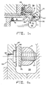
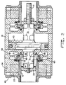
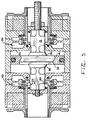
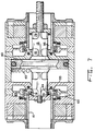
- valve actuator is illustrated sequentially in Figures 1-7 to illustrate various component locations and functions in moving a poppet valve or other component (not shown) from a closed to an open position. Motion in the opposite direction will be clearly understood from the symmetry of the components.
- a pneumatically powered valve actuator is shown having a valve actuator housing 19 and a piston 13 reciprocable within the housing along the axis of the shaft or stem 11.
- the piston 13 has a pair of oppositely facing primary working surfaces 38 and 40, a pressurized air source 39, a pair of air control valves 15 and 17 reciprocable along the axis relative to both the housing 19 and the piston 13 between open and closed positions.
- a magnetic neutralization coil 24 or 26 may be energized to neutralize the latching effect of a permanent magnet 25 or 27 for selectively opening one of the air control valves 15 or 17 to supply pressurized air from the air source to one of said primary working surfaces causing the piston to move.
- the actuator includes a shaft or stem 11 which may form a part of or connect to an internal combustion engine poppet valve.
- the actuator also includes a reciprocable piston 13, and a pair of reciprocating or sliding control valve members 15 and 17 enclosed within the housing 19.
- the control valve members 15 and 17 are latched in a closed position by a combination of the attractive forces of magnets 25 and 27, and may be dislodged from their respective latched positions by energization of coils 24 and 26.
- the control valve members or shuttle valves 15 and 17 cooperate with both the piston 13 and the housing 19 to achieve various porting functions during operation.
- the housing 19 has a high pressure inlet port 39 similar to the inlet ports of many of the above identified copending applications.
- the low pressure may be about atmospheric pressure while the high pressure is on the order of 90-100 psi. gauge pressure.
- An intermediate or latching air pressure source may, as in earlier applications, supply air at, for example, about 9-10 psi to the annular slot 43.
- Figure 1 shows an initial state with piston 13 in the extreme leftward position and with the air control valve 15 latched closed.
- the annular abutment end surface 77 is inserted into an annular slot in the housing 19 and seals against an "0"-ring 47. This seals the pressure in cavity 39 and prevents the application of any moving force to the main piston 13.
- the main piston 13 is being urged to the left (latched) by the pressure on working surface 40.
- Figure 1 illustrates the actuator with the power piston 13 latched in the far leftmost position as it would be when the corresponding engine valve is closed.
- the subpiston annular chamber 91 communicates with the low pressure outlet chamber 63 and is at atmospheric pressure when the main piston is at rest as shown.
- the subpiston 29 or 31 slidingly engages the inside bore of the air control valve 15. Permanent magnet 25 holds air control valve 15 in a closed state.
- port 23 is always open providing an air path between chambers 91 and 35, hence the two chambers increase in pressure together as the subpiston segment 29 moves toward the right applying the high control valve closing pressure equally to all the back surfaces insuring a more positive and rapid valve reclosure.
- Control valve reclosure is accomplished without the addition of any source air, however, in cases where the magnetic characteristics of the latching assembly are reduced, additional source air may be resorted to for aiding reclosure.
- additional or prepressurizing air may be obtained by a slight widening of the window 59 so that the tang or tab 77 clears the slot 45 before the edge 49 closes off communication between window 59 and chamber 91.
- the amount of such prepressurization may be controlled by source air pressure, speed of movement of the air control valve as well as window size and location.
- coil 24 is energized and the field from permanent magnet 25 is decreased until the air control valve 15 is free to move.
- Air valve 15 is accelerated from the high pressure in chamber 39 acting on control valve faces 21 and 22.
- Atmospheric port 63 no longer communicates with subpiston chamber 91 because annulus 33 has isolated the chamber 35 from the low pressure outlet port 63.
- the subpiston chamber 91 acts as a complex air spring being compressed and this increasing pressure is applied to face 49 of the air control valve 15 as well as within chamber 35.
- the motion of subpiston 29 and air valve 15 is towards each other, this makes up a nonlinear changing volume thus creating the complex air spring.
- the air valve 15 has traveled a little over one-half of its total travel in Figure 2.
- window 59 As tang 77 slides clear of the body 41 portion of the main housing 19, main piston 13 is accelerated by the high pressure from chamber 39 through window 59.
- Window 59 and the other windows to be discussed subsequently are a series of shallow peripheral undercuts in an otherwise cylindrical portion of the main piston.
- air valve 15 has traveled to its full open position. Air in subpiston chamber 91 continues to be compressed and a small amount of energy is being extracted from the main piston 13 by subpiston 29 due to the building pressure in subpiston chamber 91. Window 59 has cut off main piston 13 from the source pressure. The main piston 13 has now traveled about thirty percent of its total travel and the high pressure in main piston cylinder 81 is being expanded.
- the reed valve When the pressure on the right side 40 of the main piston reaches source pressure in chamber 39, one or more reed valves open to vent this excess pressure back into the source.
- One reed valve which is shown in detail in Figure 6a and functions as a means for selectively controlling the quantity of trapped air which is returned to the high pressure source.
- the reed valve is a one-way valve which is movable between closed and opened positions and includes an arrangement in the form of an adjustable set screw 57 for varying the distance between the closed and opened positions.
- the reed 65 has some resilience and normally rests on surface 67 so as to seal the port hole 69, but is forced away from the surface 67 by a sufficiently elevated pressure in the piston chamber to pass excess pressure air back into source chamber 39.
- the set screw 57 allows adjustment to allow greater or lesser amounts of air to pass through the reed valve thereby providing control over final damping of the piston.
- the set screw controls the separation between movable plate 73 and stationary block 71.
- the selected position of the movable plate controls the allowable opening of reed 65 and that, in turn, controls the quantity of excess pressure air which is vented from the piston chamber and, therefor, the degree of damping experienced by the piston.
- the one-way valve includes a reed which, when in the closed position, engages and covers an opening the housing along with an adjustable stop for limiting the distance the reed moves away from the opening in the housing.
- FIG. 1 A comparison of Figures 1 and 7 which illustrate the two stable states of the pneumatically powered valve actuator reveals the fact that the working cylinder within which the main piston reciprocates has a pair of opposite contoured end faces 53 and 55, and that the main piston 13 has a pair of oppositely facing primary working surfaces 38 and 40 which are contoured substantially the same as the opposed end faces of the working cylinder to mate therewith.
- the contoured end faces each include a central opening, an outer annular flat surface and an intermediate frustoconical surface 86 connecting the flat surfaces and the central opening.
- Such close mating of these surfaces results in a minimum volume which is very small helping to provide a high compression ratio for piston motion.
- the conical segment 86 improves strength at minimum mass, but more importantly, this conical segment 86 allows the axial length of the windows 59 and 61 to be short, thus of lower volume, and again improving the compression ratio of the device.
Landscapes
- Engineering & Computer Science (AREA)
- Mechanical Engineering (AREA)
- General Engineering & Computer Science (AREA)
- Fluid-Driven Valves (AREA)
- Actuator (AREA)
- Valve Device For Special Equipments (AREA)
Claims (7)
- Pneumatisch betriebenes Stellglied mit einem Stellgliedgehäuse (19), einem im Gehäuse (19) längs einer Achse hin- und herlaufenden Hauptkolben (13), mit einem Paar von Hilfskolben (29, 31), die am Hauptkolben (13) befestigt sind und mit ihm bewegbar sind, wobei der Hauptkolben (13) ein Paar einander gegenüberliegend zugewandten primären Arbeitsflächen (38, 40) enthält, mit einer unter Überdruck gehaltenen Hochdruck-Luftquelle (39), mit einer Zwischendruck-Luftquelle (43), mit einem Niederdruck-Luftauslaß (63), mit einem Paar von Luftregelventilen (15, 17), die längs der Achse in bezug sowohl auf das Gehäuse (19) als auf den Hauptkolben (13) zwischen geöffneten und geschlossenen Stellungen hin- und herlaufen können, mit einem Mittel zum selektiven Öffnen eines der Luftregelventile (15, 17) zum Liefern von Überdruckluft aus der Luftquelle (39) nach einer der primären Arbeitsflächen (38, 40), wodurch der Hauptkolben (13) und das Paar von Hilfskolben (29, 31) sich in Bewegung setzen, wobei jeder Hilfskolben (29, 31) in Zusammenarbeit mit einer Oberfläche (49) des entsprechenden Luftregelventils (15, 17) eine volumenvariable Ringkammer (91, 95) bildet, mit einem Mittel zum Ansprechen auf die Bewegung eines der Hilfskolben (29, 31) zum Befördern des einen Luftregelventils (15, 17) in seine geschlossene Stellung, wobei das auf Bewegung ansprechende Mittel die volumenvariable Ringkammer (91, 95) enthält, der Druck in der volumenvariablen Ringkammer (91, 95) zusammen mit dem einen Luftregelventil (15, 17) zunächst atmosphärischen Druckwert hat und in einer Teilzeit ansteigt, in der sich der Hauptkolben (13) bewegt, und auf atmosphärischen Druck zurückfällt, wenn das Luftregelventil (15, 17) in seine geschlossene Stellung unabhängig von der Stellung des Hauptkolbens (13) zurückkehrt, mit einem nach der einleitenden Kolbenbewegung betreibbaren und auf fortgesetzte Kolbenbewegung ansprechenden Mittel zum Komprimieren eines eingefangenen Luftvolumens, wobei die Kolbenbewegung verlangsamt wird, und mit einem Mittel zum Zurückführen eines Teils der eingefangenen Luft, die komprimiert wurde, worin das Gehäuse (19) des Stellglieds einen Arbeitszylinder (81) mit einem Paar entgegengesetzt profilierter Stirnflächen (53, 55) enthält, und die primären Arbeitsflächen (38, 40) des Hauptkolbens (13) im wesentlichen genau so profiliert ist wie die einander gegenüberliegenden Stirnflächen (53, 55) des Arbeitszylinders (81), um damit zusammenzuarbeiten.
- Pneumatisch betriebenes Stellglied nach Anspruch 1, worin die profilierten Stirnflächen (53, 55) je eine Zentralöffnung, eine äußere ebene Ringfläche und eine stumpfkegelförmige Zwischenfläche (86) enthalten, die die ebene Fläche und die Zentralöffnung miteinander verbinden.
- Pneumatisch betriebenes Stellglied nach Anspruch 1 oder 2, mit einem Mittel (79) zum Zusammenarbeiten mit einer entsprechenden volumenvariablen Ringkammer (91, 95), wenn ihr Volumen minimal ist, um einen Weg zum Ausüben von Hochdruck-Luftdruck zu bilden, um das zugeordnete Luftregelventil (15, 17) in eine geschlossene Stellung zu befördern und damit das Öffnen des Luftregelventils (15, 17) einzuleiten.
- Pneumatisch betriebenes Stellglied nach Anspruch 1, 2 oder 3, mit einem Mittel zum Zurückführen der Luft, die auf einen höheren Druck als der Druck der Hochdruckquelle komprimiert wurde, nach der Hochdruckquelle (39), und zum selektiven Regeln der eingefangenen Luftmenge, die nach der Druckquelle (39) zurückgeführt wird, wobei dieses Mittel wenigstens ein zwischen geschlossenen und geöffneten Stellungen verschiebbares Einwegventil (65) und ein Mittel (57) zum Ändern des Abstands zwischen den geschlossenen und geöffneten Stellungen enthält.
- Pneumatisch betriebenes Stellglied nach Anspruch 4, worin das Einwegventil ein Reed (65) enthält, das in der geschlossenen Stellung mit einer Öffnung im Gehäuse (19) zusammenarbeitet und diese Öffnung bedeckt, wobei das Mittel zum Ändern einen einstellbaren Anschlag (73) zum Begrenzen des Abstands enthält, über den das Reed (65) sich von der Öffnung (69) im Gehäuse (19) entfernt.
- Pneumatisch betriebenes Stellglied nach einem der Ansprüche 1 bis 5, weiter mit einem federnden Mittel (51) aufjedem Hilfskolben (29, 31) zum Zusammenarbeiten mit dem entsprechenden Luftregelventil (15, 17) und zum Schließen dieses Ventils, wenn der Druck in der volumenvariablen Kammer (91, 95) nicht imstande ist, das Luftregelventil (15, 17) zu schließen.
- Pneumatisch betriebenes Stellglied nach einem oder mehreren der vorangehenden Ansprüche, mit einem Paar ringförmiger Unterkammern (35, 99), die den volumenvariablen Ringkammern (91, 95) zugeordnet sind, wobei jede Unterkammer (35, 99) zum Teil durch das zugeordnete Luftregelventil (15, 17) begrenzt und dahin angepaßt wird, daß sie mit der zugeordneten volumenvariablen Ringkammer (91, 95) und mit dem Niederdruck-Luftauslaß (63) vorübergehend kommuniziert.
Applications Claiming Priority (2)
| Application Number | Priority Date | Filing Date | Title |
|---|---|---|---|
| US07/294,727 US4915015A (en) | 1989-01-06 | 1989-01-06 | Pneumatic actuator |
| US294727 | 1989-01-06 |
Publications (2)
| Publication Number | Publication Date |
|---|---|
| EP0377254A1 EP0377254A1 (de) | 1990-07-11 |
| EP0377254B1 true EP0377254B1 (de) | 1993-12-08 |
Family
ID=23134676
Family Applications (1)
| Application Number | Title | Priority Date | Filing Date |
|---|---|---|---|
| EP89203294A Expired - Lifetime EP0377254B1 (de) | 1989-01-06 | 1989-12-21 | Pneumatisches Stellglied |
Country Status (5)
| Country | Link |
|---|---|
| US (1) | US4915015A (de) |
| EP (1) | EP0377254B1 (de) |
| JP (1) | JPH02236008A (de) |
| CA (1) | CA2007297A1 (de) |
| DE (1) | DE68911286T2 (de) |
Families Citing this family (14)
| Publication number | Priority date | Publication date | Assignee | Title |
|---|---|---|---|---|
| US5003938A (en) * | 1989-12-26 | 1991-04-02 | Magnavox Government And Industrial Electronics Company | Pneumatically powered valve actuator |
| US5029516A (en) * | 1989-12-26 | 1991-07-09 | North American Philips Corporation | Pneumatically powered valve actuator |
| US5022359A (en) * | 1990-07-24 | 1991-06-11 | North American Philips Corporation | Actuator with energy recovery return |
| US5109812A (en) * | 1991-04-04 | 1992-05-05 | North American Philips Corporation | Pneumatic preloaded actuator |
| US5193495A (en) * | 1991-07-16 | 1993-03-16 | Southwest Research Institute | Internal combustion engine valve control device |
| US5259345A (en) * | 1992-05-05 | 1993-11-09 | North American Philips Corporation | Pneumatically powered actuator with hydraulic latching |
| JP3368518B2 (ja) * | 1995-06-30 | 2003-01-20 | 三菱自動車工業株式会社 | 多段開度弁装置 |
| DE19723924B4 (de) * | 1997-06-06 | 2008-02-28 | Hoffmann, Bernhard | Elektrischer Linearmotor |
| DE102004043548B4 (de) * | 2004-09-09 | 2013-04-18 | Daimler Ag | Vorrichtung zur Winkelverstellung zwischen zwei rotierenden, antriebsverbundenen Elementen |
| DE102005017482B4 (de) * | 2005-04-15 | 2007-05-03 | Compact Dynamics Gmbh | Gaswechselventilaktor für einen ventilgesteuerten Verbrennungsmotor |
| DE102005017483B4 (de) * | 2005-04-15 | 2007-04-05 | Compact Dynamics Gmbh | Linearaktor in einem Elektro-Schlagwerkzeug |
| DE102005017481B4 (de) * | 2005-04-15 | 2007-08-30 | Compact Dynamics Gmbh | Linearaktor |
| KR101035101B1 (ko) | 2011-03-31 | 2011-05-19 | 한국뉴매틱(주) | 이단 에어콘트롤 밸브 |
| KR102225162B1 (ko) | 2020-06-19 | 2021-03-09 | (주)브이텍 | 진공 시스템용 에어-밸브 유닛 |
Family Cites Families (9)
| Publication number | Priority date | Publication date | Assignee | Title |
|---|---|---|---|---|
| DE421002C (de) * | 1925-11-04 | D Aviat Louis Breguet Sa Des A | Steuerung von Ventilen, insbesondere fuer Explosionsmotoren, durch Fluessigkeiten oder Gase | |
| DE197808C (de) * | ||||
| FR2557949B1 (fr) * | 1984-01-09 | 1986-10-03 | Joucomatic | Perfectionnements apportes aux v |
| JPS62136680U (de) * | 1986-02-21 | 1987-08-28 | ||
| US4777915A (en) * | 1986-12-22 | 1988-10-18 | General Motors Corporation | Variable lift electromagnetic valve actuator system |
| JPH0794845B2 (ja) * | 1987-02-24 | 1995-10-11 | 本田技研工業株式会社 | 差圧応動式アクチュエータ |
| US4741364A (en) * | 1987-06-12 | 1988-05-03 | Deere & Company | Pilot-operated valve with load pressure feedback |
| DE3733441C1 (en) * | 1987-10-02 | 1988-12-29 | Bayerische Motoren Werke Ag | Non-return valve device in the intake port of a quantity-controlled internal combustion engine |
| US4852528A (en) * | 1988-06-20 | 1989-08-01 | Magnavox Government And Industrial Electronics Company | Pneumatic actuator with permanent magnet control valve latching |
-
1989
- 1989-01-06 US US07/294,727 patent/US4915015A/en not_active Expired - Fee Related
- 1989-12-21 DE DE68911286T patent/DE68911286T2/de not_active Expired - Fee Related
- 1989-12-21 EP EP89203294A patent/EP0377254B1/de not_active Expired - Lifetime
-
1990
- 1990-01-05 JP JP2000128A patent/JPH02236008A/ja active Pending
- 1990-01-08 CA CA002007297A patent/CA2007297A1/en not_active Abandoned
Also Published As
| Publication number | Publication date |
|---|---|
| CA2007297A1 (en) | 1990-07-06 |
| EP0377254A1 (de) | 1990-07-11 |
| JPH02236008A (ja) | 1990-09-18 |
| DE68911286D1 (de) | 1994-01-20 |
| US4915015A (en) | 1990-04-10 |
| DE68911286T2 (de) | 1994-05-26 |
Similar Documents
| Publication | Publication Date | Title |
|---|---|---|
| US4852528A (en) | Pneumatic actuator with permanent magnet control valve latching | |
| US4883025A (en) | Potential-magnetic energy driven valve mechanism | |
| US4831973A (en) | Repulsion actuated potential energy driven valve mechanism | |
| EP0377254B1 (de) | Pneumatisches Stellglied | |
| US5058538A (en) | Hydraulically propelled phneumatically returned valve actuator | |
| EP0377244B1 (de) | Schnell arbeitendes Ventil | |
| US4942852A (en) | Electro-pneumatic actuator | |
| US4873948A (en) | Pneumatic actuator with solenoid operated control valves | |
| US5022359A (en) | Actuator with energy recovery return | |
| US4899700A (en) | Pneumatically powered valve actuator | |
| US4991548A (en) | Compact valve actuator | |
| EP0377250B1 (de) | Ventilstellglied mit verbesserter Leistung | |
| US4872425A (en) | Air powered valve actuator |
Legal Events
| Date | Code | Title | Description |
|---|---|---|---|
| PUAI | Public reference made under article 153(3) epc to a published international application that has entered the european phase |
Free format text: ORIGINAL CODE: 0009012 |
|
| AK | Designated contracting states |
Kind code of ref document: A1 Designated state(s): DE ES FR GB IT SE |
|
| 17P | Request for examination filed |
Effective date: 19901219 |
|
| 17Q | First examination report despatched |
Effective date: 19920319 |
|
| RAP1 | Party data changed (applicant data changed or rights of an application transferred) |
Owner name: MAGNAVOX ELECTRONIC SYSTEMS COMPANY |
|
| GRAA | (expected) grant |
Free format text: ORIGINAL CODE: 0009210 |
|
| AK | Designated contracting states |
Kind code of ref document: B1 Designated state(s): DE ES FR GB IT SE |
|
| PG25 | Lapsed in a contracting state [announced via postgrant information from national office to epo] |
Ref country code: SE Effective date: 19931208 Ref country code: ES Free format text: THE PATENT HAS BEEN ANNULLED BY A DECISION OF A NATIONAL AUTHORITY Effective date: 19931208 |
|
| PGFP | Annual fee paid to national office [announced via postgrant information from national office to epo] |
Ref country code: GB Payment date: 19931208 Year of fee payment: 5 |
|
| PGFP | Annual fee paid to national office [announced via postgrant information from national office to epo] |
Ref country code: FR Payment date: 19931222 Year of fee payment: 5 |
|
| REF | Corresponds to: |
Ref document number: 68911286 Country of ref document: DE Date of ref document: 19940120 |
|
| ITF | It: translation for a ep patent filed | ||
| PGFP | Annual fee paid to national office [announced via postgrant information from national office to epo] |
Ref country code: DE Payment date: 19940223 Year of fee payment: 5 |
|
| ET | Fr: translation filed | ||
| PLBE | No opposition filed within time limit |
Free format text: ORIGINAL CODE: 0009261 |
|
| STAA | Information on the status of an ep patent application or granted ep patent |
Free format text: STATUS: NO OPPOSITION FILED WITHIN TIME LIMIT |
|
| 26N | No opposition filed | ||
| PG25 | Lapsed in a contracting state [announced via postgrant information from national office to epo] |
Ref country code: GB Effective date: 19941221 |
|
| GBPC | Gb: european patent ceased through non-payment of renewal fee |
Effective date: 19941221 |
|
| PG25 | Lapsed in a contracting state [announced via postgrant information from national office to epo] |
Ref country code: FR Effective date: 19950831 |
|
| PG25 | Lapsed in a contracting state [announced via postgrant information from national office to epo] |
Ref country code: DE Effective date: 19950901 |
|
| REG | Reference to a national code |
Ref country code: FR Ref legal event code: ST |
|
| PG25 | Lapsed in a contracting state [announced via postgrant information from national office to epo] |
Ref country code: IT Free format text: LAPSE BECAUSE OF NON-PAYMENT OF DUE FEES;WARNING: LAPSES OF ITALIAN PATENTS WITH EFFECTIVE DATE BEFORE 2007 MAY HAVE OCCURRED AT ANY TIME BEFORE 2007. THE CORRECT EFFECTIVE DATE MAY BE DIFFERENT FROM THE ONE RECORDED. Effective date: 20051221 |