EP0376377A2 - Method of pneumatically inserting a cable in a sheath - Google Patents
Method of pneumatically inserting a cable in a sheath Download PDFInfo
- Publication number
- EP0376377A2 EP0376377A2 EP89203222A EP89203222A EP0376377A2 EP 0376377 A2 EP0376377 A2 EP 0376377A2 EP 89203222 A EP89203222 A EP 89203222A EP 89203222 A EP89203222 A EP 89203222A EP 0376377 A2 EP0376377 A2 EP 0376377A2
- Authority
- EP
- European Patent Office
- Prior art keywords
- cross
- line
- winding
- cross wrap
- sheath
- Prior art date
- Legal status (The legal status is an assumption and is not a legal conclusion. Google has not performed a legal analysis and makes no representation as to the accuracy of the status listed.)
- Granted
Links
Images
Classifications
-
- G—PHYSICS
- G02—OPTICS
- G02B—OPTICAL ELEMENTS, SYSTEMS OR APPARATUS
- G02B6/00—Light guides; Structural details of arrangements comprising light guides and other optical elements, e.g. couplings
- G02B6/44—Mechanical structures for providing tensile strength and external protection for fibres, e.g. optical transmission cables
- G02B6/4479—Manufacturing methods of optical cables
- G02B6/4485—Installing in protective tubing by fluid drag during manufacturing
-
- H—ELECTRICITY
- H02—GENERATION; CONVERSION OR DISTRIBUTION OF ELECTRIC POWER
- H02G—INSTALLATION OF ELECTRIC CABLES OR LINES, OR OF COMBINED OPTICAL AND ELECTRIC CABLES OR LINES
- H02G1/00—Methods or apparatus specially adapted for installing, maintaining, repairing or dismantling electric cables or lines
- H02G1/06—Methods or apparatus specially adapted for installing, maintaining, repairing or dismantling electric cables or lines for laying cables, e.g. laying apparatus on vehicle
- H02G1/08—Methods or apparatus specially adapted for installing, maintaining, repairing or dismantling electric cables or lines for laying cables, e.g. laying apparatus on vehicle through tubing or conduit, e.g. rod or draw wire for pushing or pulling
- H02G1/086—Methods or apparatus specially adapted for installing, maintaining, repairing or dismantling electric cables or lines for laying cables, e.g. laying apparatus on vehicle through tubing or conduit, e.g. rod or draw wire for pushing or pulling using fluid as pulling means, e.g. liquid, pressurised gas or suction means
-
- G—PHYSICS
- G02—OPTICS
- G02B—OPTICAL ELEMENTS, SYSTEMS OR APPARATUS
- G02B6/00—Light guides; Structural details of arrangements comprising light guides and other optical elements, e.g. couplings
- G02B6/46—Processes or apparatus adapted for installing or repairing optical fibres or optical cables
- G02B6/50—Underground or underwater installation; Installation through tubing, conduits or ducts
- G02B6/52—Underground or underwater installation; Installation through tubing, conduits or ducts using fluid, e.g. air
Definitions
- the invention relates to a method for blowing a line into an empty envelope, in which the line is drawn off from a supply roll and conveyed into the empty envelope by means of compressed air blown into the empty envelope.
- the invention has for its object to simplify the method of the type mentioned and to enable trouble-free drainage of the line from a supply roll even at high take-off speeds.
- the solution is achieved in that the supply roll consists of a self-supporting cross roll without a roll body.
- the line can contain at least one electrical conductor or at least one optical waveguide (LWL).
- LWL optical waveguide
- a cross wrap used in accordance with the invention can be produced at the end of the line production. It can then be used directly on site without any wrapping measures to blow the line into an empty shell.
- Such a cross wrap forms a self-supporting stable unit without any supporting body and enables the storage of a long line length in a small volume.
- the line can be pulled off without interference, without jamming.
- the required withdrawal forces are particularly low, so that the conveying forces caused by the compressed air are usually sufficient without additional mechanical conveying devices.
- the cross wrap according to the invention can be arranged in a container which can be pressurized with compressed air via a feed opening and has an outlet opening for connecting the empty casing.
- the main advantage here is that the line does not have to be introduced into a container charged with compressed air via an inlet channel to be sealed and therefore causing additional frictional force.
- the cross wrap can be produced with a particularly well-structured structure if the line has a sheath surrounding its conductor, which has a flattened cross-sectional contour widened in the direction of the winding plane when the cross wrap is connected, particularly at the crossing points of the windings.
- a solution that is easy to manufacture is characterized in that the winding is wound with a line whose circular sheath has an elastic modulus of less than 1 GPa.
- the originally circular shell deforms into the desired flat shape during the winding process.
- Materials with a low modulus of elasticity of less than 1 GPa are suitable for this, such as in particular thermoplastic polyurethane or soft polyvinyl chloride.
- the conductor is surrounded by a tubular sheath at a distance. This results in the desired flat cross-sectional contour even when using harder materials for the casing during the winding process.
- a gel-like mass is introduced between the tube-like sheath and the conductor or optical fiber.
- a gel-like mass which has the known advantages allows the desired deformation of the tubular casing to a flat cross-sectional contour.
- Relatively hard materials such as, in particular, polybutylene terephthalate and elastomer-modified polybutylene terephthalate can be used for the plastic casing.
- Polyamides have also proven to be advantageously suitable.
- At least one strain relief element in particular in the form of at least one fiber-like element, to be additionally arranged within the casing, in particular in the case of an optical fiber.
- An advantageous possibility of fixing a line with an optical fiber in its position in the winding consists in that a metal wire which is plastically deformed during the winding process is additionally arranged within the sheath.
- the holding forces of polar materials e.g. polyurethane
- the slope angle of the line relative to a cross-sectional plane of the cross wrap should be as large as possible for reasons of stability, but on the other hand as small as possible to enable the line to be pulled off quickly and without problems.
- the pitch angle of a line relative to a cross-sectional plane of the package in each winding position is in the range from 2 o to 30 o , preferably in the range from 4 o to 10 o .
- a production method which is advantageous for this embodiment of the cross wrap is characterized in that, depending on the respective diameter of the cross wrap achieved during the winding process, the pitch angle is adjusted such that it is in the range from 2 o to 30 o , preferably in the range from 4 o to 10 o .
- the adjustment of the pitch angle makes it possible to produce coils with a high number of layers while observing the abovementioned limits for the pitch angle. This prevents the pitch angle from decreasing steadily with increasing winding diameter, which would make the winding unstable.
- the fiber optic core is wound with a torsion over the entire length.
- a counter-compensating torsion is applied during the manufacture of the roll, so that the line that is pulled off is torsion-free.
- the flat form of the line which is advantageous in terms of winding technology, can be achieved in a particularly simple manner without additional measures by winding it with a multiple line which consists of a plurality of individual lines connected to one another.
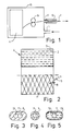
- Fig. 1 the end region of an empty envelope 13 (for example extruded plastic tube or steel tube) is indicated, into which a line 1, for example a coated fiber optic cable or an insulated electrical conductor, is to be blown.
- a container 15 is supplied with compressed air via the supply line 14, in which a container 15 is inserted
- Cross winding 4 is introduced with the required supply of line 1. If necessary, the withdrawal of line 1 into the empty envelope 13 can be supported by conveyor wheels 16.
- the empty envelope is sealed to the outlet connector 17 of the container 15.
- the pitch angle of the turns 1 with respect to a cross-sectional plane of the cross wrap 4 was set in all layers to a value which deviates only slightly from 8 o .
- the ratio of the winding speed and the speed of the axial guidance of the line 1 was changed in constant adaptation, so that the angle was kept within the range from 4 o to 10 o . Such an adjustment can take place continuously. In the preferred exemplary embodiment, this was done in stages after the production of a few winding layers, since a certain fluctuation range of the pitch angle is permitted.
- FIGS. 3, 4 and 5 Different cross-sectional shapes of a fiber-optic line 1 can be seen enlarged in FIGS. 3, 4 and 5 compared to position 3 in FIG. 2.
- the FO 6.7 or 8 have a diameter of about 250 ⁇ m including their plastic coating. They are surrounded by extruded sleeves 9, 10 and 11 respectively.
- a plastically deformable metal wire 13 is arranged in the plastic sleeve 11 parallel to the FO 8. The result is a flattened cross-sectional shape, which facilitates the winding of an even cheese.
- the plastically deformable metal wire 13 also maintains the winding position of the wire according to FIG. 2 against the elastic restoring forces of the optical fiber 8 at reversal points of the winding pitch, even if the surface of the plastic sleeve 11 is relatively smooth and adhesive-free.
- the optical fiber 6 is only surrounded by a particularly soft and not too thin plastic sheath, which is deformed into an elongated cross section similar to FIGS. 2 and 4 during winding of the package, so that it is at least approximately the same good winding results are achieved, as in the case of an elongated cross-sectional shape that was already present.
- plastics with an elastic modulus of less than 1 GPa have proven to be advantageously suitable. That is why thermoplastic polyurethane or soft polyvinyl chloride have been used in particular.
- stiffer shells 10 can be used, since the flexibility of the cross-sectional shape is achieved by a gel-like intermediate layer 12, which additionally prevents the attenuation increases in the optical fiber.
- FIG. 5 shows the cross-sectional shape that arises in the cross wrap. Originally, a circular plastic sheath 12 was extruded around the FO 7 concentrically.
- the cross wrap holds together excellently even without adhesive coating of the wires and can be unwound at high speed without problems.
Abstract
Die Erfindung betrifft ein Verfahren zum Einblasen einer Leitung (1) in eine Leerhülle (13), bei welchem die Leitung (1) von einem Vorratswickel abgezogen und mittels in die Leerhülle (13) geblasener Druckluft in die Leerhülle (13) gefördert wird. Auch bei schnellen Abzugsgeschwindigkeiten wird ein störungsfreier Ablauf der Leitung aus dem Wickel dadurch ermöglicht, daß der Vorratswickel aus einem wickelkörperlosen selbsttragenden Kreuzwickel (4) besteht.The invention relates to a method for blowing a line (1) into an empty envelope (13), in which the line (1) is drawn off from a supply roll and conveyed into the empty envelope (13) by means of compressed air blown into the empty envelope (13). Even at fast take-off speeds, trouble-free drainage of the line from the roll is made possible by the supply roll consisting of a self-supporting cross roll (4) without a roll body.
Description
Die Erfindung bezieht sich auf ein Verfahren zum Einblasen einer Leitung in eine Leerhülle, bei welchem die Leitung von einem Vorratswickel abgezogen und mittels in die Leerhülle geblasener Druckluft in die Leerhülle gefördert wird.The invention relates to a method for blowing a line into an empty envelope, in which the line is drawn off from a supply roll and conveyed into the empty envelope by means of compressed air blown into the empty envelope.
Bei einem in Br.Telecom Technol. 87, Seiten 20 bis 24 beschriebenen derartigen Verfahren wird eine optische Leitung zunächst mit losen Windungen in einen Aufnahmebehälter gelegt, wobei eine Torsionsumdrehung pro Windung vorgesehen ist. Aus diesem Aufnahmebehälter wird die Leitung beim Einblasen in eine Kabelhülle ohne Drehung des Aufnahmebehälters abgezogen. Dabei brauchen keine großen Massen beschleunigt zu werden. Mit dem Einblasverfahren können Leitungen in Kanäle oder Leerhüllen eines Kabels in beträchtlicher Länge eingezogen werden. Für den Abzug der Leitung sind spezielle und störungsempfindliche Führungseinrichtungen erforderlich. Bei höheren Abzugsgeschwindigkeiten können die frei im Aufnahmebehälter gegeneinander verschiebbaren Windungen verrutschen und verklemmen.In one in Br.Telecom Technol. 87, pages 20 to 24 of such methods, an optical line is first laid with loose turns in a receptacle, one torsion revolution per turn being provided. The line is pulled out of this receptacle when it is blown into a cable sheath without rotating the receptacle. No large masses need to be accelerated. The blow-in process allows cables to be drawn into channels or empty sheaths of a considerable length. Special and fault-sensitive guide devices are required to pull off the line. At higher take-off speeds, the windings, which are freely displaceable in the receiving container, can slip and jam.
Der Erfindung liegt die Aufgabe zugrunde, das Verfahren der eingangs genannten Art zu vereinfachen und auch bei hohen Abzugsgeschwindigkeiten einen störungsfreien Ablauf der Leitung aus einem Vorratswickel zu ermöglichen.The invention has for its object to simplify the method of the type mentioned and to enable trouble-free drainage of the line from a supply roll even at high take-off speeds.
Die Lösung gelingt dadurch, daß der Vorratswickel aus einem wickelkörperlosen selbsttragenden Kreuzwickel besteht.The solution is achieved in that the supply roll consists of a self-supporting cross roll without a roll body.
Die Leitung kann mindestens einen elektrischen Leiter oder mindestens einen Lichtwellenleiter (LWL) enthalten.The line can contain at least one electrical conductor or at least one optical waveguide (LWL).
Ein erfindungsgemäß verwendeter Kreuzwickel kann zum Abschluß der Leitungsfertigung hergestellt werden. Er kann danach vor Ort ohne Umwickelmaßnahmen direkt für das Einblasen der Leitung in eine Leerhülle verwendet werden. Ein solcher Kreuzwickel bildet ohne jeglichen Tragkörper eine frei tragende stabile Einheit und ermöglicht die Speicherung einer hohen Leitungslänge in kleinem Volumen. Bei hohen Abzugsgeschwindigkeiten kann die Leitung störungsfrei abgezogen werden, ohne daß Verklemmungen entstehen. Die erforderlichen Abzugskräfte sind besonders gering, so daß meist ohne zusätzliche mechanische Fördereinrichtungen allein die durch die Druckluft bewirkten Förderkräfte ausreichen.A cross wrap used in accordance with the invention can be produced at the end of the line production. It can then be used directly on site without any wrapping measures to blow the line into an empty shell. Such a cross wrap forms a self-supporting stable unit without any supporting body and enables the storage of a long line length in a small volume. At high take-off speeds, the line can be pulled off without interference, without jamming. The required withdrawal forces are particularly low, so that the conveying forces caused by the compressed air are usually sufficient without additional mechanical conveying devices.
Da keine speziellen Aufnahmebehälter für den Kreuzwickel erforderlich sind, kann der erfindungsgemäße Kreuzwickel in einem Behälter angeordnet werden, welcher über eine Zuführungsöffnung mit Druckluft beaufschlagbar ist und eine Auslaßöffnung zum Anschluß der Leerhülle aufweist. Dabei ergibt sich der wesentliche Vorteil, daß die Leitung nicht über einen abzudichtenden und deshalb zusätzliche Reibungskraft verursachenden Einlaufkanal in einen mit Druckluft beaufschlagten Behälter eingeführt werden muß.Since no special receptacles are required for the cross wrap, the cross wrap according to the invention can be arranged in a container which can be pressurized with compressed air via a feed opening and has an outlet opening for connecting the empty casing. The main advantage here is that the line does not have to be introduced into a container charged with compressed air via an inlet channel to be sealed and therefore causing additional frictional force.
Der Kreuzwickel kann mit einem besonders gut geordneten Aufbau hergestellt werden, wenn die Leitung eine ihren Leiter umgebende Hülle aufweist, welche im Verband des Kreuzwickels, insbesondere an den Kreuzungsstellen der Windungen eine in Richtung der Wickelebene verbreiterte abgeflachte Querschnittskontur aufweist.The cross wrap can be produced with a particularly well-structured structure if the line has a sheath surrounding its conductor, which has a flattened cross-sectional contour widened in the direction of the winding plane when the cross wrap is connected, particularly at the crossing points of the windings.
Eine einfach herstellbare Lösung ist dadurch gekennzeichnet, daß der Wickel mit einer Leitung gewickelt ist, deren kreisrunde Hülle einen E-Modul von kleiner als 1 GPa aufweist. Die ursprünglich kreisrunde Hülle verformt sich beim Wickelvorgang in die gewünschte flache Form. Dafür sind Stoffe mit einem geringen E-Modul von weniger als 1 GPa geeignet, wie insbesondere thermoplastisches Polyurethan oder Weich-Polyvinylchlorid.A solution that is easy to manufacture is characterized in that the winding is wound with a line whose circular sheath has an elastic modulus of less than 1 GPa. The originally circular shell deforms into the desired flat shape during the winding process. Materials with a low modulus of elasticity of less than 1 GPa are suitable for this, such as in particular thermoplastic polyurethane or soft polyvinyl chloride.
Gemäß einer besonders vorteilhaften Lösung ist vorgesehen, daß der Leiter mit Abstand von einer schlauchartigen Hülle umgeben ist. Dabei ergibt sich selbst bei Verwendung von härteren Werkstoffen für die Hülle beim Wickelvorgang die gewünschte flache Querschnittskontur. Dabei wird insbesondere bei einem LWL bevorzugt, daß zwischen die schlauchartige Hülle und den Leiter bzw. LWL eine gelartige Masse eingebracht ist. Eine die an sich bekannten Vorteile aufweisende gelartige Masse läßt dabei die gewünschte Verformung der schlauchartigen Hülle zu einer flachen Querschnittskontur zu. Im Gegensatz zu einer festen Umhüllung werden bei der letzgenannten Lösung im Falle eines LWL geringere Dämpfungserhöhungen verursacht. Für die Kunststoffhülle können relativ harte Werkstoffe verwendet werden wie insbesondere Polybutylenterephthalat und elastomer-modifiziertes Polybutylenterephthalat. Auch Polyamide haben sich als vorteilhaft geeignet erwiesen.According to a particularly advantageous solution, it is provided that the conductor is surrounded by a tubular sheath at a distance. This results in the desired flat cross-sectional contour even when using harder materials for the casing during the winding process. It is particularly preferred in the case of an optical fiber that a gel-like mass is introduced between the tube-like sheath and the conductor or optical fiber. A gel-like mass which has the known advantages allows the desired deformation of the tubular casing to a flat cross-sectional contour. In contrast to a fixed envelope, the latter solution results in lower attenuation increases in the case of an optical fiber. Relatively hard materials such as, in particular, polybutylene terephthalate and elastomer-modified polybutylene terephthalate can be used for the plastic casing. Polyamides have also proven to be advantageously suitable.
Es ist ohne weiteres möglich, daß innerhalb der Hülle, insbesondere bei einem LWL, zusätzlich mindestens ein Zugentlastungselement, insbesondere in Form mindestens eines faserartigen Elements angeordnet ist.It is readily possible for at least one strain relief element, in particular in the form of at least one fiber-like element, to be additionally arranged within the casing, in particular in the case of an optical fiber.
Eine vorteilhafte Möglichkeit, eine Leitung mit einem LWL in ihrer Lage im Wickel zu fixieren, besteht darin, daß innerhalb der Hülle zusätzlich ein sich beim Wickelvorgang plastisch verformender Metalldraht angeordnet ist.An advantageous possibility of fixing a line with an optical fiber in its position in the winding consists in that a metal wire which is plastically deformed during the winding process is additionally arranged within the sheath.
Die Lagesicherung der Leitung im Wickel wird weiterhin dadurch erhöht, daß der Reibungskoeffizient der Hülle größer als u = 0,3 ist. Zusätzlich können die Haltekräfte polarer Werkstoffe (z.B. Polyurethan) zum Zusammenhalt des Wickels beitragen.The position of the line in the winding is further increased by the fact that the coefficient of friction of the sleeve is greater than u = 0.3. In addition, the holding forces of polar materials (e.g. polyurethane) can help hold the winding together.
Es hat sich gezeigt, daß der Steigungswinkel der Leitung relativ zu einer Querschnittsebene des Kreuzwickels aus Stabilitätsgründen möglichst groß sein sollte, andererseits aber möglichst klein, um ein schnelles störungsfreies Abziehen der Leitung zu ermöglichen. Als vorteilhafte Kompromißlösung ist vorgesehen, daß der Steigungswinkel einer Leitung relativ zu einer Querschnittsebene der Kreuzspule in jeder Wickellage im Bereich von 2o bis 30o, vorzugsweise im Bereich von 4o bis 10o liegt.It has been shown that the slope angle of the line relative to a cross-sectional plane of the cross wrap should be as large as possible for reasons of stability, but on the other hand as small as possible to enable the line to be pulled off quickly and without problems. As an advantageous compromise solution it is provided that the pitch angle of a line relative to a cross-sectional plane of the package in each winding position is in the range from 2 o to 30 o , preferably in the range from 4 o to 10 o .
Ein für diese Ausführungsform des Kreuzwickels vorteilhaftes Herstellungsverfahren ist dadurch gekennzeichnet, daß in Abhängigkeit vom beim Wickelvorgang erreichten jeweiligen Durchmesser des Kreuzwickels der Steigungswinkel derart nachgestellt wird, daß er im Bereich von 2o bis 30o, vorzugsweise im Bereich von 4o bis 10o liegt.A production method which is advantageous for this embodiment of the cross wrap is characterized in that, depending on the respective diameter of the cross wrap achieved during the winding process, the pitch angle is adjusted such that it is in the range from 2 o to 30 o , preferably in the range from 4 o to 10 o .
Die Nachstellung des Steigungswinkels erlaubt es, auch Spulen mit hohen Lagezahlen unter Einhaltung der vorgenannten Grenzen für den Steigungswinkel herzustellten. Derart wird verhindert, daß der Steigungswinkel mit zunehmendem Wickeldurchmesser stetig abnimmt, wodurch der Wickel instabil würde.The adjustment of the pitch angle makes it possible to produce coils with a high number of layers while observing the abovementioned limits for the pitch angle. This prevents the pitch angle from decreasing steadily with increasing winding diameter, which would make the winding unstable.
Beim Abwickelvorgang der Leitung von einem nicht drehenden Wickel entstehen Torsionen. Deshalb ist vorgesehen, daß die LWL-Ader im Wickel über die gesamte Länge mit einer Torsion gewickelt ist.When the line is unwound from a non-rotating winding, torsion occurs. It is therefore envisaged that the fiber optic core is wound with a torsion over the entire length.
Bei der Herstellung des Wickels wird dabei eine gegenkompensierende Torsion aufgebracht, so daß die abgezogene Leitung torsionsfrei ist.A counter-compensating torsion is applied during the manufacture of the roll, so that the line that is pulled off is torsion-free.
Besonders einfach läßt sich die wickeltechnisch vorteilhafte flache Form der Leitung ohne zusätzliche Maßnahmen bereits dadurch erreichen, daß er mit einer Mehrfachleitung gewickelt ist, die aus mehreren nebeneinander verbundenen Einzelleitungen besteht.The flat form of the line, which is advantageous in terms of winding technology, can be achieved in a particularly simple manner without additional measures by winding it with a multiple line which consists of a plurality of individual lines connected to one another.
Die Erfindung wird anhand der Beschreibung von in der Zeichnung dargestellten vorteilhaften Ausführungsbeispielen näher erläutert.
- Fig. 1 zeigt schematisch eine Vorrichtung zur Ausübung des erfindungsgemäßen Verfahrens.
- Fig. 2 zeigt die Seitenansicht einer Kreuzspule nach Fig. 1, zur Hälfte geschnitten.
- Fig. 3 zeigt den Querschnitt eine Leitung, welche im Ausgangszustand eine verbreiterte Umhüllung aufweist.
- Fig. 4 zeigt den Querschnitt einer Leitung mit im Ausgangszustand kreisrunder weicher Kunststoffumhüllung.
- Fig. 5 zeigt eine sich im gewickelten Zustand einstellende Querschnittsform eines mit einer Gelzwischenschicht und einer Kunststoffhülle umgebenen LWL.
- Fig. 1 shows schematically an apparatus for performing the method according to the invention.
- Fig. 2 shows the side view of a package according to Fig. 1, cut in half.
- Fig. 3 shows the cross section of a line which has a widened covering in the initial state.
- Fig. 4 shows the cross section of a line with a circular soft plastic covering in the initial state.
- FIG. 5 shows a cross-sectional shape of an optical fiber surrounded by a gel intermediate layer and a plastic sheath.
In Fig. 1 ist der Endbereich einer Leerhülle 13 (z.B. extrudierter Kunststoffschlauch oder Stahlröhrchen) angedeutet, in welche eine Leitung 1, z.B. ein umhüllter LWL oder ein isolierter elektrischer Leiter eingeblasen werden soll. Dazu dient ein über die Zuleitung 14 mit Druckluft beaufschlagter Behälter 15, in welchen ein Kreuzwickel 4 mit dem erforderlichen Vorrat der Leitung 1 eingebracht ist. Bei Bedarf kann der Abzug der Leitung 1 in die Leerhülle 13 durch Förderräder 16 unterstützt werden.In Fig. 1, the end region of an empty envelope 13 (for example extruded plastic tube or steel tube) is indicated, into which a line 1, for example a coated fiber optic cable or an insulated electrical conductor, is to be blown. For this purpose, a
Die Leerhülle ist abgedichtet mit dem Auslaßstutzen 17 des Behälters 15 verbunden.The empty envelope is sealed to the
Bei dem in Figur 2 schematisch und nicht maßstäblich gezeichneten Kreuzwickel 4 ist in der unteren Hälfte der für einen Kreuzwickel typische Verlauf der Windungen einer Leitung 1 erkennbar, welche mit einem Steigungswinkel gewickelt sind. In der im Längsschnitt angedeuteten oberen Hälfte sind durch gestrichelte Linien 2 Wickelebenen einer Vielzahl von radial übereinanderliegenden Wickellagen angedeutet. Von der äußersten Wickellage sind Querschnittsformen 3 der Leitung 1 erkennbar. Die breiteren Querschnittsseiten erstrecken sich in Richtung der Ebenen ihrer Wickellagen.In the
Der Steigungswinkel der Windungen 1 gegenüber einer Querschnittsebene des Kreuzwickels 4 wurde in allen Lagen auf einen von 8o nur wenig abweichenden Wert eingestellt. Dabei wurde das Verhältnis der Wickeldrehzahl und der Geschwindigkeit der axialen Führung der Leitung 1 in ständiger Anpassung geändert, so daß der Winkel innerhalb des Bereiches von 4o bis 10o gehalten wurde. Eine solche Anpassung kann stetig erfolgen. Sie erfolgte im bevorzugten Ausführungsbeispiel stufig nach Herstellung jeweils einiger Wickellagen, da ein gewisser Schwankungsbereich des Steigungswinkels erlaubt ist.The pitch angle of the turns 1 with respect to a cross-sectional plane of the
Verschiedene Querschnittsformen einer LWL enthaltenden Leitung 1 sind gegenüber Position 3 in Fig. 2 vergrößert in den Figuren 3,4 und 5 erkennbar. Die LWL 6,7 bzw. 8 haben einschließlich ihres Kunststoffcoatings einen Durchmesser von etwa 250 um. Sie sind von aufextrudierten Hüllen 9,10 bzw. 11 umgeben.Different cross-sectional shapes of a fiber-optic line 1 can be seen enlarged in FIGS. 3, 4 and 5 compared to
Bei der Ausführungsform nach Fig. 3 ist parallel zum LWL 8 ein plastisch verformbarer Metalldraht 13 in der Kunststoffhülle 11 angeordnet. Es ergibt sich eine abgeflachte Querschnittsform, welche das Wickeln einer gleichmäßigen Kreuzspule erleichtert. Der plastisch verformbare Metalldraht 13 hält die Wickellage der Ader nach Fig. 2 entgegen der elastischen Rückstellkräfte des LWL 8 auch an Umkehrstellen der Wickelsteigung bei, selbst wenn die Oberfläche der Kunststoffhülle 11 relativ glatt und klebefrei ist.In the embodiment according to FIG. 3, a plastically
Bei der Ausführungsform einer LWL-Ader nach Fig. 4 ist der LWL 6 lediglich von einer besonders weichen und nicht zu dünnen Kunststoffhülle umgeben, welche beim Wickeln der Kreuzspule in einen länglichen Querschnitt ähnlich den Figuren 2 und 4 verformt wird, so daß zumindest annähernd gleich gute Wickelergebnisse erzielt werden, wie bei einer bereits ursprünglich vorhandenen länglichen Querschnittsform.In the embodiment of an optical fiber core according to FIG. 4, the
Für die Hülle 9 haben sich Kunststoffe mit einem E-Modul von weniger als 1 GPa als vorteilhaft geeignet erwiesen. Deshalb wurden insbesondere thermoplastisches Polyurethan oder Weich-Polyvinylchlorid verwendet.For the
Bei der Abwandlung nach Fig. 5 können steifere Hüllen 10 verwendet werden, da die Nachgiebigkeit der Querschnittsform durch eine gelartige Zwischenschicht 12 erreicht wird, welche zusätzlich die Dämpfungserhöhungen des LWL verhindert.5,
In Fig. 5 ist die sich im Kreuzwickel einstellende Querschnittsform angedeutet. Ursprünglich wurde um den LWL 7 eine diesen konzentrisch umgebende kreisrunde Kunststoffhülle 12 extrudiert.5 shows the cross-sectional shape that arises in the cross wrap. Originally, a circular
Wenn der Reibungskoeffizient der Hülle 9 oder der Hülle 12 größer als u = 0,3 ist, hält der Kreuzwickel auch ohne Kleberbeschichtung der Adern hervorragend zusammen und läßt sich störungsfrei mit hoher Geschwindigkeit abwickeln.If the coefficient of friction of the
Claims (14)
dadurch gekennzeichnet, daß die Leitung 1 eine ihren Leiter umgebende Hülle (9,10,11) aufweist, welche im Verband des Kreuzwickels (4) insbesondere an den Kreuzungsstellen der Windungen eine in Richtung der Wickelebene (2) verbreiterte abgeflachte Querschnittskontur aufweist.2. cross wrap for carrying out the method according to claim 1,
characterized in that the line 1 has a sheath (9, 10, 11) surrounding its conductor, which in the association of the cross wrap (4) has a flattened cross-sectional contour widened in the direction of the winding plane (2), in particular at the crossing points of the windings.
dadurch gekennzeichnet, daß er mit einer Leitung (1) gewickelt ist, deren kreisrunde Hülle (9) einen E-Modul von kleiner als 1 GPa aufweist.3. cross wrap according to claim 2,
characterized in that it is wound with a line (1) whose circular sheath (9) has a modulus of elasticity of less than 1 GPa.
dadurch gekennzeichnet, daß die Hülle (9) aus thermoplastischem Polyurethan oder Weich-Polyvinylchlorid besteht.4. cross wrap according to claim 3,
characterized in that the sheath (9) consists of thermoplastic polyurethane or soft polyvinyl chloride.
dadurch gekennzeichnet, daß zwischen die schlauchartige Hülle (10) und den Leiter (7) eine gelartige Masse (12) eingebracht ist.6. cross wrap according to claim 5,
characterized in that a gel-like mass (12) is introduced between the tubular sheath (10) and the conductor (7).
dadurch gekennzeichnet, daß die schlauchartige Hülle (10) aus Polybutenterephthalat oder elastomer modifiziertem Polybutylenterephthalat besteht.7. cross wrap according to claim 5 or 6,
characterized in that the tubular sheath (10) consists of polybutene terephthalate or elastomerically modified polybutylene terephthalate.
dadurch gekennzeichnet, daß innerhalb der Hülle (9,10,11) zusätzlich mindestens ein Zugentlastungselement, insbesondere in Form mindestens eines faserartigen Elements angeordnet ist.8. cross wrap according to one of claims 2 to 7,
characterized in that at least one strain relief element, in particular in the form of at least one fibrous element, is additionally arranged within the casing (9, 10, 11).
dadurch gekennzeichnet, daß innerhalb der Hülle (11) zusätzlich ein sich beim Wickelvorgang plastisch verformender Metalldraht (13) angeordnet ist.9. cross wrap according to one of claims 1 to 8, with a fiber-optic conductor,
characterized in that a metal wire (13) which plastically deforms during the winding process is additionally arranged within the sheath (11).
dadurch gekennzeichnet, daß er mit einer Mehrfachleitung gewickelt ist, die aus mehreren nebeneinander verbundenen Einzelleitungen besteht.13. cross wrap according to claim 2,
characterized in that it is wound with a multiple line consisting of several individual lines connected side by side.
dadurch gekennzeichnet, daß der Kreuzwickel (4) in einem Behälter (15) angeordnet ist, welcher über eine Zuführungsöffnung (11) mit Druckluft beaufschlagbar ist und eine Auslaßöffnung zum Anschluß der Hülle (13) aufweist.14. Device for carrying out the method according to claim 1 using a cross wrap (4) in particular according to one of claims 2 to 13,
characterized in that the cross wrap (4) is arranged in a container (15) which can be pressurized with compressed air via a feed opening (11) and has an outlet opening for connecting the casing (13).
Applications Claiming Priority (2)
| Application Number | Priority Date | Filing Date | Title |
|---|---|---|---|
| DE3843777 | 1988-12-24 | ||
| DE3843777A DE3843777A1 (en) | 1988-12-24 | 1988-12-24 | METHOD FOR INLAYING A PIPE INTO AN EMPTY SLEEVE |
Publications (3)
| Publication Number | Publication Date |
|---|---|
| EP0376377A2 true EP0376377A2 (en) | 1990-07-04 |
| EP0376377A3 EP0376377A3 (en) | 1991-07-31 |
| EP0376377B1 EP0376377B1 (en) | 1996-10-02 |
Family
ID=6370174
Family Applications (1)
| Application Number | Title | Priority Date | Filing Date |
|---|---|---|---|
| EP89203222A Expired - Lifetime EP0376377B1 (en) | 1988-12-24 | 1989-12-18 | Method of pneumatically inserting a cable in a sheath |
Country Status (5)
| Country | Link |
|---|---|
| US (1) | US5046674A (en) |
| EP (1) | EP0376377B1 (en) |
| JP (1) | JP2848879B2 (en) |
| DE (2) | DE3843777A1 (en) |
| ES (1) | ES2094121T3 (en) |
Families Citing this family (12)
| Publication number | Priority date | Publication date | Assignee | Title |
|---|---|---|---|---|
| US5364045A (en) * | 1993-06-07 | 1994-11-15 | Motorola, Inc. | Method and apparatus for dispensing electronic components |
| US5749565A (en) * | 1994-03-02 | 1998-05-12 | British Telecommunications Public Limited Company | Optical fibre installation tool |
| US5503370A (en) * | 1994-07-08 | 1996-04-02 | Ctes, Inc. | Method and apparatus for the injection of cable into coiled tubing |
| US5599004A (en) * | 1994-07-08 | 1997-02-04 | Coiled Tubing Engineering Services, Inc. | Apparatus for the injection of cable into coiled tubing |
| NL1001960C2 (en) * | 1995-12-21 | 1997-06-24 | Nederland Ptt | Method of installing a tube or bundle of tubes in an existing tubular channel. |
| AU5561598A (en) * | 1996-12-11 | 1998-07-03 | Koninklijke Kpn N.V. | Method for inserting a cable-like element into a tube coiled in or on a holder |
| NL1004747C2 (en) * | 1996-12-11 | 1998-06-15 | Nederland Ptt | Method and device for inserting a cable-like element into an elongated tubular casing wound on or in a container. |
| US6296201B1 (en) * | 2000-01-28 | 2001-10-02 | Lucent Technologies Inc. | Method and apparatus for removing optical fiber |
| DE102007043719B3 (en) * | 2007-09-13 | 2009-07-30 | Atlas Elektronik Gmbh | Process for producing a glass fiber spool |
| US9169351B2 (en) | 2011-12-22 | 2015-10-27 | Johns Manville | Methods for making reinforced thermoplastic composites |
| CN106298063A (en) * | 2016-08-05 | 2017-01-04 | 安庆市汇东机械有限责任公司 | A kind of wire storing device |
| US20190225454A1 (en) * | 2018-01-24 | 2019-07-25 | Milliken & Company | Dispensing system for elongated elements |
Citations (4)
| Publication number | Priority date | Publication date | Assignee | Title |
|---|---|---|---|---|
| DE1209839B (en) * | 1962-05-21 | 1966-01-27 | Land Und Seekabelwerke Ag | Self-supporting coil wound from one strand |
| FR2297378A1 (en) * | 1975-01-11 | 1976-08-06 | Masuda Senichi | PROCESS AND APPARATUS FOR PASSING AN OBJECT INSIDE A PIPE |
| US4726564A (en) * | 1986-09-15 | 1988-02-23 | Lynn Randy R | Pull-line cannister |
| JPS63199307A (en) * | 1987-02-16 | 1988-08-17 | Nippon Steel Weld Prod & Eng Co Ltd | Method for inserting optical fiber into pipe |
Family Cites Families (20)
| Publication number | Priority date | Publication date | Assignee | Title |
|---|---|---|---|---|
| US3079673A (en) * | 1958-06-04 | 1963-03-05 | Reynolds Metals Co | Method of inserting a close-fitting flexible heater element into an armored passage |
| US3156185A (en) * | 1960-12-20 | 1964-11-10 | Hermann Joachim | Triggering device for a movable body |
| US3232557A (en) * | 1962-06-29 | 1966-02-01 | Archilithic Co | Control of continuous fiber rovings |
| CH413033A (en) * | 1963-06-21 | 1966-05-15 | Roland Dr Scheuchzer | Device for pneumatically pulling a pull cord into a pipe |
| US3412954A (en) * | 1965-10-28 | 1968-11-26 | Wall Ind Inc | Form stable coreless packages of foamed thermoplastic twine and processes of manufacture |
| US3559917A (en) * | 1967-09-05 | 1971-02-02 | Mackie & Sons Ltd J | Wound package |
| US3785137A (en) * | 1970-10-06 | 1974-01-15 | Goldsworthy Eng Inc | Apparatus and method for producing no-twist center-pull roving packages |
| US3703264A (en) * | 1971-06-30 | 1972-11-21 | Aichilithic Co The | Dispensing of fibrous material |
| US3750058A (en) * | 1971-12-08 | 1973-07-31 | Bell Telephone Labor Inc | Waveguide structure utilizing compliant helical support |
| FR2182381A5 (en) * | 1972-04-28 | 1973-12-07 | Saint Gobain Pont A Mousson | |
| GB1436319A (en) * | 1972-11-10 | 1976-05-19 | Bicc Ltd | Optical guides |
| GB1479427A (en) * | 1975-02-05 | 1977-07-13 | Bicc Ltd | Opticle cables |
| DE2551211B2 (en) * | 1975-11-12 | 1977-12-29 | Siemens AG, 1000 Berlin und 8000 München | OPTICAL CABLE WITH MULTI-LAYER PLASTIC COAT |
| US4185796A (en) * | 1976-12-13 | 1980-01-29 | The United States Of America As Represented By The Secretary Of The Army | Fiber optic missile guidance and control |
| DE2825845C2 (en) * | 1978-06-13 | 1985-06-05 | Siemens AG, 1000 Berlin und 8000 München | Optical communication cable with reinforced plastic jacket |
| US4326657A (en) * | 1980-05-19 | 1982-04-27 | The United States Of America As Represented By The Secretary Of The Army | Optical fiber dispenser |
| US4691896C1 (en) * | 1982-11-08 | 2001-05-08 | British Telecomm | Optical fibre transmission line |
| DE3785890T2 (en) * | 1986-07-16 | 1993-09-16 | British Telecomm | METHOD AND DEVICE FOR TUNING. |
| US4696438A (en) * | 1986-10-24 | 1987-09-29 | American Telephone And Telegraph Company At&T Technologies, Inc. | Spool for holding optical fiber |
| US4883337A (en) * | 1988-08-29 | 1989-11-28 | The Charles Stark Draper Laboratory, Inc. | Low strain optical fiber coil |
-
1988
- 1988-12-24 DE DE3843777A patent/DE3843777A1/en not_active Withdrawn
-
1989
- 1989-12-05 US US07/446,508 patent/US5046674A/en not_active Expired - Fee Related
- 1989-12-18 DE DE58909741T patent/DE58909741D1/en not_active Expired - Fee Related
- 1989-12-18 ES ES89203222T patent/ES2094121T3/en not_active Expired - Lifetime
- 1989-12-18 EP EP89203222A patent/EP0376377B1/en not_active Expired - Lifetime
- 1989-12-21 JP JP1332528A patent/JP2848879B2/en not_active Expired - Lifetime
Patent Citations (4)
| Publication number | Priority date | Publication date | Assignee | Title |
|---|---|---|---|---|
| DE1209839B (en) * | 1962-05-21 | 1966-01-27 | Land Und Seekabelwerke Ag | Self-supporting coil wound from one strand |
| FR2297378A1 (en) * | 1975-01-11 | 1976-08-06 | Masuda Senichi | PROCESS AND APPARATUS FOR PASSING AN OBJECT INSIDE A PIPE |
| US4726564A (en) * | 1986-09-15 | 1988-02-23 | Lynn Randy R | Pull-line cannister |
| JPS63199307A (en) * | 1987-02-16 | 1988-08-17 | Nippon Steel Weld Prod & Eng Co Ltd | Method for inserting optical fiber into pipe |
Non-Patent Citations (1)
| Title |
|---|
| PATENT ABSTRACTS OF JAPAN, Band 12, Nr. 483 (P-802)[3330], 16. Dezember 1988; & JP-A-63 199 307 (NIPPON STEEL) 17-08-1988 * |
Also Published As
| Publication number | Publication date |
|---|---|
| DE3843777A1 (en) | 1990-07-05 |
| ES2094121T3 (en) | 1997-01-16 |
| JP2848879B2 (en) | 1999-01-20 |
| JPH02215656A (en) | 1990-08-28 |
| EP0376377A3 (en) | 1991-07-31 |
| DE58909741D1 (en) | 1996-11-07 |
| US5046674A (en) | 1991-09-10 |
| EP0376377B1 (en) | 1996-10-02 |
Similar Documents
| Publication | Publication Date | Title |
|---|---|---|
| DE2523738C2 (en) | Optical communication cable | |
| DE2832441C2 (en) | Optical fiber cable and method and apparatus for manufacturing the same | |
| EP0376377B1 (en) | Method of pneumatically inserting a cable in a sheath | |
| DE2818574C2 (en) | Process for the continuous production of cable elements with optical fibers and apparatus for carrying out the process | |
| DE2922986C2 (en) | ||
| DE2507649A1 (en) | Continuous mfr of optical cable - where waveguides are mounted on plastic core and surrounded by welded metal pipe | |
| DE4101082C1 (en) | ||
| DE2914217C2 (en) | Cassette for holding the supply lengths of optical fibers | |
| EP0376379A2 (en) | Method of manufacturing an optical cable | |
| DE3027743C2 (en) | ||
| DE3526823A1 (en) | Element having a plurality of optical fibres | |
| DE3109756C2 (en) | Vertical stranding machine | |
| DE3006054B1 (en) | Device for SZ stranding of stranding elements | |
| DE102017222107B4 (en) | Method and device for producing a pipe | |
| EP0327164B1 (en) | Method of producing an optical cable | |
| EP0342663B1 (en) | Bobbin produced with a lightwave guide cable | |
| EP1144296A1 (en) | Output device for data transmission lines and method for producing an output device | |
| DE3144205A1 (en) | Optical fibre cable for a distribution network constructed in the form of a star | |
| DE3842036A1 (en) | Winding produced using a buffered optical fibre | |
| DE4013755C2 (en) | Optical cabling element and method and device for its production | |
| DE3129962C2 (en) | Flexible electrical cable for the transmission of signals between a control center and a fast moving missile and its method of manufacture | |
| DE3901610C1 (en) | ||
| EP1577901B1 (en) | Multifilament wire | |
| DE10108665A1 (en) | Method of manufacturing an optical fiber cable and a flat optical fiber cable harness | |
| EP1609157A1 (en) | Connecting line, especially car connecting line and method for producing such a connecting line |
Legal Events
| Date | Code | Title | Description |
|---|---|---|---|
| PUAI | Public reference made under article 153(3) epc to a published international application that has entered the european phase |
Free format text: ORIGINAL CODE: 0009012 |
|
| AK | Designated contracting states |
Kind code of ref document: A2 Designated state(s): DE ES FR GB IT |
|
| PUAL | Search report despatched |
Free format text: ORIGINAL CODE: 0009013 |
|
| AK | Designated contracting states |
Kind code of ref document: A3 Designated state(s): DE ES FR GB IT |
|
| 17P | Request for examination filed |
Effective date: 19920131 |
|
| 17Q | First examination report despatched |
Effective date: 19931011 |
|
| RAP1 | Party data changed (applicant data changed or rights of an application transferred) |
Owner name: ALCATEL KABEL AG & CO. |
|
| GRAG | Despatch of communication of intention to grant |
Free format text: ORIGINAL CODE: EPIDOS AGRA |
|
| GRAH | Despatch of communication of intention to grant a patent |
Free format text: ORIGINAL CODE: EPIDOS IGRA |
|
| GRAH | Despatch of communication of intention to grant a patent |
Free format text: ORIGINAL CODE: EPIDOS IGRA |
|
| GRAA | (expected) grant |
Free format text: ORIGINAL CODE: 0009210 |
|
| ITF | It: translation for a ep patent filed |
Owner name: DE DOMINICIS & MAYER S.R.L. |
|
| AK | Designated contracting states |
Kind code of ref document: B1 Designated state(s): DE ES FR GB IT |
|
| REF | Corresponds to: |
Ref document number: 58909741 Country of ref document: DE Date of ref document: 19961107 |
|
| GBT | Gb: translation of ep patent filed (gb section 77(6)(a)/1977) |
Effective date: 19961025 |
|
| REG | Reference to a national code |
Ref country code: ES Ref legal event code: FG2A Ref document number: 2094121 Country of ref document: ES Kind code of ref document: T3 |
|
| ET | Fr: translation filed | ||
| PLBE | No opposition filed within time limit |
Free format text: ORIGINAL CODE: 0009261 |
|
| STAA | Information on the status of an ep patent application or granted ep patent |
Free format text: STATUS: NO OPPOSITION FILED WITHIN TIME LIMIT |
|
| 26N | No opposition filed | ||
| PGFP | Annual fee paid to national office [announced via postgrant information from national office to epo] |
Ref country code: GB Payment date: 19991112 Year of fee payment: 11 |
|
| PGFP | Annual fee paid to national office [announced via postgrant information from national office to epo] |
Ref country code: FR Payment date: 19991123 Year of fee payment: 11 Ref country code: DE Payment date: 19991123 Year of fee payment: 11 |
|
| PGFP | Annual fee paid to national office [announced via postgrant information from national office to epo] |
Ref country code: ES Payment date: 19991216 Year of fee payment: 11 |
|
| PG25 | Lapsed in a contracting state [announced via postgrant information from national office to epo] |
Ref country code: GB Free format text: LAPSE BECAUSE OF NON-PAYMENT OF DUE FEES Effective date: 20001218 |
|
| GBPC | Gb: european patent ceased through non-payment of renewal fee |
Effective date: 20001218 |
|
| PG25 | Lapsed in a contracting state [announced via postgrant information from national office to epo] |
Ref country code: FR Free format text: LAPSE BECAUSE OF NON-PAYMENT OF DUE FEES Effective date: 20010831 |
|
| REG | Reference to a national code |
Ref country code: FR Ref legal event code: ST |
|
| PG25 | Lapsed in a contracting state [announced via postgrant information from national office to epo] |
Ref country code: DE Free format text: LAPSE BECAUSE OF NON-PAYMENT OF DUE FEES Effective date: 20011002 |
|
| PG25 | Lapsed in a contracting state [announced via postgrant information from national office to epo] |
Ref country code: ES Free format text: LAPSE BECAUSE OF NON-PAYMENT OF DUE FEES Effective date: 20011219 |
|
| REG | Reference to a national code |
Ref country code: ES Ref legal event code: FD2A Effective date: 20020112 |
|
| PG25 | Lapsed in a contracting state [announced via postgrant information from national office to epo] |
Ref country code: IT Free format text: LAPSE BECAUSE OF NON-PAYMENT OF DUE FEES;WARNING: LAPSES OF ITALIAN PATENTS WITH EFFECTIVE DATE BEFORE 2007 MAY HAVE OCCURRED AT ANY TIME BEFORE 2007. THE CORRECT EFFECTIVE DATE MAY BE DIFFERENT FROM THE ONE RECORDED. Effective date: 20051218 |