EP0375876B1 - Separating apparatus - Google Patents
Separating apparatus Download PDFInfo
- Publication number
- EP0375876B1 EP0375876B1 EP89119896A EP89119896A EP0375876B1 EP 0375876 B1 EP0375876 B1 EP 0375876B1 EP 89119896 A EP89119896 A EP 89119896A EP 89119896 A EP89119896 A EP 89119896A EP 0375876 B1 EP0375876 B1 EP 0375876B1
- Authority
- EP
- European Patent Office
- Prior art keywords
- receiver
- drum
- drive
- transmitter
- signals
- Prior art date
- Legal status (The legal status is an assumption and is not a legal conclusion. Google has not performed a legal analysis and makes no representation as to the accuracy of the status listed.)
- Revoked
Links
Images

Classifications
-
- A—HUMAN NECESSITIES
- A22—BUTCHERING; MEAT TREATMENT; PROCESSING POULTRY OR FISH
- A22C—PROCESSING MEAT, POULTRY, OR FISH
- A22C17/00—Other devices for processing meat or bones
- A22C17/04—Bone cleaning devices
-
- B—PERFORMING OPERATIONS; TRANSPORTING
- B30—PRESSES
- B30B—PRESSES IN GENERAL
- B30B9/00—Presses specially adapted for particular purposes
- B30B9/02—Presses specially adapted for particular purposes for squeezing-out liquid from liquid-containing material, e.g. juice from fruits, oil from oil-containing material
- B30B9/24—Presses specially adapted for particular purposes for squeezing-out liquid from liquid-containing material, e.g. juice from fruits, oil from oil-containing material using an endless pressing band
- B30B9/241—Presses specially adapted for particular purposes for squeezing-out liquid from liquid-containing material, e.g. juice from fruits, oil from oil-containing material using an endless pressing band co-operating with a drum or roller
Definitions
- the invention relates to a separating machine for separating products of softer and harder consistency, with a cylindrical drum which has openings in its peripheral wall for the passage of the product or products of soft consistency and which can be driven rotatably about its axis via a hay device, with a laterally and / or arranged below the drum and under pressure against the drum resilient layer which can be moved simultaneously and in the area in which the layer lies against the drum in the same direction with the drum and which is one with the drum on the opposite side of the direction of movement forms an approximately triangular gap on average, and with a feed device for feeding the products into the gap.
- Such machines are used in the food processing industry, for example as a meat extracting machine.
- the meat to be extracted is fed to the space between the drum and the elastic layer via the feed device. Due to the movement of the drum and the elastic layer, the meat is drawn into the area in which the elastic layer is pressed against the drum and subjected to an ever increasing pressure.
- the soft parts of the meat are covered by the Openings in the peripheral wall of the drum are pushed inside the drum, while the harder components of the meat, tendons and cartilage, remain on the outer peripheral surface of the drum.
- the soft, tendon-free and cartilage-free pieces of meat can then be conveyed out of the drum into a removal container by means of a screw conveyor fixedly attached inside the drum. Separated from this, on the other hand, tendons and cartilage can be removed from the drum by a scraper running against the circumferential surface and placed in a second removal container via a tendon conveyor belt.
- the drum is made of corrosion-free stainless steel and, depending on the raw material and end product, has holes between 1 and 10 mm in diameter.
- the elastic layer is formed in the known machine in the form of a highly elastic rubber band which is pressed against the drum via a press roller and further deflection rollers.
- the amount of product present in the transfer area between the feed device and drum must also be monitored in order to avoid an overfilling of this area. Overfilling can clog the machine, particularly in meat products that tend to bridge the gap between the elastic layer and the drum. Every blockage requires time-consuming cleaning and causes an interruption of the work flow with expensive downtimes.
- the invention has for its object to provide a cutting machine of the above type, in which unnecessary wear of the elastic layer is avoided by running the machine dry, the machine is optimally utilized and overfilling and clogging is prevented.
- a transmitter-receiver device wherein electromagnetic or acoustic signals can be emitted by the transmitter and either unreflected signals or signals reflected by the transmitter can be registered by the receiver, the transmitter and Receiver outside of the Are arranged area which comprises the space between the drum and the elastic layer and the space through which the products can be fed from the feed device to the space, and the transmitter and receiver are directed to this area, and the transceiver device via the control device is interconnected with the drive of the drum and the drive of the feed device, wherein in the event that the receiver registers unreflected signals, the circuit can be used to switch the drive of the drum if the receiver has continuously received signals for a predetermined time, and the drive of the feed device can be switched off if the receiver has not received any signals after a predetermined time and, in the event that the receiver registers reflected signals, the circuit can be used to switch the drum drive if the receiver has not received any signal after a predetermined time Has, and the drive of the feed device can
- the machine is switched off automatically if no product continues to flow within a predetermined time, which can be, for example, 10 seconds.
- the time period is chosen so that wear of the elastic layer is not yet to be feared, but brief interruptions in the product supply do not yet lead to the machine being switched off and clocked.
- the feeder is turned off when the amount of product in the transfer area between the feeder and the drum exceeds a certain volume for a predetermined time, and there is therefore a danger of the machine being clogged.
- the control device can also provide for the drum and the feed device to be turned on automatically.
- the drive of the drum can be switched on again if the receiver has not received a signal after a predetermined time, and the drive of the feed direction can be switched on again if the receiver during a predetermined time has continuously received signals, and in the event that the receiver registers reflected rays, by switching the drum the drum can be turned on again as soon as the receiver has received a signal and the drive of the feeder can be turned on again when the receiver after a predetermined time received no signal.
- the transmitter and receiver are expediently set deep in the area to be monitored in order to register congestion as early as possible and to be able to prevent it by taking back the delivery. Therefore, in a transmitter-receiver device whose receiver registers reflected signals, the transmitter and receiver are preferably directed into the space between the drum and the elastic layer. The predetermined measuring distance should then extend approximately to the middle of the space in order to avoid background reflections from the drum or the elastic layer.
- the controller can have drop-delay or pick-up delayed time relays for switching the drives on and off.
- control of the drive of the drum and / or the drive of the feed device can be continuously regulated depending on the frequency of the signals registered by the receiver via an electrical speed adjuster or a mechanical adjusting device be.
- the transceiver device preferably has an infrared transmitter and receiver. Infrared transmitters and receivers are particularly suitable in a humid environment, such as is usually found in food processing.
- the infrared light emitted by the transmitter is preferably modulated in order to distinguish it from interfering external light.
- the transmitter-receiver device preferably has a GaAs diode as a transmitter and a Si photodiode as a receiver.
- the receiver registering signals reflected from the transmitter at a certain measuring distance
- the GaAs diode and the Si photodiode are expediently arranged together in a cylindrical housing and the geometric beam paths of the two diodes are aligned with one another such that they intersect at the specified measuring distance in front of the transmitter-receiver device.
- the cylindrical housing offers protection against dirt and enables the transmitter-receiver device to be installed as a prefabricated, compact unit. Such devices are commercially available.
- the transmitter-receiver device designed as such a unit is preferably inserted into a cylindrical sleeve which extends from the outside into the space through which the products can be fed from the feed device to the space between the drum and the elastic layer.
- the cylindrical sleeve can be inclined downwards relative to the horizontal, in order to allow the measuring beam to reach into the area to be monitored in accordance with the design of the machine and to protect the end face of the transmitter-receiver device from contamination.
- a deflector plate extending over this can be arranged over the sleeve.
- the transmitter-receiver device and control device are preferably also used to monitor this transfer area.
- the transmitter and the receiver are arranged outside the transfer area and are directed towards the latter, and a control device is used with which the transmitter-receiver device is interconnected with the drive of the feed device and the drive of the preparatory machine, in the event that the receiver receives unreflected signals registered, by means of the circuit the drive of the feed device can be switched off if the receiver has continuously received signals for a predetermined time, and the drive of the preparatory machine can be switched off if the receiver has not received any signals after a predetermined time, and in that case that the receiver registers reflected signals by switching the drive of the Feed device can be turned off when the receiver has not received a signal after a predetermined time, and the drive of the preparatory machine can be turned off when the receiver has continuously received
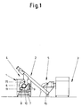
- the separating machine consists essentially of a basic machine 1, in which products of soft consistency, here meat, are separated from products of harder consistency, here tendons and cartilage, a feed device 2, which has a screw conveyor, and one Meat grinder as preparatory machine 3, in which the meat is pre-shredded.
- a transfer area 4 and 5 is arranged between the feed device 2 and the basic machine 1 and the preparatory machine 3 and the feed device 2.
- the basic machine 1 and the transfer areas 4 and 5 are shown in FIG. 1 open to the viewer.
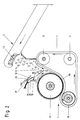
- the basic machine 1 known per se consists essentially of a drum 6 and an elastic layer 7 in the form of an endless rubber band which is guided over a press roller 8 and two deflection rollers 9 and rests under pressure in a region 10 on the drum 6.
- the drum 6, the press roller 8 and the deflection rollers 9 are rotatably mounted between two side walls 11, of which only the rear one is shown in FIG. 1.
- the drum 6 and the press roller 8 are driven at the same peripheral speed in the opposite direction of rotation by a drive arranged behind the side wall 11.
- the drum 6 and the elastic layer 7 on the side opposite to the direction of movement form an approximately triangular-shaped intermediate space 12 into which the pieces of meat 14 conveyed by the screw conveyor 13 of the feed device 2 enter.
- a transmitter-receiver device 15 is directed into the intermediate space 12.
- the transmitter-receiver device 15 has a GaAs diode as the transmitter and an Si photodiode as the receiver.
- the GaAs diode emits modulated infrared light.
- the measuring beams of the two diodes are aligned in such a way that the Si photodiode registers only the infrared light reflected within a certain measuring distance A in front of the transmitter-receiver device.
- the measuring distance A extends deep into the intermediate space, for example approximately up to the middle of the intermediate space 12, in order to remove any pieces of meat 14 present there to prove and to exclude external reflections on the drum 6 and on the band 7.
- the GaAs diode 16 and the Si photodiode 17 are connected to the drive of the drum 6 and the drive of the feed device 2 via a control device (not shown in the drawing).
- the control device comprises an amplifier and evaluation stage with drop-off and on-delayed tent relays which emit signals to the drive motors.
- the delay in the activation of the time relays is about 10 seconds from the shredded pieces of meat 14 and, in a known manner, ensures that the drive motor of the drum 6 is switched off if the Si photodiode 17 has not received a signal within this time, and that the drive motor of the feeder 2 is issued when the Si photodiode has continuously received signals during this time.
- the drive motor of the drum 6 can be switched on again as soon as the Si photodiode has received a signal, and the drive motor of the feed device 2 can be switched on again if the Si photodiode does not switch after a predetermined time Received signal.
- control device can have an electrical speed adjuster or a mechanical adjusting device with which the drive motor of the drum 6 and the drive motor of the feed device 2 can be continuously regulated in a known manner as a function of the frequency of the signals registered by the Si photodiode.
- the GaAs diode and the Si photodiode are arranged together in a cylindrical housing 18. They are commercially available as such a measuring unit.
- the transceiver device 15 is inserted into a cylindrical sleeve 19 which engages through an opening 20 arranged above the drum 6 in the wall 21 of the transfer area between the feed device 2 and the intermediate space 12.
- the sleeve 19 is welded in its outer edge region in the opening 20 of the wall 21. According to the construction of the basic machine 1, the cylindrical sleeve 19 is inclined downwards relative to the horizontal, so that the transmitter-receiver device 15 is directed into the area to be monitored.
- deflector plate 22 which extends over it and is more inclined downward.
- the deflector plate 22 is welded to the wall 21 with its end facing outward.
- a transmitter-receiver device 15 is also arranged for monitoring the transfer area 5 between the preparatory machine 3 and the feed device 2.
- the transceiver device 15 used in this area is of the same type as the transceiver device described above.
- the GaAs diode and Si photodiode arranged in a cylindrical housing 18 are arranged so that the measuring beam registers the pieces of meat 14 falling from the outlet connection 23 of the meat grinder into the screw conveyor 13.
- the measuring distance A extends approximately to the middle of the fall area of the pieces of meat 14.
- the transmitter-receiver device 15 is inserted from the outside into a sleeve 19 which is welded into an opening 24 in the wall 25 of the transfer area. Above the sleeve 19 there is a deflector plate 22 which extends over this and is welded to the wall 25 at its outwardly facing end.
- the transmitter-receiver device 15 shown in FIG. 3 is connected to the drive of the meat grinder and the drive of the feed device 2 via a control device (not shown in the drawing).
- the circuit corresponds to the function described above in connection with the control device for driving the drum 6 and driving the feed device 2.
- the control device can also cause the drive motors to be automatically restarted as above.
Landscapes
- Engineering & Computer Science (AREA)
- Life Sciences & Earth Sciences (AREA)
- Mechanical Engineering (AREA)
- Wood Science & Technology (AREA)
- Zoology (AREA)
- Food Science & Technology (AREA)
- Meat, Egg Or Seafood Products (AREA)
- Sheets, Magazines, And Separation Thereof (AREA)
- Crushing And Pulverization Processes (AREA)
- Control Of Conveyors (AREA)
Description
Die Erfindung betrifft eine Trennmaschine zur Trennung von Produkten weicher und härterer Konsistenz, mit einer zylinderförmigen Trommel, die in ihrer Umfangswand Öffnungen zum Hindurchtreten des oder der Produkte weicher Konsistenz aufweist und die um ihre Achse über eine Heuervorrichtung drehbar antreibbar ist, mit einer seitlich und/oder unterhalb der Trommel angeordneten und unter Druck gegen die Trommel anliegenden elastischen Schicht, die simultan und in dem Bereich, in dem die Schicht an der Trommel anliegt, in gleicher Richtung mit dieser bewegbar ist und die mit der Trommel an der der Bewegungsrichtung entgegengesetzten Seite einen im Schnitt annähernd dreiecksförmigen Zwischenraum bildet, und mit einer Zuführungsvorrichtung zur Zuführung der Produkte in den Zwischenraum.The invention relates to a separating machine for separating products of softer and harder consistency, with a cylindrical drum which has openings in its peripheral wall for the passage of the product or products of soft consistency and which can be driven rotatably about its axis via a hay device, with a laterally and / or arranged below the drum and under pressure against the drum resilient layer which can be moved simultaneously and in the area in which the layer lies against the drum in the same direction with the drum and which is one with the drum on the opposite side of the direction of movement forms an approximately triangular gap on average, and with a feed device for feeding the products into the gap.
Derartige Maschinen werden in der Lebensmittel verarbeitenden Industrie, z.B. als Fleischentsehnungsmaschine, verwendet. Dabei wird das zu entsehnende Fleisch über die Zuführungsvorrichtung dem Zwischenraum zwischen Trommel und elastischer Schicht zugeführt. Aufgrund der Bewegung der Trommel und der elastischen Schicht wird das Fleisch in den Bereich, in dem die elastische Schicht gegen die Trommel gedrückt ist, hineingezogen und einem immer stärker werdenden Druck ausgesetzt. Dabei werden die weichen Teile des Fleisches durch die Öffnungen in der Umfangswand der Trommel hindurch ins Innere der Trommel gedrückt, während die härteren Bestandteile des Fleisches, Sehnen und Knorpel , an der äußeren Umfangsfläche der Trommel verbleiben. Die weichen, sehnen- und knorpelfreien Fleischstücke können dann mittels einer innerhalb der Trommel fest angebrachten Förderschnecke aus dieser heraus in einen Entnahmebehälter befördert werden. Davon getrennt können andererseits Sehnen und Knorpel durch einen gegen die Umfangsfläche der Trommel laufenden Abstreifer von dieser entfernt und über ein Sehnen-Transportband in einen zweiten Entnahmebehälter gegeben werden.Such machines are used in the food processing industry, for example as a meat extracting machine. The meat to be extracted is fed to the space between the drum and the elastic layer via the feed device. Due to the movement of the drum and the elastic layer, the meat is drawn into the area in which the elastic layer is pressed against the drum and subjected to an ever increasing pressure. The soft parts of the meat are covered by the Openings in the peripheral wall of the drum are pushed inside the drum, while the harder components of the meat, tendons and cartilage, remain on the outer peripheral surface of the drum. The soft, tendon-free and cartilage-free pieces of meat can then be conveyed out of the drum into a removal container by means of a screw conveyor fixedly attached inside the drum. Separated from this, on the other hand, tendons and cartilage can be removed from the drum by a scraper running against the circumferential surface and placed in a second removal container via a tendon conveyor belt.
Zum Zwecke der Fleischentsehnung besteht die Trommel aus korrosionsfreiem Edelstahl und hat je nach Rohware und Endprodukt Bohrungen zwischen 1 und 10 mm Durchmesser. Die elastische Schicht ist bei der bekannten Maschine in Form eines hochelastischen Gummibandes ausgebildet, das über eine Preßrolle und weitere Umlenkrollen an die Trommel gedrückt wird.For the purpose of meat extraction, the drum is made of corrosion-free stainless steel and, depending on the raw material and end product, has holes between 1 and 10 mm in diameter. The elastic layer is formed in the known machine in the form of a highly elastic rubber band which is pressed against the drum via a press roller and further deflection rollers.
Beim Betrieb einer solchen Maschine muß darauf geachtet werden, daß die Maschine nicht ohne Produkteingabe läuft. Der Trockenlauf der Maschine führt zum Verschleiß des sehr kostbaren hochelastischen Gummibandes und sollte auch aus wirtschaftlichen Gesichtspunkten (Totzeiten und unnötiger Energieverbrauch) vermieden werden.When operating such a machine, care must be taken that the machine does not run without product input. The dry running of the machine leads to the wear of the very valuable, highly elastic rubber band and should also be avoided from an economic point of view (dead times and unnecessary energy consumption).
Andererseits muß auch die im Übergabebereich zwischen Zuführungseinrichtung und Trommel vorhandene Produktmenge überwacht werden, um eine Überfüllung dieses Bereichs zu vermeiden. Eine Überfüllung kann insbesondere bei Fleischprodukten, die zu einer Brückenbildung im Zwischenraum zwischen elastischer Schicht und Trommel neigen, zu einer Verstopfung der Maschine führen. Jede Verstopfung macht eine zeitraubende Reinigung erforderlich und bewirkt eine Unterbrechung des Arbeitsflusses mit teueren Stillstandszeiten.On the other hand, the amount of product present in the transfer area between the feed device and drum must also be monitored in order to avoid an overfilling of this area. Overfilling can clog the machine, particularly in meat products that tend to bridge the gap between the elastic layer and the drum. Every blockage requires time-consuming cleaning and causes an interruption of the work flow with expensive downtimes.
Die erforderliche Überwachung der Maschine wurde bisher hauptsächlich durch die Bedienungsperson vorgenommen. Dies setzt eine ständige Kontrolle der Produktzufuhr und der Produktmenge in dem Übergabebereich zwischen Zulieferungsvorrichtung und Trommel voraus. Bei unterbrochener Produktzufuhr oder zu starker Anfüllung des Übergabebereichs mußte der Antrieb der Maschine bzw. der Zuführungsvorrichtung manuell abgestellt werden. Dabei kam es häufig zu Verzögerungen mit den oben beschriebenen Nachteilen.The necessary monitoring of the machine has so far been carried out mainly by the operator. This requires constant control of the product supply and the quantity of product in the transfer area between the delivery device and the drum. If the product supply was interrupted or the transfer area was overfilled, the drive of the machine or the feed device had to be switched off manually. This often resulted in delays with the disadvantages described above.
Zwar wurden schon mechanische Überwachungssysteme verwendet z.B wie in DE-B-25 48 980 veröffentlicht , und gemäß Oberbegriff des ersten Anspruchs. Diese haben jedoch den Nachteil, daß die zu verarbeitenden Produkte sich leicht an den mechanischen Teilen festsetzen und sie an ihrer Bewegung hindern. Aufgrund des dadurch bewirkten häufigen Ausfalls und der erforderlichen Reinigung haben sich mechanische Überwachungssysteme in der Praxis als wenig brauchbar erwiesen.Mechanical monitoring systems have already been used, for example, as published in DE-B-25 48 980, and in accordance with the preamble of the first claim. However, these have the disadvantage that the products to be processed easily stick to the mechanical parts and prevent them from moving. Due to the frequent breakdown caused by this and the necessary cleaning, mechanical monitoring systems have proven to be of little use in practice.
Der Erfindung liegt die Aufgabe zugrunde, eine Trennmaschine der obigen Art zu schaffen, bei der unnötiger Verschleiß der elastischen Schicht durch Trockenlauf der Maschine vermieden, die Maschine optimal ausgelastet und einer Überfüllung und Verstopfung vorgebeugt wird.The invention has for its object to provide a cutting machine of the above type, in which unnecessary wear of the elastic layer is avoided by running the machine dry, the machine is optimally utilized and overfilling and clogging is prevented.
Die Aufgabe wird gemäß Patentanspruch 1 dadurch gelöst, daß eine Sender-Empfänger-Vorrichtung vorgesehen ist, wobei durch den Sender elektromagnetische oder akkustische Signale emittierbar und durch den Empfänger entweder unreflektierte Signale oder innerhalb eines bestimmten Meßabstands vom Sender reflektierte Signale registrierbar sind, der Sender und Empfänger außerhalb des Bereichs angeordnet sind, der den Zwischenraum zwischen Trommel und elastischer Schicht und dem Raum umfaßt, durch den die Produkte von der Zuführungsvorrichtung dem Zwischenraum zuführbar sind, und der Sender und Empfänger auf diesen Bereich gerichtet sind, und die Sender-Empfänger-Vorrichtung über die Steuervorrichtung mit dem Antrieb der Trommel und dem Antrieb der Zuführungsvorrichtung zusammengeschaltet ist, wobei in dem Fall, daß der Empfänger unreflektierte Signale registriert, durch die Schaltung der Antrieb der Trommel ausstellbar ist, wenn der Empfänger während einer vorgegebenen Zeit durchgehend Signale empfangen hat, und der Antrieb der Zuführungsvorrichtung ausstellbar ist, wenn der Empfänger nach einer vorgegebenen Zeit keine Signale empfangen hat, und wobei in dem Fall, daß der Empfänger reflektierte Signale registriert, durch die Schaltung der Antrieb der Trommel ausstellbar ist, wenn der Empfänger nach einer vorgegebenen Zeit kein Signal empfangen hat, und der Antrieb der Zuführungsvorrichtung ausstellbar ist, wenn der Empfänger während einer vorgegebenen Zeit durchgehend Signale empfangen hat.The object is achieved according to claim 1 in that a transmitter-receiver device is provided, wherein electromagnetic or acoustic signals can be emitted by the transmitter and either unreflected signals or signals reflected by the transmitter can be registered by the receiver, the transmitter and Receiver outside of the Are arranged area which comprises the space between the drum and the elastic layer and the space through which the products can be fed from the feed device to the space, and the transmitter and receiver are directed to this area, and the transceiver device via the control device is interconnected with the drive of the drum and the drive of the feed device, wherein in the event that the receiver registers unreflected signals, the circuit can be used to switch the drive of the drum if the receiver has continuously received signals for a predetermined time, and the drive of the feed device can be switched off if the receiver has not received any signals after a predetermined time and, in the event that the receiver registers reflected signals, the circuit can be used to switch the drum drive if the receiver has not received any signal after a predetermined time Has, and the drive of the feed device can be switched off if the receiver has continuously received signals for a predetermined time.
Aufgrund der erfindungsgemäßen Konstruktion wird die Maschine automatisch abgestellt, wenn innerhalb einer vorbestimmten Zeit, die z.B. 10 sec. betragen kann, kein Produkt nachfließt. Die Zeitspanne wird so gewählt, daß ein Verschleiß der elastischen Schicht noch nicht zu befürchten ist, aber kurzzeitige Unterbrechungen der Produktzufuhr noch nicht zum Abstellen und Takten der Maschine führen. Andererseits wird die Zuführungsvorrichtung ausgestellt, wenn die Produktmenge in den Übergabebereich zwischen der Zuführungsvorrichtung und der Trommel über eine vorgegebene Zeit hinweg ein bestimmtes Volumen überschreitet und daher die Gefahr einer Verstopfung der Maschine besteht.Due to the construction according to the invention, the machine is switched off automatically if no product continues to flow within a predetermined time, which can be, for example, 10 seconds. The time period is chosen so that wear of the elastic layer is not yet to be feared, but brief interruptions in the product supply do not yet lead to the machine being switched off and clocked. On the other hand, the feeder is turned off when the amount of product in the transfer area between the feeder and the drum exceeds a certain volume for a predetermined time, and there is therefore a danger of the machine being clogged.
Wenn das Produkt wieder nachfließt bzw. das im Übergabebereich zwischen Zuführungsvorrichtung und Trommel gestaute Produkt verarbeitet ist, so kann durch die Steuervorrichtung auch ein automatisches Anstellen der Trommel und der Zuführungsvorrichtung vorgesehen sein. Dazu ist in dem Fall, daß der Empfänger unreflektierte Signale registriert, durch die Schaltung der Antrieb der Trommel wieder anstellbar, wenn der Empfänger nach einer vorgegebenen Zeit kein Signal empfangen hat, und der Antrieb der Zuführungsrichtung wieder anstellbar, wenn der Empfänger während einer vorgegebenen Zeit durchgehend Signale empfangen hat, und in dem Fall, daß der Empfänger reflektierte Strahlen registriert, durch die Schaltung der Antrieb der Trommel wieder anstellbar, sobald der Empfänger ein Signal empfangen hat, und der Antrieb der Zuführungsvorrichtung wieder anstellbar, wenn der Empfänger nach einer vorgegebenen Zeit kein Signal empfangen hat.If the product flows again or the product jammed in the transfer area between the feed device and drum has been processed, then the control device can also provide for the drum and the feed device to be turned on automatically. In addition, in the event that the receiver registers unreflected signals, the drive of the drum can be switched on again if the receiver has not received a signal after a predetermined time, and the drive of the feed direction can be switched on again if the receiver during a predetermined time has continuously received signals, and in the event that the receiver registers reflected rays, by switching the drum the drum can be turned on again as soon as the receiver has received a signal and the drive of the feeder can be turned on again when the receiver after a predetermined time received no signal.
Zweckmäßigerweise sind Sender und Empfänger tief in dem zu überwachenden Bereich hineingerichtet, um Staubildungen möglichst im Anfangsstadium registrieren und durch Zurücknahme der Zulieferung verhindern zu können. Daher sind bei einer Sender-Empfänger-Vorrichtung, deren Empfänger reflektierte Signale registriert, Sender und Empfänger vorzugsweise in den Zwischenraum zwischen Trommel und elastischer Schicht gerichtet. Der vorbestimmte Meßabstand sollte dann etwa bis zur Mitte des Zwischenraums reichen, um Hintergrundreflektionen durch die Trommel oder die elastische Schicht zu vermeiden.The transmitter and receiver are expediently set deep in the area to be monitored in order to register congestion as early as possible and to be able to prevent it by taking back the delivery. Therefore, in a transmitter-receiver device whose receiver registers reflected signals, the transmitter and receiver are preferably directed into the space between the drum and the elastic layer. The predetermined measuring distance should then extend approximately to the middle of the space in order to avoid background reflections from the drum or the elastic layer.
Die Steuerung kann zur Ein-Aus-Schaltung der Antriebe abfallsverzögerte bzw. anzugsverzögerte Zeitrelais aufweisen.The controller can have drop-delay or pick-up delayed time relays for switching the drives on and off.
Um die Verarbeitungsgeschwindigkeit an die Produktzufuhr und umgekehrt noch besser anzupassen und damit eine optimale Auslastung der Maschine zu erreichen, kann mit der Steuervorrichtung der Antrieb der Trommel und/oder der Antrieb der Zuführungsvorrichtung in Abhängigkeit von der Frequenz der vom Empfänger registrierten Signale über einen elektrischen Drehzahlversteller oder eine mechanische Verstelleinrichtung stetig regelbar sein.At the processing speed to the product feed and vice versa to adapt even better and thus achieve an optimal utilization of the machine, the control of the drive of the drum and / or the drive of the feed device can be continuously regulated depending on the frequency of the signals registered by the receiver via an electrical speed adjuster or a mechanical adjusting device be.
Vorzugsweise weist die Sender-Empfänger-Vorrichtung einen Infrarot-Sender und -Empfänger auf. Infrarot-Sender und -Empfänger sind in feuchter Umgebung, wie sie bei der Lebensmittelverarbeitung meistens vorhanden ist, besonders geeignet.The transceiver device preferably has an infrared transmitter and receiver. Infrared transmitters and receivers are particularly suitable in a humid environment, such as is usually found in food processing.
Das vom Sender emittierte Infrarotlicht ist vorzugsweise moduliert, um es von störendem Fremdlicht zu unterscheiden.The infrared light emitted by the transmitter is preferably modulated in order to distinguish it from interfering external light.
Die Sender-Empfänger-Vorrichtung weist vorzugsweise als Sender eine GaAs-Diode und als Empfänger eine Si-Photodiode auf.The transmitter-receiver device preferably has a GaAs diode as a transmitter and a Si photodiode as a receiver.
In einer Sender-Empfänger-Vorrichtung, wobei der Empfänger in einem bestimmten Meßabstand vom Sender reflektierte Signale registriert, sind die GaAs-Diode und die Si-Photodiode zweckmäßigerweise gemeinsam in einem zylindrischen Gehäuse angeordnet und die geometrischen Strahlengänge der beiden Dioden so gegeneinander ausgerichtet, daß sie sich in dem vorgegebenen Meßabstand vor der Sender-Empfänger-Vorrichtung schneiden. Das zylindrische Gehäuse bietet Schutz vor Verschmutzung und ermöglicht den Einbau der Sender-Empfänger-Vorrichtung als vorgefertigte, kompakte Einheit. Derartige Vorrichtungen sind im Handel erhältlich.In a transmitter-receiver device, the receiver registering signals reflected from the transmitter at a certain measuring distance, the GaAs diode and the Si photodiode are expediently arranged together in a cylindrical housing and the geometric beam paths of the two diodes are aligned with one another such that they intersect at the specified measuring distance in front of the transmitter-receiver device. The cylindrical housing offers protection against dirt and enables the transmitter-receiver device to be installed as a prefabricated, compact unit. Such devices are commercially available.
Die als eine solche Einheit ausgebildete Sender-Empfänger-Vorrichtung wird bevorzugt in eine zylindrische Hülse eingesetzt, die von außen in den Raum reicht, durch den die Produkte von der Zuführungsvorrichtung dem Zwischenraum zwischen Trommel und elastischer Schicht zuführbar sind. Die zylindrische Hülse kann gegen die Horizontale nach unten geneigt sein, um entsprechend der Konstruktion der Maschine ein Hineinreichen des Meßstrahls in den zu überwachenden Bereich zu ermöglichen und die Stirnseite der Sender-Empfänger-Vorrichtung vor Verschmutzung zu schützen.The transmitter-receiver device designed as such a unit is preferably inserted into a cylindrical sleeve which extends from the outside into the space through which the products can be fed from the feed device to the space between the drum and the elastic layer. The cylindrical sleeve can be inclined downwards relative to the horizontal, in order to allow the measuring beam to reach into the area to be monitored in accordance with the design of the machine and to protect the end face of the transmitter-receiver device from contamination.
Um die Verschmutzungsgefahr der Sender-Empfänger-Vorrichtung noch weiter zu eliminieren, kann über der Hülse eine über diese reichende Abweiserplatte angeordnet sein.In order to further eliminate the risk of contamination of the transmitter-receiver device, a deflector plate extending over this can be arranged over the sleeve.
Wenn der Zuführungsvorrichtung eine vorbereitende Maschine vorgeschaltet ist und zwischen vorbereitender Maschine und Zuführungsvorrichtung ein Übergabebereich für die vorbereiteten Produkte angeordnet ist, werden die erfindungsgemäße Sender-Empfänger-Vorrichtung und Steuervorrichtung bevorzugt auch zur Überwachung dieses Übergabebereichs eingesetzt. Dazu werden Sender und Empfänger außerhalb des Übergabebereichs angeordnet und auf diesen gerichtet und eine Steuervorrichtung verwendet, mit der die Sender-Empfänger-Vorrichtung mit dem Antrieb der Zuführungsvorrichtung und dem Antrieb der vorbereitenden Maschine zusammengeschaltet ist, wobei in dem Fall, daß der Empfänger unreflektierte Signale registriert, durch die Schaltung der Antrieb der Zuführungsvorrichtung ausstellbar ist, wenn der Empfänger während einer vorgegebenen Zeit durchgehend Signale empfangen hat, und der Antrieb der vorbereitenden Maschine ausstellbar ist, wenn der Empfänger nach einer vorgegebenen Zeit keine Signale empfangen hat, und wobei in dem Fall, daß der Empfänger reflektierte Signale registriert, durch die Schaltung der Antrieb der Zuführungsvorrichtung ausstellbar ist, wenn der Empfänger nach einer vorgegebenen Zeit kein Signal empfangen hat, und der Antrieb der vorbereitenden Maschine ausstellbar ist, wenn der Empfänger während einer vorgegebenen Zeit durchgehend Signale empfangen hat. Aufgrund dieser weiteren Ausbildung der Erfindung werden Totzeiten der Zuführungseinrichtung ausgeschaltet und ein Überfüllen vermieden.If the feed device is preceded by a preparatory machine and a transfer area for the prepared products is arranged between the preparatory machine and the feed device, the transmitter-receiver device and control device according to the invention are preferably also used to monitor this transfer area. For this purpose, the transmitter and the receiver are arranged outside the transfer area and are directed towards the latter, and a control device is used with which the transmitter-receiver device is interconnected with the drive of the feed device and the drive of the preparatory machine, in the event that the receiver receives unreflected signals registered, by means of the circuit the drive of the feed device can be switched off if the receiver has continuously received signals for a predetermined time, and the drive of the preparatory machine can be switched off if the receiver has not received any signals after a predetermined time, and in that case that the receiver registers reflected signals by switching the drive of the Feed device can be turned off when the receiver has not received a signal after a predetermined time, and the drive of the preparatory machine can be turned off when the receiver has continuously received signals during a predetermined time. Due to this further embodiment of the invention, dead times of the feed device are switched off and overfilling is avoided.
Desweiteren kann auch ein automatisches Wiederanstellen der Antriebe, wie oben in Bezug auf den Überwachungsbereich zwischen Grundmaschine und Zuführungsvorrichtung beschrieben, vorgesehen sein.Furthermore, automatic resetting of the drives, as described above in relation to the monitoring area between the basic machine and the feed device, can also be provided.
Im nachfolgenden wird die Erfindung beispielsweise anhand des in der Zeichnung dargestellten Ausführungsbeispiels verdeutlicht. Es zeigen:
- Fig. 1
- eine Seitenansicht einer Trennmaschine mit vorgeschalteter vorbereitender Maschine,
- Fig. 2
- eine vergrößerte Ansicht des Innern der in Fig. 1 dargestellten Maschine und
- Fig. 3
- eine vergrößerte Ansicht des Übergabebereichs zwischen vorbereitender Maschine und Zuführungsvorrichtung.
- Fig. 1
- a side view of a cutting machine with an upstream preparatory machine,
- Fig. 2
- an enlarged view of the inside of the machine shown in Fig. 1 and
- Fig. 3
- an enlarged view of the transfer area between the preparatory machine and the feed device.
Wie aus Fig. 1 hervorgeht, besteht die Trennmaschine im wesentlichen aus einer Grundmaschine 1, in der Produkte weicher Konsistenz, hier Fleisch, von Produkten härterer Konsistenz, hier Sehnen und Knorpel, getrennt werden, einer Zuführungsvorrichtung 2, die eine Förderschnecke aufweist, und einem Fleischwolf als vorbereitender Maschine 3, in der das Fleisch vorzerkleinert wird.As can be seen from Fig. 1, the separating machine consists essentially of a basic machine 1, in which products of soft consistency, here meat, are separated from products of harder consistency, here tendons and cartilage, a
Zwischen der Zuführungsvorrichtung 2 und der Grundma-schine 1 und der vorbereitenden Maschine 3 und der Zuführungsvorrichtung 2 ist jeweils ein Übergabebereich 4 bzw. 5 angeordnet. Die Grundmaschine 1 und die Übergabebereiche 4 und 5 sind in Fig. 1 zum Betrachter hin offen dargestellt.Between the
Die an sich bekannte Grundmaschine 1 besteht, wie in Fig. 1 angedeutet und in Fig. 2 näher dargestellt, im wesentlichen aus einer Trommel 6 und einer elastischen Schicht 7 in Form eines endlosen Gummibandes, das über eine Preßrolle 8 und zwei Umlenkrollen 9 geführt ist und in einem Bereich 10 an der Trommel 6 unter Druck anliegt. Die Trommel 6, die Preßrolle 8 und die Umlenkrollen 9 sind drehbar zwischen zwei Seitenwänden 11, von denen nur die hintere in Fig. 1 dargestellt ist, angebracht. Die Trommel 6 und die Preßrolle 8 werden mit gleicher Umfangsgeschwindigkeit in entgegengesetzter Drehrichtung durch einen hinter der Seitenwand 11 angeordneten Antrieb angetrieben.The basic machine 1 known per se, as indicated in FIG. 1 and shown in more detail in FIG. 2, consists essentially of a
Wie in Fig. 2 genauer gezeigt ist, bilden die Trommel 6 und die elastische Schicht 7 an der der Bewegungsrichtung entgegengesetzten Seite einen im Schnitt annähernd dreiecksförmigen Zwischenraum 12, in den die durch die Förderschnecke 13 der Zuführungsvorrichtung 2 beförderten Fleischstücke 14 gelangen.As shown in more detail in FIG. 2, the
In den Zwischenraum 12 hinein ist eine Sender-Empfänger-Vorrichtung 15 gerichtet. Die Sender-Empfänger-Vorrichtung 15 weist eine GaAs-Diode als Sender und eine Si-Photodiode als Empfänger auf. Die GaAs-Diode emittiert moduliertes Infrarotlicht. Die Meßstrahlen der beiden Dioden sind so ausgerichtet, daß die Si-Photodiode nur das innerhalb eines bestimmten Meßabstands A vor der Sender-Empfänger-Vorrichtung reflektierte Infrarotlicht registriert. Der Meßabstand A reicht tief in den Zwischenraum, z.B. etwa bis zur Mitte des Zwischenraums 12 hinein, um dort eventuell vorhandene Fleischstücke 14 nachzuweisen und Fremdreflektionen an der Trommel 6 und am Band 7 auszuschließen.A transmitter-
Die GaAs-Diode 16 und die Si-Photodiode 17 sind über eine in der Zeichnung nicht dargestellte Steuervorrichtung mit dem Antrieb der Trommel 6 und dem Antrieb der Zuführungsvorrichtung 2 zusammengeschaltet. Die Steuervorrichtung umfaßt eine Verstärker- und Auswertungsstufe mit abfalls- und anzugsverzögerten Zeltrelais, die Signale an die Antriebsmotoren abgeben. Die Abfalls-bzw. Anzugsverzögerung der Zeitrelais beträgt im vorliegenden Fall der Entsehnung vorzerkleinerter Fleischstücke 14 etwa 10 sec. und sorgt in bekannter Weise dafür, daß der Antriebsmotor der Trommel 6 ausgestellt wird, wenn die Si-Photodiode 17 innerhalb dieser Zeit kein Signal empfangen hat, und daß der Antriebsmotor der Zuführungsvorrichtung 2 ausgestellt wird, wenn die Si-Photodiode während dieser Zeit durchgehend Signale empfangen hat.The
In einer Erweiterung der hier betrachteten einfachsten Ausführungsform der Steuervorrichtung kann der Antriebsmotor der Trommel 6 wieder angestellt werden, sobald die Si-Photodiode ein Signal empfangen hat, und der Antriebsmotor der Zuführungsvorrichtung 2 wieder angestellt werden, wenn die Si-Photodiode nach einer vorgegebenen Zeit kein Signal empfangen hat.In an extension of the simplest embodiment of the control device considered here, the drive motor of the
Darüber hinaus kann die Steuervorrichtung einen elektrischen Drehzahlversteller oder eine mechanische Verstelleinrichtung aufweisen, mit denen der Antriebsmotor der Trommel 6 und der Antriebsmotor der Zuführungsvorrichtung 2 in Abhängigkeit von der Frequenz der von der Si-Photodiode registrierten Signale in bekannter Weise stetig regelbar sind.In addition, the control device can have an electrical speed adjuster or a mechanical adjusting device with which the drive motor of the
Die GaAs-Diode und die Si-Photodiode sind gemeinsam in einem zylindrischen Gehäuse 18 angeordnet. Als eine derartige Meßeinheit sind sie im Handel erhältlich.The GaAs diode and the Si photodiode are arranged together in a
Die Sender-Empfänger-Vorrichtung 15 ist in eine zylindrische Hülse 19 eingesetzt, die durch eine über der Trommel 6 angeordnete Öffnung 20 in der Wand 21 des Übergabebereiches zwischen der Zuführungsvorrichtung 2 und dem Zwischenraum 12 greift. Die Hülse 19 ist in ihrem äußeren Randbereich in der Öffnung 20 der Wand 21 festgeschweißt. Entsprechend der Konstruktion der Grundmaschine 1 ist die zylindrische Hülse 19 gegen die Horizontale nach unten geneigt, so daß die Sender-Empfänger-Vorrichtung 15 in den zu überwachenden Bereich hineingerichtet ist.The
Über der Hülse 19 ist eine über diese reichende und stärker nach unten geneigte Abweiserplatte 22 angeordnet. Die Abweiserplatte 22 ist mit ihrem nach außen weisenden Ende an der Wand 21 festgeschweißt.Above the
Wie aus Fig. 1 und genauer aus Fig. 3 hervorgeht, ist zur Überwachung des Übergabebereichs 5 zwischen der vorbereitenden Maschine 3 und der Zuführungsvorrichtung 2 ebenfalls eine Sender-Empfänger-Vorrichtung 15 angeordnet. Die in diesem Bereich verwendete Sender-Empfänger-Vorrichtung 15 ist von gleicher Bauart wie die oben beschriebene Sender-Empfänger-Vorrichtung.As can be seen from FIG. 1 and more precisely from FIG. 3, a transmitter-
Die in einem zylindrischen Gehäuse 18 angeordnete GaAs-Diode und Si-Photodiode sind so angeordnet, daß der Meßstrahl die aus dem Austrittsstutzen 23 des Fleischwolfs in die Förderschnecke 13 fallenden Fleischstücke 14 registriert. Der Meßabstand A reicht etwa bis in die Mitte des Fallbereichs der Fleischstücke 14.The GaAs diode and Si photodiode arranged in a
Die Sender-Empfänger-Vorrichtung 15 ist von außen in eine Hülse 19 eingesetzt, die in einer Öffnung 24 in der Wand 25 des Übergabebereichs festgeschweißt ist. Über der Hülse 19 ist eine über diese reichende Abweiserplatte 22 angeordnet, die an ihrem nach außen weisenden Ende an der Wand 25 festgeschweißt ist.The transmitter-
Die In Fig. 3 gezeigte Sender-Empfänger-Vorrichtung 15 ist über eine in der Zeichnung nicht dargestellte Steuervorrichtung mit dem Antrieb des Fleischwolfs und dem Antrieb der Zuführungsvorrichtung 2 zusammengeschaltet. Die Schaltung entspricht der oben im Zusammenhang mit der Steuervorrichtung für den Antrieb der Trommel 6 und dem Antrieb der Zuführungsvorrichtung 2 beschriebenen Funktion. Mit Hilfe von abfallsverzögerten bzw. anzugsverzögerten Zeitrelais wird in an sich bekannter Weise dafür gesorgt, daß der Antriebsmotor des Fleischwolfs ausgestellt wird, wenn die Si-Photodiode während einer vorgegebenen Zeit durchgehend Signale empfangen hat, und daß der Antriebsmotor der Zuführungsvorrichtung 2 ausgestellt wird, wenn die Si-Photodiode 17 innerhalb einer vorgegebenen Zeit kein Signal empfangen hat.The transmitter-
Die Steuervorrichtung kann ebenfalls wie oben ein automatisches Wiederanstellen der Antriebsmotoren bewirken.The control device can also cause the drive motors to be automatically restarted as above.
Claims (12)
- Separating apparatus for the separation of products of soft and hard consistencies, comprising a cylindrical drum which is provided, in its peripheral wall, with apertures for the product or products of soft consistency to pass through and which can be driven, by means of a control device, in a rotatable manner about its axis, and which comprises a resilient layer which is disposed laterally of and/or below the drum and which abuts the drum under pressure, which layer is moveable in the same direction as the drum, simultaneously and in the area in which it abuts the drum, and which forms, together with the drum, on the side opposite to the direction of movement, a space which is virtually triangular in section, and comprising a supply device for supplying the products into the space, characterised by a transceiver device (15), wherein electromagnetic or acoustic signals can be transmitted by the transmitter and signals that either are not reflected or are reflected by the transmitter within a predetermined measuring distance (A) can be registered by the receiver, the transmitter and the receiver being disposed outside the area which surrounds the space (12) between the drum (6) and the resilient layer (7) and the chamber through which the products can be supplied to the space (12) from the supply device (2), the transmitter and the receiver being directed towards this area, and the transceiver device (15) being connected to the drive of the drum (6) and the drive of the supply device (2) via the control device, wherein, in the case that the receiver registers signals that are not reflected, the drive of the drum (6) can be switched off by means of the circuit if the receiver has received signals continuously throughout a predetermined time, and the drive of the supply device (2) can be switched off if the receiver has not received a signal after a predetermined time and wherein, in the case that the receiver registers reflected signals, the drive of the drum (6) can be switched off by means of the circuit if the receiver has not received a signal after a predetermined time, and the drive of the supply device (2) can be switched off if the receiver has received signals continuously throughout a predetermined time.
- Separating apparatus according to Claim 1, characterised in that in the case that the receiver registers signals that are not reflected, the drive of the drum (6) can be switched back on by means of the circuit if the receiver has not received a signal after a predetermined time, and the drive (2) can be switched back on if the receiver has received signals continuously throughout a predetermined time, and in that in the case that the receiver registers reflected signals, the drive of the drum (6) can be switched back on as soon as the receiver has received a signal, and the drive of the supply device (2) can be switched back on if the receiver has not received a signal after a predetermined time.
- Separating apparatus according to Claim 1 or Claim 2, wherein the receiver registers, within a predetermined measuring distance (A), signals reflected by the transmitter, characterised in that the transmitter and the receiver are directed into the space (12) between the drum (6) and the resilient layer (7) and the predetermined measuring distance (A) extends approximately to the middle of the space (12).
- Separating apparatus according to any one of Claims 1 to 3, characterised in that the control device comprises a delayed drop out or delayed-pull time-lag relay for switching the drives on and off.
- Separating device according to one of Claims 1 to 4 characterised in that, by means of the control device, the drive of the drum (6) and/or the drive of the supply device (2) can be constantly regulated, via an electric rotational speed adjuster or a mechanical adjustment device, in dependence on the frequency of the signals registered by the receiver.
- Separating apparatus according to any one of Claims 1 to 5, characterised in that the transceiver device (15) comprises an infra-red transmitter and receiver.
- Separating apparatus according to Claim 6, characterised in that the infra-red light transmitted by the transmitter is modulated.
- Separating device according to Claim 6 or Claim 7, characterised in that the transceiver device (15) comprises a GaAs-diode (16) as a transmitter and an Si-photodiode (17) as a receiver.
- Separating apparatus according to Claim 8, wherein the receiver registers, within a predetermined measuring distance (A), signals reflected by the transmitter, characterized in that the GaAs-diode (16) and the Si-photodiode (17) are arranged together in a cylindrical casing (18) and the geometric ray length of the two diodes (16,17) intersect with one another in the predetermined measuring distance (A) of the GaAs-diode (16).
- Separating apparatus according to Claim 9, characterized in that the transceiver device is inserted in a cylindrical sleeve (19), which extends from the exterior into the chamber through which the products can be fed from the supply device (2) to the space (12) between the drum and the resilient layer (7), and in that the cylindrical sleeve (19) is inclined downwards in relation to the horizontal.
- Separating apparatus according to Claim 10, characterized in that a deflector plate (22) extending over the sleeve (19) is disposed above the latter.
- Separating apparatus according to one of Claims 1 to 11, wherein a preparing apparatus (3) is connected upstream of the supply device (2) and a transfer area (5) for the prepared products is disposed between the preparing apparatus (3) and the supply device (2), characterized by a transceiver device (15) and a control device according to any one of claims 1 to 11, wherein the transmitter and the receiver are disposed externally of the transfer area (5) and directed onto this latter and wherein, in the case that the receiver registers signals that are not reflected, the drive of the supply device (2) can be switched off by means of the control device if the receiver has received signals continuously throughout a predetermined time, and the drive of the preparing apparatus (3) can be switched off if the receiver has not received a signal after a predetermined time, and in the case of the receiver registering reflected signals, the drive of the supply device (2) can be switched off by means of the control device if the receiver has not received a signal after a predetermined time, and the drive of the preparing apparatus (3) can be switched off if the receiver has received signals continuously throughout a predetermined time.
Applications Claiming Priority (2)
| Application Number | Priority Date | Filing Date | Title |
|---|---|---|---|
| DE3844301 | 1988-12-30 | ||
| DE3844301A DE3844301C2 (en) | 1988-12-30 | 1988-12-30 | Cutting machine |
Publications (3)
| Publication Number | Publication Date |
|---|---|
| EP0375876A2 EP0375876A2 (en) | 1990-07-04 |
| EP0375876A3 EP0375876A3 (en) | 1992-03-18 |
| EP0375876B1 true EP0375876B1 (en) | 1994-07-20 |
Family
ID=6370511
Family Applications (1)
| Application Number | Title | Priority Date | Filing Date |
|---|---|---|---|
| EP89119896A Revoked EP0375876B1 (en) | 1988-12-30 | 1989-10-26 | Separating apparatus |
Country Status (2)
| Country | Link |
|---|---|
| EP (1) | EP0375876B1 (en) |
| DE (2) | DE3844301C2 (en) |
Cited By (1)
| Publication number | Priority date | Publication date | Assignee | Title |
|---|---|---|---|---|
| DE102018101985B3 (en) | 2018-01-30 | 2018-09-27 | Modernpack Hoppe Gmbh | Soft separator with fill state-dependent adaptation of the speed and method for operating such a soft separator |
Families Citing this family (6)
| Publication number | Priority date | Publication date | Assignee | Title |
|---|---|---|---|---|
| ATE112936T1 (en) * | 1990-11-28 | 1994-11-15 | Hohenester Hermann | METHOD AND DEVICE FOR PROCESSING MEAT. |
| DE4135529A1 (en) * | 1991-10-28 | 1993-04-29 | Hohenester Hermann | METHOD FOR PROCESSING AMOUNTS OF FOOD, IN PARTICULAR MEAT |
| DE4212927C2 (en) * | 1992-04-22 | 1995-10-19 | Modernpack Hoppe Gmbh | Cutting machine |
| DE29605004U1 (en) | 1996-03-18 | 1997-07-17 | Nordischer Maschinenbau | Separation device for separating the flowable and non-flowable components of products that are mixed together |
| DE19637640C2 (en) * | 1996-09-16 | 1999-12-16 | Nordischer Maschinenbau | Device for separating a mixture of substances |
| DE19846876A1 (en) * | 1998-10-13 | 2000-04-20 | Hermann Hohenester | Diced meat standardized for fat content using gravity selection and automated in-line parameters |
Family Cites Families (3)
| Publication number | Priority date | Publication date | Assignee | Title |
|---|---|---|---|---|
| NL6900308A (en) * | 1969-01-08 | 1970-07-10 | Meat separation | |
| US3612128A (en) * | 1969-12-11 | 1971-10-12 | Bibun Mach Const Co | Food-processing belt |
| JPS60237934A (en) * | 1984-05-12 | 1985-11-26 | 東洋水産機械株式会社 | Fish meat taking machine |
-
1988
- 1988-12-30 DE DE3844301A patent/DE3844301C2/en not_active Revoked
-
1989
- 1989-10-26 DE DE58908071T patent/DE58908071D1/en not_active Expired - Fee Related
- 1989-10-26 EP EP89119896A patent/EP0375876B1/en not_active Revoked
Cited By (4)
| Publication number | Priority date | Publication date | Assignee | Title |
|---|---|---|---|---|
| DE102018101985B3 (en) | 2018-01-30 | 2018-09-27 | Modernpack Hoppe Gmbh | Soft separator with fill state-dependent adaptation of the speed and method for operating such a soft separator |
| DE202018106192U1 (en) | 2018-01-30 | 2018-11-07 | Modernpack Hoppe Gmbh | Soft separator with fill state-dependent adjustment of the speed |
| WO2019149397A1 (en) | 2018-01-30 | 2019-08-08 | Modernpack Hoppe Gmbh | Soft material separator with fill-level-dependent adjustment of speed, and method for operating such a soft material separator |
| EP3713755B1 (en) | 2018-01-30 | 2022-05-04 | Modernpack Hoppe Gmbh | Soft material separator with fill-level-dependent adjustment of speed, and method for operating such a soft material separator |
Also Published As
| Publication number | Publication date |
|---|---|
| EP0375876A3 (en) | 1992-03-18 |
| EP0375876A2 (en) | 1990-07-04 |
| DE3844301A1 (en) | 1990-07-05 |
| DE58908071D1 (en) | 1994-08-25 |
| DE3844301C2 (en) | 1995-11-09 |
Similar Documents
| Publication | Publication Date | Title |
|---|---|---|
| DE2628706C2 (en) | ||
| EP0469380B1 (en) | Chopper | |
| DE4211657C1 (en) | ||
| EP0375876B1 (en) | Separating apparatus | |
| DE3140624A1 (en) | Dried material pulverizing and discharging device for multistage continuous vacuum drying apparatus | |
| DE2912218A1 (en) | Disintegrating machine for wood - has feed conveyor working together with counter-rotating deflector roller | |
| EP2058095A2 (en) | Chipping machine | |
| EP0365965B1 (en) | Installation for washing soil | |
| EP3199334A1 (en) | Rotary press for tablets | |
| DE3445429A1 (en) | Sorting installation for sorting dry industrial waste | |
| EP0395855B1 (en) | Method and device for distributing small parts like pieces of broken glass | |
| DE2157108A1 (en) | Device for washing and compressing disposable trays | |
| DE1901157B1 (en) | GRAIN SEPARATION DEVICE FOR A COMBINE | |
| DE19756670C2 (en) | Feed, support and storage device for shredding machines | |
| DE102004048275B3 (en) | Guide device to feed press mats to press for making chipboard has mat dropping device in form of turning table in transporting plane of both conveyors | |
| DE102018105763B4 (en) | Spreading device | |
| DE1507991C3 (en) | Device for separating meat from hard tissue | |
| EP0128135B1 (en) | Device for proportioning dough | |
| DE19713296A1 (en) | Round bale chopper | |
| DE2343958A1 (en) | Hop-picking machine with conveyor - incorporates chopper for bines directly after stripping machine and suction device for waste materials | |
| DE3019270A1 (en) | SCREW CONVEYOR | |
| DE1632433C (en) | Device for mixing powdery to granular substances with a liquid | |
| DE1532006B1 (en) | Shredding device for agricultural products, especially for meat, bread or the like. with vacuum system | |
| DE4113340A1 (en) | SCREW PRESS | |
| EP1327717B1 (en) | Spreading device for a winter service spreading vehicle |
Legal Events
| Date | Code | Title | Description |
|---|---|---|---|
| PUAI | Public reference made under article 153(3) epc to a published international application that has entered the european phase |
Free format text: ORIGINAL CODE: 0009012 |
|
| AK | Designated contracting states |
Kind code of ref document: A2 Designated state(s): DE GB NL |
|
| PUAL | Search report despatched |
Free format text: ORIGINAL CODE: 0009013 |
|
| AK | Designated contracting states |
Kind code of ref document: A3 Designated state(s): DE GB NL |
|
| 17P | Request for examination filed |
Effective date: 19920911 |
|
| 17Q | First examination report despatched |
Effective date: 19921214 |
|
| RAP3 | Party data changed (applicant data changed or rights of an application transferred) |
Owner name: MODERNPACK HOPPE GMBH |
|
| GRAA | (expected) grant |
Free format text: ORIGINAL CODE: 0009210 |
|
| AK | Designated contracting states |
Kind code of ref document: B1 Designated state(s): DE GB NL |
|
| REF | Corresponds to: |
Ref document number: 58908071 Country of ref document: DE Date of ref document: 19940825 |
|
| GBT | Gb: translation of ep patent filed (gb section 77(6)(a)/1977) |
Effective date: 19941005 |
|
| PLBI | Opposition filed |
Free format text: ORIGINAL CODE: 0009260 |
|
| 26 | Opposition filed |
Opponent name: NORDISCHER MASCHINENBAU RUD. BAADER GMBH & CO. KG Effective date: 19950412 |
|
| NLR1 | Nl: opposition has been filed with the epo |
Opponent name: NORDISCHER MASCHINENBAU RUD. BAADER GMBH & CO. KG |
|
| PLAB | Opposition data, opponent's data or that of the opponent's representative modified |
Free format text: ORIGINAL CODE: 0009299OPPO |
|
| PLBQ | Unpublished change to opponent data |
Free format text: ORIGINAL CODE: EPIDOS OPPO |
|
| R26 | Opposition filed (corrected) |
Opponent name: NORDISCHER MASCHINENBAU RUD. BAADER GMBH & CO. KG Effective date: 19950412 |
|
| NLR1 | Nl: opposition has been filed with the epo |
Opponent name: NORDISCHER MASCHINENBAU RUD. BAADER GMBH & CO. KG |
|
| RDAH | Patent revoked |
Free format text: ORIGINAL CODE: EPIDOS REVO |
|
| PGFP | Annual fee paid to national office [announced via postgrant information from national office to epo] |
Ref country code: GB Payment date: 19991006 Year of fee payment: 11 |
|
| PGFP | Annual fee paid to national office [announced via postgrant information from national office to epo] |
Ref country code: NL Payment date: 19991027 Year of fee payment: 11 |
|
| APAC | Appeal dossier modified |
Free format text: ORIGINAL CODE: EPIDOS NOAPO |
|
| APAE | Appeal reference modified |
Free format text: ORIGINAL CODE: EPIDOS REFNO |
|
| PGFP | Annual fee paid to national office [announced via postgrant information from national office to epo] |
Ref country code: DE Payment date: 19991215 Year of fee payment: 11 |
|
| APAC | Appeal dossier modified |
Free format text: ORIGINAL CODE: EPIDOS NOAPO |
|
| PG25 | Lapsed in a contracting state [announced via postgrant information from national office to epo] |
Ref country code: GB Free format text: LAPSE BECAUSE OF NON-PAYMENT OF DUE FEES Effective date: 20001026 |
|
| PG25 | Lapsed in a contracting state [announced via postgrant information from national office to epo] |
Ref country code: NL Free format text: LAPSE BECAUSE OF NON-PAYMENT OF DUE FEES Effective date: 20010501 |
|
| GBPC | Gb: european patent ceased through non-payment of renewal fee |
Effective date: 20001026 |
|
| NLV4 | Nl: lapsed or anulled due to non-payment of the annual fee |
Effective date: 20010501 |
|
| PG25 | Lapsed in a contracting state [announced via postgrant information from national office to epo] |
Ref country code: DE Free format text: LAPSE BECAUSE OF NON-PAYMENT OF DUE FEES Effective date: 20010703 |
|
| APAC | Appeal dossier modified |
Free format text: ORIGINAL CODE: EPIDOS NOAPO |
|
| RDAG | Patent revoked |
Free format text: ORIGINAL CODE: 0009271 |
|
| STAA | Information on the status of an ep patent application or granted ep patent |
Free format text: STATUS: PATENT REVOKED |
|
| 27W | Patent revoked |
Effective date: 20030319 |
|
| APAH | Appeal reference modified |
Free format text: ORIGINAL CODE: EPIDOSCREFNO |
|
| PLAB | Opposition data, opponent's data or that of the opponent's representative modified |
Free format text: ORIGINAL CODE: 0009299OPPO |