EP0375749B1 - Unite de commande d'axe de robot, utilisant une commande a boucle a retroaction et ouverte - Google Patents
Unite de commande d'axe de robot, utilisant une commande a boucle a retroaction et ouverte Download PDFInfo
- Publication number
- EP0375749B1 EP0375749B1 EP89904480A EP89904480A EP0375749B1 EP 0375749 B1 EP0375749 B1 EP 0375749B1 EP 89904480 A EP89904480 A EP 89904480A EP 89904480 A EP89904480 A EP 89904480A EP 0375749 B1 EP0375749 B1 EP 0375749B1
- Authority
- EP
- European Patent Office
- Prior art keywords
- control signal
- generating
- open
- target path
- positional information
- Prior art date
- Legal status (The legal status is an assumption and is not a legal conclusion. Google has not performed a legal analysis and makes no representation as to the accuracy of the status listed.)
- Expired - Lifetime
Links
Images


Classifications
-
- G—PHYSICS
- G05—CONTROLLING; REGULATING
- G05B—CONTROL OR REGULATING SYSTEMS IN GENERAL; FUNCTIONAL ELEMENTS OF SUCH SYSTEMS; MONITORING OR TESTING ARRANGEMENTS FOR SUCH SYSTEMS OR ELEMENTS
- G05B19/00—Programme-control systems
- G05B19/02—Programme-control systems electric
- G05B19/18—Numerical control [NC], i.e. automatically operating machines, in particular machine tools, e.g. in a manufacturing environment, so as to execute positioning, movement or co-ordinated operations by means of programme data in numerical form
- G05B19/19—Numerical control [NC], i.e. automatically operating machines, in particular machine tools, e.g. in a manufacturing environment, so as to execute positioning, movement or co-ordinated operations by means of programme data in numerical form characterised by positioning or contouring control systems, e.g. to control position from one programmed point to another or to control movement along a programmed continuous path
- G05B19/39—Numerical control [NC], i.e. automatically operating machines, in particular machine tools, e.g. in a manufacturing environment, so as to execute positioning, movement or co-ordinated operations by means of programme data in numerical form characterised by positioning or contouring control systems, e.g. to control position from one programmed point to another or to control movement along a programmed continuous path using a combination of the means covered by at least two of the preceding sub-groups G05B19/21, G05B19/27, and G05B19/33
Definitions
- the subject invention relates to apparatus for generating control signals for positioning mechanical apparatus, and more particularly to an axis controller for positioning robotic members.
- a power amplifier is also a power regulator in that it functions to control an aspect of the motor power to a specified level. The particular aspect controlled depends on the specified motor characteristic which is fed back.
- a so-called current mode amplifier feeds back the motor armature current and varies the armature voltage in such a way as to attempt to make the armature current, i, equal to a command current, i c , calculated by the computer controller. This is the most common form of motion control amplifier.
- a voltage mode amplifier feeds back and maintains the motor voltage proportional to the input voltage.
- the input is proportional to a motor voltage, which is proportional to motor speed. This proportionality makes voltage mode amplification inherently more stable than current modes for position control systems.
- the motor command signal range may be spent on control of constant velocity.
- the control signal necessary for tracking of the target positions is provided to, for example, a power amplifier from a digital servo and data describing a desired target path crucial to operation of the robot. As noted, the tracking of the target positions contains inherent errors where traditional feedback algorithms are used.
- open loop control can track a smooth target path with zero error if the robot dynamics are known. Because of unknown loads, manufacturing variances, and other factors, however, these dynamics can never be known with absolute accuracy. Under pure open loop control, these uncertainties in the robot dynamics lead to position errors during the robot's motion.
- the invention provides an axis controller suitable for robotic plant, the controller being adapted to be supplied with target path positional information for generating a position control signal for establishing an actual axis position, the controller comprising: means for generating an open-loop positional control signal from the target path positional information, the target path positional information being the only position - related signal used to generate the open loop positional control signal; means responsive to the actual axis position and the target path positional information to generate a feedback control signal; means for generating a position control signal from the open loop positional control signal and from the feedback control signal; characterised in that the open-loop positional control signal generating means applies a transfer function to the target path positional information to generate the open-loop positional control signal, the transfer function being the inverse of the transfer function of a model of the plant.
- the invention provides a method suitable for controlling axis positions in robotic plant, the method wherein an actual axis control signal is generated from target path positional information, the method comprising the steps of: generating an open-loop positional control signal from the target path positional information, the target path positional information being the only position-related information used to generate the open-loop positional control signal; generating a feedback control signal from the actual axis position and from the target path positional information; generating a position control signal from the open loop positional control signal and from the feedback control signal, characterised in that the open-loop positional control signal generating step comprises applying a transfer function to the target path positional information to generate the open-loop positional control signal, the transfer function being the inverse of the transfer function of a model of the plant.
- EP-A-0143088 also describes a control system for suppressing disturbing influences.
- EP-A-0258641 describes a motor velocity control system with error correction based on the expected and actual positions of the motor.
- digital servo path tracking errors are significantly reduced by utilizing feedback control in combination with open loop control.
- the open loop control is implemented through generation of an open loop control signal based on a system open loop plant model and the target path positions.
- the control signal is referred to as "open loop,” because it is computed based solely on the desired path and does not depend on any tracking errors that may be present in the actual system.
- the total command signal is computed by summing the open loop control signal and a feedback control signal.
- the open loop control signal drives the system to near zero tracking error, allowing the feedback control to operate only on errors resulting from external disturbances and model inaccuracies.
- the combination of open loop (feed forward) control and feedback control has significantly reduced system errors in practice.
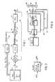
- the feedforward system of the preferred embodiment is shown in FIG. 1. It includes a path generator 13, which outputs desired path position data X k-1 , X k , X k+1 and X k over respective output lines 14, 15.
- the path data X k-n is the path position data for one-dimensional path motion.
- the output line 14 of the path generator 13 is connected to the input of a computing element 17 which applies a transfer function 1/G(Z) to the path data and outputs an open loop control voltage U open loop (k) on a line 18.
- the line 15 is connected as one input to a summer 27 which outputs an error signal E k on a line 16 to a computational element 21.
- the computational element 21 applies a feedback control transfer function D(Z) on the input E k and outputs a feedback control voltage U feedback (k) on a line 19.
- Lines 18 and 19 are connected to a summer 29 which adds the open loop and feedback control voltages U open loop , U feedback (k) to produce a total output control voltage U total (k) on a line 23.
- the line 23 is applied to the actual plant 25, which results in an actual path location or position Y k , which is outputted on a line 26.
- the transfer function of the actual plant 25 is represented by G*(Z).
- FIG. 2 shows an example of an actual plant 33, with an input voltage U(Z) resulting in an output position X(Z).
- the digital transfer function of this plant 33 is G*(Z) represents a plant including the voltage mode amplifier, motor, load and encoder, as illustrated, for example, in FIG. 3, to be described in further detail below.
- the open loop control is generated by solving a difference equation derived from the plant model G(z), which represents the dynamics of a DC motor, amplifier, lead screw, load and encoder.
- An equation of this form is called noncausal since the computation of the present control, U open loop (k) , requires the knowledge of a future event, namely X k+1 .
- Noncausal equations are not possible in feedback control since a future error, E k+1 is not known.
- the open loop calculation requires the future target point, X k+1 along the path.
- the target positions are precomputed using the well-known trapezoidal velocity profile and are thus available. If the target positions are not known in advance, then the target command could be delayed one sample period. Thus, the next target would be known one sample period before it is commanded.
- Equation (3) is implemented by computing element 17 in FIG. 1.
- Equation (3) may also be rewritten in terms of velocities V n as follows:
- U K ( 1 K ) [V K - (B)V K-1 + AU K-1 ]
- V n velocities V n as follows:
- U K ( 1 K ) [V K - (B)V K-1 + AU K-1 ]
- V n velocities V n as follows:
- U K ( 1 K ) [V K - (B)V K-1 + AU K-1 ]
- V n ( 1 K ) [V K - (B)V K-1 + AU K-1 ]
- the motor 34 controls movement of a robotic member 36 such as a mechanical arm along a selected axis, as is well known in the art.
- the digital control card or control section 28 includes a digital filter 37 embodied in, for example, a Motorola 68000 microprocessor operating at 12-1/2 MHz.
- the digital filter 37 may also be embodied in various forms of digital logic, other programmed processors, or special purpose signal processor circuitry.
- the digital filter 37 performs the function of the filter 17, filter 21, and summing junctions 27 and 29 in FIG. 1.
- the digital filter 37 receives the path or trajectory information provided by the path generator 13 and stored in the buffer 39.
- the digital filter 37 outputs the total control signal U total to the digital-to-analog converter 27.
- the digital-to-analog converter 27 in turn provides an analog control signal to the amplifier 29 for controlling the motor 34.
- the encoder 35 tracks the actual motor position and provides a feedback signal on line 31 to the digital filter 37.
- the DAC 27, amplifier 29, motor 34, encoder 35, and load 36 comprise the plant 25 illustrated in FIG. 1 having the transfer function G*(Z).
- each additional card 40 ... 41 contains its own buffer 39.
- Each buffer 39 receives path data for controlling motion on its particular dimension.
- the buffer 39 of card 28 may receive X path data
- buffer 39 of card 40 may receive Y path data
- the buffer 39 of card 41 may receive Z path data.
- Other dimensions include roll, pitch, yaw, etc., as known in the robotics art.
- a Pacific Scientific 2VM-62020-7 DC servo motor has been used for the motor 34 and a Disk Instruments rotary optical encoder M-98A-1000-ICLP yielding 4,000 counts per revolution with quadrature has been used for encoder 35.
- the amplifier 29 is a 40-volt, 12-amp Glentek GA45555 linear voltage mode amplifier.
- the digital-to-analog converter 27 is a Burr-Brown AD667.
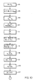
- FIGS. 4 and 5 A flowchart for programming the Motorola 68000 microprocessor to perform the digital filtering functions of digital filter 37 is illustrated in FIGS. 4 and 5. Performance of the routine starts at the beginning of every sample period with step 51. Execution of the filter algorithm continues sequentially with steps 57, 59, 61, etc. of FIGS. 4 and 5. The entire algorithm is computed within the sample period. The algorithm is performed autonomously by each digital filter 37 on each card 28, 40 ... 41 for the respective dimension whose path data is supplied to that card through the associated buffer 39.
- step 61 the feedback control D(z) is computed. This term D(z) is computed by multiplying a constant A1 times the error signal E k and adding to it a quantity denoted Prec 1, which is a precalculated quantity, as described hereafter.
- step 63 the next target, X k+1 is read from the buffer 39 into the processor.
- the open loop control parameter is calculated by multiplying a constant B1 times X k+1 and adding to it a second precalculated value Prec 2 as described hereafter.
- the total control signal is determined in accordance with the summing junction 29 in FIG. 1.
- step 69 a limit test is performed on the total control signal U total .
- the signal, U total is compared to parameters denoted DACMAX and DACMIN and clipped if necessary. These parameters are selected to limit the input voltage signal within a range matched to the amplifier 29.
- the control signal U total is then sent to the DAC 27 and then to the amp 29 and motor 34 in step 71.
- the parameters determined during this servo update are saved in step 73 for the next servo update 51.
- the routine then proceeds to block 75, where all possible terms for the next servo update 51 are calculated to minimize the time between the beginning of the sample period, step 51, and the output of U total to the DAC/amp/motor, step 73.
- the two parameters previously referred to Prec 1 and Prec 2 are calculated according to the equations established.
- all history terms are initially set to zero.
- the sample period is 1 millisecond and generates a high priority interrupt to the processor so that the beginning of the digital servo algorithm is synchronized to the beginning of every sample period.
- the path generator 13 can be run before starting the move or concurrently therewith.
- the path generator 13 may read out previously-stored path information, or may be a computer which calculates detailed trajectory data for a target path in response to general position commands, as desired.
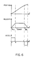
- FIGS. 6 and 7 illustrate typical profiles to which the preferred embodiment is applicable.
- FIG. 6 shows the position, velocity and acceleration profiles for a single axis point-to-point move under trapezoidal velocity profile constraints.
- a trapezoidal velocity profile has the inherent position and acceleration versus time profiles shown in FIG. 6. Notice that the acceleration has jump discontinuities at times a, b, c and d.
- FIG. 7 illustrates the velocity profiles of two coordinated axes which are each moving a distance equal to the area under their respective velocity curves. Note that the acceleration, deceleration and constant velocity duration times must be set equal for true coordination.
- the ratio of the peak velocities, accelerations and decelerations are set equal to the ratio of the move distances between axes.
- the axis which is limiting reduction of the move time is run at peak acceleration, deceleration and speed.
- the other axis parameters are scaled down according to the position ratios described above.
- motion on multiple axes is coordinated by controlling position and velocity through the whole range of the move.
- FIGS. 8 and 9 illustrate a typical three-dimensional move accomplished according to the preferred embodiment.
- the move particularly illustrated is movement of a wire by a wire bonding apparatus with respect to a part 77.
- FIG. 8 shows the three-dimensional move in XYZ coordinates
- FIG. 9 illustrates the move mapped into a Z and "R" axis where the R axis is composed of X and Y and forms a straight line from "a" to "h” in the XY plane.
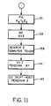
- FIGS. 10 and 11 illustrate exemplary steps for executing the movements depicted by FIGS. 8 and 9.
- the moves comprise seven segments, as follows: No. Segment Description 1 a-b Lift Z axis off part. 2 b-c XY axis move that can begin once Z is above a height denoted Z flag . 3 c-d Z axis move where notification once Z is above a height Z I1 is requested.
- the path generator 13 supplies the digital filter 37 for the Z axis with the target position array required to move the Z axis to Z b .
- the command 103 denoted "GO Z BEL Z > Z flag " is then executed wherein the digital filter 37 performs the routine illustrated in FIGS. 4 and 5 to bring the robot member to position b on the Z axis.
- the bell condition BEL Z > Z flag is set up in step 103 to indicate when the actual Z value is greater than Z flag so that the XY motion to X c , Y c can begin once Z is above some obstacle located at the height denoted by Z flag .
- step 105 the position arrays required to move the X axis to X c and the Y axis to Y c are supplied to the path control hardware by the path generator 13.
- step 107 after the bell condition Z > Z flag is satisfied, a "GO XY" command is executed to bring X and Y to X c , Y c , thereby completing segment bc.
- step 111 is executed wherein the position array to move Z to Z d is supplied by the path generator 13 to the position controller.
- the position controller begins the move to Z d in response to the array supplied by the path generator once X and Y have been commanded to X c , Y c .
- a bell may be armed to signal once the actual Z position is greater than a selected height value Z I1 .
- An interrupt is indicated at step 115 to signal the associated wire bonding apparatus that Z I1 has been passed.
- the associated wire bonding apparatus can then begin some external process such as closing a wire clamp.
- the arc depicted from point d to point g is executed by steps 119, 121, 125, 127, 131 and 133.
- the commands in these steps successively supply the position control apparatus with the arrays necessary to move X, Y and Z successively to X e , Y e , Z e ; X f , Y f , Z f ; and X g , Y g , Z g .
- the respective GO commands 121, 127 and 133 initiate the position control routine illustrated in FIGS. 4 and 5 for each dimension to successively move the robot member to the respective positions.
- the search Z command 139 (FIG. 11) indicates generation of a special trajectory array to Z.
- This array has embedded commands to search the Z axis in the down direction at a given velocity until "touch" is sensed.
- "GO Z PENDINM XY” starts the Z search once X and Y have completely settled at X g , Y g .
- the special trajectory array is supplied to the position control apparatus, which performs the operations illustrated in FIGS. 4 and 5 to bring the robot member to the desired position.
- the GO command 143 provides an interrupt to the associated apparatus once touchdown has occurred.
- the foregoing preferred embodiment achieves the combination of open loop and feedback control to more accurately position a robot or other member.
- the preferred embodiment coordinates motion on multiple axes by controlling position and velocity through the whole range of the move, as illustrated in connection with FIG. 7.
Abstract
Claims (12)
- Dispositif de commande d'axe convenant pour une machine robotisée, le dispositif de commande étant destiné à recevoir des informations (XK-1, XK, XK+1) de position d'une trajectoire recherchée afin de générer un signal de commande de position pour établir une position d'axe réelle, le dispositif de commande comportant :
des moyens (17 ; 37) destinés à générer un signal de commande de position en boucle ouverte (UOPENLOOP(K)) à partir des informations de position de trajectoire recherchée, les informations de position de trajectoire recherchée étant le seul signal lié à la position, utilisé pour générer le signal de commande de position en boucle ouverte ;
des moyens (27, 21 ; 37) qui, en réponse à la position d'axe réelle et à l'information (XK) de position de trajectoire recherchée, génèrent un signal de commande de rétro-action (UFEEDBACK(K)) ;
des moyens (29 ; 37, 27) destinés à générer un signal de commande de position (UTOTAL(K)) à partir du signal de commande de position en boucle ouverte et du signal de commande de rétro-action ;
caractérisé en ce que les moyens (17 ; 37) de génération de signal de commande de position en boucle ouverte appliquent une fonction de transfert (1/G(Z)) à l'information de position de trajectoire recherchée pour générer le signal de commande de position en boucle ouverte, la fonction de transfert étant l'inverse de la fonction de transfert (G*(Z)) d'un modèle de la machine. - Dispositif de commande d'axe selon la revendication 1, dans lequel les moyens (17 ; 37) de génération de signal de commande de position en boucle ouverte comprennent un filtre destiné à appliquer ladite fonction de transfert à l'information de position de trajectoire recherchée.
- Dispositif de commande d'axe selon la revendication 1 ou 2, dans lequel les moyens (27, 21 ; 37) destinés à générer un signal de commande de rétro-action comprennent un moyen (27) destiné à soustraire un signal représentant une information de position de trajectoire recherchée d'un signal représentant la position d'axe réelle pour produire un signal d'erreur (E(K)), et un moyen (21) destiné à appliquer une fonction de transfert (D(Z)) de commande de rétro-action au signal d'erreur (E(K)) pour produire le signal de commande à rétro-action.
- Dispositif de commande d'axe selon la revendication 1, 2 ou 3, dans lequel les moyens (29, 37, 27) destinés à générer le signal de commande de position comprennent un moyen (29) destiné à additionner le signal de commande à rétro-action et le signal de commande en boucle ouverte pour générer le signal de commande de position.
- Dispositif de commande d'axe selon la revendication 1, 2, 3 ou 4, dans lequel les moyens de génération du signal de commande de position en boucle ouverte, les moyens de génération du signal de commande à rétro-action et les moyens de génération du signal de commande de position comprennent les moyens à processeur numérique (28 ; 40 ; 41), l'information de position de trajectoire recherchée étant fournie sous forme numérique.
- Dispositif de commande d'axe selon la revendication 5, dans lequel les moyens (29 ; 37, 27) de génération de signal de commande de position comprennent un moyen à convertisseur numérique-analogique (27) destiné à produire un signal analogique de sortie de commande de position.
- Machine robotique comprenant un dispositif de commande d'axe selon l'une quelconque des revendications précédentes, la machine comportant en outre :
un moyen amplificateur (29) destiné à amplifier le signal de sortie de commande de position ;
un moyen à moteur (34) destiné à produire un mouvement de positionnement en réponse au signal de sortie du moyen amplificateur ; et
un moyen à codeur (35) destiné à suivre le mouvement de positionnement du moyen à moteur pour déterminer la position réelle de la machine. - Machine robotique selon la revendication 7, dans laquelle le moyen à amplificateur (27) comporte un moyen à amplificateur commandé en tension.
- Procédé convenant à la commande de positions d'axe dans une machine robotique, procédé dans lequel un signal de commande d'axe réel est généré à partir d'informations (XK-1, X(K), XK+1) de position de trajectoire recherchée, le procédé comprenant les étapes qui consistent :
à générer un signal (UOPENLOOP(K)) de position en boucle ouverte à partir des informations de position de trajectoire recherchée, les informations de position de trajectoire recherchée étant les seules informations liées à la position utilisées pour générer le signal de commande de position en boucle ouverte ;
à générer un signal (UFEEDBACK(K)) de commande à rétro-action à partir de la positon d'axe réelle et à partir de l'information (XK) de position de la trajectoire recherchée ;
à générer un signal (UTOTAL(K)) de commande de position à partir du signal de commande de position en boucle ouverte et du signal de commande à rétro-action,
caractérisé en ce que l'étape consistant à générer un signal de commande de position en boucle ouverte consiste à appliquer une fonction de transfert (1/G(Z)) à l'information de position de trajectoire recherchée pour générer le signal de commande de position en boucle ouverte, la fonction de transfert étant l'inverse de la fonction de transfert (G*(Z)) d'un modèle de la machine. - Procédé selon la revendication 9, dans lequel l'étape consistant à générer le signal de commande de position en boucle ouverte consiste à filtrer les informations (XK1, XK, XK+1) de position de trajectoire recherchée pour leur appliquer ladite fonction de transfert (1/G(Z)).
- Procédé selon la revendication 9 ou 10, dans lequel l'étape de génération du signal de commande à rétroaction consiste à soustraire un signal représentant l'information de position de trajectoire recherchée d'un signal représentant la position d'axe réelle pour produire un signal d'erreur (EK), et à appliquer une fonction (D(Z)) de transfert de commande à rétro-action au signal d'erreur (EK) pour produire le signal de commande à rétro-action.
- Procédé selon la revendication 9, 10 ou 11, dans lequel les étapes de génération du signal de commande de position en boucle ouverte, de génération du signal de commande à rétro-action et de génération du signal de commande de position sont effectuées sur des données numériques.
Applications Claiming Priority (2)
| Application Number | Priority Date | Filing Date | Title |
|---|---|---|---|
| US07/177,564 US4912753A (en) | 1988-04-04 | 1988-04-04 | Robot axis controller employing feedback and open loop (feedforward) control |
| US177564 | 1988-04-04 |
Publications (2)
| Publication Number | Publication Date |
|---|---|
| EP0375749A1 EP0375749A1 (fr) | 1990-07-04 |
| EP0375749B1 true EP0375749B1 (fr) | 1993-09-29 |
Family
ID=22649093
Family Applications (1)
| Application Number | Title | Priority Date | Filing Date |
|---|---|---|---|
| EP89904480A Expired - Lifetime EP0375749B1 (fr) | 1988-04-04 | 1989-03-27 | Unite de commande d'axe de robot, utilisant une commande a boucle a retroaction et ouverte |
Country Status (6)
| Country | Link |
|---|---|
| US (1) | US4912753A (fr) |
| EP (1) | EP0375749B1 (fr) |
| JP (1) | JPH03500101A (fr) |
| DE (1) | DE68909574T2 (fr) |
| IL (1) | IL89756A (fr) |
| WO (1) | WO1989009953A1 (fr) |
Families Citing this family (27)
| Publication number | Priority date | Publication date | Assignee | Title |
|---|---|---|---|---|
| US5175678A (en) * | 1990-08-15 | 1992-12-29 | Elsag International B.V. | Method and procedure for neural control of dynamic processes |
| US5444612A (en) * | 1991-04-16 | 1995-08-22 | Fanuc Ltd. | Adaptive PI control system |
| JP2840139B2 (ja) * | 1991-04-24 | 1998-12-24 | ファナック株式会社 | 予見繰り返し制御装置 |
| JPH0580810A (ja) * | 1991-09-20 | 1993-04-02 | Hitachi Ltd | サーボ制御方法及び装置 |
| US5353207A (en) * | 1992-06-10 | 1994-10-04 | Pavilion Technologies, Inc. | Residual activation neural network |
| US5255571A (en) * | 1992-06-25 | 1993-10-26 | United Parcel Service Of America, Inc. | Three degree of freedom actuator system |
| JP3485336B2 (ja) * | 1992-09-08 | 2004-01-13 | キャタピラー インコーポレイテッド | 乗物の位置を決定する方法及び装置 |
| KR0160998B1 (ko) * | 1992-09-18 | 1998-12-15 | 윤종용 | 로보트의 구동경로 계획방법 |
| US5825646A (en) | 1993-03-02 | 1998-10-20 | Pavilion Technologies, Inc. | Method and apparatus for determining the sensitivity of inputs to a neural network on output parameters |
| AU6358394A (en) * | 1993-03-02 | 1994-09-26 | Pavilion Technologies, Inc. | Method and apparatus for analyzing a neural network within desired operating parameter constraints |
| US5467281A (en) * | 1993-03-13 | 1995-11-14 | Toyoda Koki Kabushiki Kaisha | Controller for power steering apparatus |
| JPH08241126A (ja) * | 1995-03-02 | 1996-09-17 | Canon Inc | 同期位置制御方法および装置 |
| US6363289B1 (en) | 1996-09-23 | 2002-03-26 | Pavilion Technologies, Inc. | Residual activation neural network |
| SE509443C2 (sv) * | 1997-05-15 | 1999-01-25 | Asea Brown Boveri | Förfarande för övervakning av en manipulators rörelsestyrning |
| US6025686A (en) * | 1997-07-23 | 2000-02-15 | Harnischfeger Corporation | Method and system for controlling movement of a digging dipper |
| KR19990033511A (ko) * | 1997-10-24 | 1999-05-15 | 전주범 | 가상 현실 운동 재현기의 구동 제어 장치 |
| DE19846637A1 (de) * | 1998-10-09 | 2000-04-13 | Heidenhain Gmbh Dr Johannes | Verfahren und Schaltungsanordnung zur automatischen Parametrierung eines schnellen digitalen Drehzahlregelkreises |
| KR100342255B1 (ko) | 1999-06-25 | 2002-06-27 | 윤종용 | 로봇 구동용 모터의 속도제어방법 |
| US20020138171A1 (en) * | 2001-02-22 | 2002-09-26 | Mutoshi Fukutani | Numerical control method and numerically controlled allaratus |
| DE102004002142A1 (de) * | 2004-01-15 | 2005-08-11 | Robert Bosch Gmbh | Verfahren und Computerprogramm zum Generieren eines Modells für das Verhalten einer Steuereinrichtung |
| US6975087B1 (en) * | 2004-08-06 | 2005-12-13 | Delphi Technologies, Inc. | Closed-loop control system |
| US8000837B2 (en) * | 2004-10-05 | 2011-08-16 | J&L Group International, Llc | Programmable load forming system, components thereof, and methods of use |
| US7246005B2 (en) * | 2005-06-07 | 2007-07-17 | Arvin Technologies, Inc. | Method and apparatus for controlling a component by feed-forward closed-loop controller state modification |
| US20070142966A1 (en) * | 2005-12-20 | 2007-06-21 | Khalid Mirza | Process for moving a robot |
| JP4297123B2 (ja) * | 2006-03-14 | 2009-07-15 | トヨタ自動車株式会社 | 移動体の軌道追従制御システム及び軌道追従制御方法 |
| WO2008072618A1 (fr) * | 2006-12-12 | 2008-06-19 | University Of Electro-Communications | Contrôleur numérique |
| US10836038B2 (en) | 2014-05-21 | 2020-11-17 | Fanuc America Corporation | Learning path control |
Family Cites Families (29)
| Publication number | Priority date | Publication date | Assignee | Title |
|---|---|---|---|---|
| US30016A (en) * | 1860-09-11 | Book-latch | ||
| US3612976A (en) * | 1969-04-09 | 1971-10-12 | Inductosyn Corp | Position control system |
| GB1424353A (en) * | 1972-03-03 | 1976-02-11 | Cranfield Inst Of Tech | Machines for machining slots in workpieces |
| US3798430A (en) * | 1973-02-27 | 1974-03-19 | Giddings & Lewis | Reduction of servo following errors in position and velocity control systems of the iteratively computing type |
| FR2254056A1 (en) * | 1973-12-10 | 1975-07-04 | Mitsubishi Heavy Ind Ltd | Semi-open loop servo control system - permits closed loop operation until reference value is approached |
| US3940794A (en) * | 1974-06-19 | 1976-02-24 | International Business Machines Corporation | Stacked flexible record disk storage apparatus having enhanced disk separation |
| US4061952A (en) * | 1975-04-14 | 1977-12-06 | Cranfield Institute Of Technology | Computer-controlled machine tool |
| US4011437A (en) * | 1975-09-12 | 1977-03-08 | Cincinnati Milacron, Inc. | Method and apparatus for compensating for unprogrammed changes in relative position between a machine and workpiece |
| USRE30016E (en) | 1975-09-12 | 1979-05-29 | Cincinnati Milacron Inc. | Method and apparatus for compensating for unprogrammed changes in relative position between a machine and workpiece |
| US4093904A (en) * | 1976-02-04 | 1978-06-06 | Contraves Goerz Corporation | Multi-axis motion generator utilizing feedforward control |
| SE396479B (sv) * | 1976-02-09 | 1977-09-19 | Westbeck Navitele Ab | Anordning for att styra en lutningsanordning vid fordon |
| US4041287A (en) * | 1976-09-08 | 1977-08-09 | Giddings & Lewis, Inc. | Final servo control in NC systems |
| FR2396379A1 (fr) * | 1977-07-01 | 1979-01-26 | Thomson Brandt | Lecteur optique de disque d'information muni d'un dispositif d'acces automatique aux informations |
| GB2039078B (en) * | 1978-12-27 | 1982-11-24 | Ibm | Sampled data servo positioning system |
| US4302666A (en) * | 1979-11-13 | 1981-11-24 | The Boeing Company | Position control system of the discontinuous feedback type |
| US4345194A (en) * | 1980-12-01 | 1982-08-17 | The United States Of America As Represented By The United States Department Of Energy | Control system to reduce the effects of friction in drive trains of continuous-path-positioning systems |
| US4396049A (en) * | 1981-02-05 | 1983-08-02 | Calvert Manufacturing, Inc. | Backup roll arrangement for wood veneer lathe |
| US4389618A (en) * | 1981-04-15 | 1983-06-21 | The United States Of America As Represented By The Secretary Of The Navy | Adaptive feed-forward system |
| NL8204027A (nl) * | 1982-10-19 | 1984-05-16 | Hollandse Signaalapparaten Bv | Inrichting voor het stabiliseren van een, op een voer- of vaartuig aangebrachte rondzoekeenheid. |
| US4533991A (en) * | 1982-12-29 | 1985-08-06 | Storage Technology Corporation | Adaptive feedforward servo system |
| US4535372A (en) * | 1983-06-29 | 1985-08-13 | Storage Technology Corporation | Position tracking servo control systems and methods |
| EP0130248B1 (fr) * | 1983-06-30 | 1987-11-25 | International Business Machines Corporation | Servo-système d'alignement sur une piste pour une pile de disques |
| US4595027A (en) * | 1984-05-08 | 1986-06-17 | Philip Morris Incorporated | Rod weight control for a cigarette making machine |
| JPS60263206A (ja) * | 1984-06-11 | 1985-12-26 | Nissan Motor Co Ltd | マニピユレ−タの制御装置 |
| JPS61122720A (ja) * | 1984-11-20 | 1986-06-10 | Fujitsu Ltd | フイ−ドフオワ−ド補償付サ−ボ制御装置 |
| US4653360A (en) * | 1985-05-07 | 1987-03-31 | The Cross Company | CNC turning machine |
| US4617637A (en) * | 1985-07-09 | 1986-10-14 | Lifecare Services, Inc. | Servo control system for a reciprocating piston respirator |
| US4807153A (en) * | 1986-11-20 | 1989-02-21 | Unimation Inc. | Multiaxis digital robot control having a backup velocity monitor and protection system |
| JPH01148100A (ja) * | 1987-12-01 | 1989-06-09 | Matsushita Electric Ind Co Ltd | 位置制御装置 |
-
1988
- 1988-04-04 US US07/177,564 patent/US4912753A/en not_active Expired - Fee Related
-
1989
- 1989-03-27 JP JP1504340A patent/JPH03500101A/ja active Pending
- 1989-03-27 DE DE89904480T patent/DE68909574T2/de not_active Expired - Fee Related
- 1989-03-27 EP EP89904480A patent/EP0375749B1/fr not_active Expired - Lifetime
- 1989-03-27 IL IL89756A patent/IL89756A/xx unknown
- 1989-03-27 WO PCT/US1989/001260 patent/WO1989009953A1/fr active IP Right Grant
Also Published As
| Publication number | Publication date |
|---|---|
| EP0375749A1 (fr) | 1990-07-04 |
| US4912753A (en) | 1990-03-27 |
| IL89756A (en) | 1992-07-15 |
| DE68909574D1 (de) | 1993-11-04 |
| WO1989009953A1 (fr) | 1989-10-19 |
| IL89756A0 (en) | 1989-09-28 |
| DE68909574T2 (de) | 1994-05-05 |
| JPH03500101A (ja) | 1991-01-10 |
Similar Documents
| Publication | Publication Date | Title |
|---|---|---|
| EP0375749B1 (fr) | Unite de commande d'axe de robot, utilisant une commande a boucle a retroaction et ouverte | |
| US4893068A (en) | Digital servo employing switch mode lead/lag integrator | |
| US4617502A (en) | Method and apparatus for controlling a robot hand along a predetermined path | |
| US4604716A (en) | Method and apparatus for controlling a robot | |
| Yeh et al. | Analysis and design of the integrated controller for precise motion systems | |
| US5373221A (en) | Method and system for estimating robot tool center point speed | |
| US5248921A (en) | Servo motor control device | |
| US5587638A (en) | Flexible servo control method capable of specifying flexibility on working coordinates | |
| KR0160998B1 (ko) | 로보트의 구동경로 계획방법 | |
| US4859920A (en) | Interface system for servo controller | |
| US4553078A (en) | Servo control booster system for minimizing following error | |
| US4685067A (en) | Control system for program controlled manipulator having multiple triggered functions between programmed points | |
| US4629955A (en) | Method and apparatus for machine control | |
| US4041287A (en) | Final servo control in NC systems | |
| JPS6140602A (ja) | 工作機駆動装置のための制御最適化方法 | |
| US4214192A (en) | Path control apparatus for the computer directed control of a numerically controlled machine tool | |
| JPS61138308A (ja) | 産業用ロボツトの調節装置および方法 | |
| US4602196A (en) | Measurement method, and apparatus therefor | |
| JP3062606B2 (ja) | ニューラルネットワークを用いた適応制御装置 | |
| JPH0424198B2 (fr) | ||
| JPH0193805A (ja) | ロボットの教示データ作成方法 | |
| JP2594423B2 (ja) | 産業用ロボツトの制御装置 | |
| JPH0146939B2 (fr) | ||
| JP2802492B2 (ja) | ライントラッキング制御装置 | |
| JPH0623928B2 (ja) | ロボツトハンドの軌道修正方法 |
Legal Events
| Date | Code | Title | Description |
|---|---|---|---|
| PUAI | Public reference made under article 153(3) epc to a published international application that has entered the european phase |
Free format text: ORIGINAL CODE: 0009012 |
|
| 17P | Request for examination filed |
Effective date: 19891123 |
|
| AK | Designated contracting states |
Kind code of ref document: A1 Designated state(s): CH DE FR GB LI NL SE |
|
| 17Q | First examination report despatched |
Effective date: 19920306 |
|
| GRAA | (expected) grant |
Free format text: ORIGINAL CODE: 0009210 |
|
| STAA | Information on the status of an ep patent application or granted ep patent |
Free format text: STATUS: THE PATENT HAS BEEN GRANTED |
|
| AK | Designated contracting states |
Kind code of ref document: B1 Designated state(s): CH DE FR GB LI NL SE |
|
| PG25 | Lapsed in a contracting state [announced via postgrant information from national office to epo] |
Ref country code: LI Effective date: 19930929 Ref country code: FR Effective date: 19930929 Ref country code: CH Effective date: 19930929 |
|
| REF | Corresponds to: |
Ref document number: 68909574 Country of ref document: DE Date of ref document: 19931104 |
|
| REG | Reference to a national code |
Ref country code: CH Ref legal event code: PL |
|
| PGFP | Annual fee paid to national office [announced via postgrant information from national office to epo] |
Ref country code: SE Payment date: 19940216 Year of fee payment: 6 Ref country code: GB Payment date: 19940216 Year of fee payment: 6 |
|
| PGFP | Annual fee paid to national office [announced via postgrant information from national office to epo] |
Ref country code: DE Payment date: 19940217 Year of fee payment: 6 |
|
| EN | Fr: translation not filed | ||
| PGFP | Annual fee paid to national office [announced via postgrant information from national office to epo] |
Ref country code: NL Payment date: 19940331 Year of fee payment: 6 |
|
| PLBE | No opposition filed within time limit |
Free format text: ORIGINAL CODE: 0009261 |
|
| 26N | No opposition filed | ||
| EAL | Se: european patent in force in sweden |
Ref document number: 89904480.4 |
|
| PG25 | Lapsed in a contracting state [announced via postgrant information from national office to epo] |
Ref country code: GB Effective date: 19950327 |
|
| PG25 | Lapsed in a contracting state [announced via postgrant information from national office to epo] |
Ref country code: SE Effective date: 19950328 |
|
| PG25 | Lapsed in a contracting state [announced via postgrant information from national office to epo] |
Ref country code: NL Effective date: 19951001 |
|
| GBPC | Gb: european patent ceased through non-payment of renewal fee |
Effective date: 19950327 |
|
| NLV4 | Nl: lapsed or anulled due to non-payment of the annual fee |
Effective date: 19951001 |
|
| PG25 | Lapsed in a contracting state [announced via postgrant information from national office to epo] |
Ref country code: DE Effective date: 19951201 |
|
| EUG | Se: european patent has lapsed |
Ref document number: 89904480.4 |