EP0374679A2 - Method for producing a two-sided high-pressure discharge lamp - Google Patents
Method for producing a two-sided high-pressure discharge lamp Download PDFInfo
- Publication number
- EP0374679A2 EP0374679A2 EP89122833A EP89122833A EP0374679A2 EP 0374679 A2 EP0374679 A2 EP 0374679A2 EP 89122833 A EP89122833 A EP 89122833A EP 89122833 A EP89122833 A EP 89122833A EP 0374679 A2 EP0374679 A2 EP 0374679A2
- Authority
- EP
- European Patent Office
- Prior art keywords
- tube
- discharge vessel
- pinch
- lamp
- power supply
- Prior art date
- Legal status (The legal status is an assumption and is not a legal conclusion. Google has not performed a legal analysis and makes no representation as to the accuracy of the status listed.)
- Granted
Links
Images


Classifications
-
- H—ELECTRICITY
- H01—ELECTRIC ELEMENTS
- H01J—ELECTRIC DISCHARGE TUBES OR DISCHARGE LAMPS
- H01J9/00—Apparatus or processes specially adapted for the manufacture, installation, removal, maintenance of electric discharge tubes, discharge lamps, or parts thereof; Recovery of material from discharge tubes or lamps
- H01J9/24—Manufacture or joining of vessels, leading-in conductors or bases
- H01J9/245—Manufacture or joining of vessels, leading-in conductors or bases specially adapted for gas discharge tubes or lamps
- H01J9/247—Manufacture or joining of vessels, leading-in conductors or bases specially adapted for gas discharge tubes or lamps specially adapted for gas-discharge lamps
Definitions
- the invention relates to the manufacture of a lamp with the features designated in the preamble of the main claim.
- the invention relates in particular to the production of metal halide high-pressure discharge lamps with an electrical power consumption of at most 50 W, as have recently been increasingly proposed for the purpose of general lighting or for use in motor vehicle headlights.
- Such lamps have hitherto been produced by first closing a quartz tube which is open on both sides and then forming the olive-shaped shape at the location of the future discharge vessel by collecting the quartz glass. Then the tube end, which was initially closed, is opened again in further work steps and a pump tube is attached to the center of the discharge vessel.
- this object is achieved by the sequence of work steps set out in the main claim. Further details for the production of the metal halide high-pressure discharge lamps can be found in the subclaims. Since the work steps of filling and closing the discharge vessel take place in the high-purity atmosphere of the glovebox, contamination by foreign gases such as H2, O2 or H2O can be reduced to a minimum. By heating the still open tube inside the glovebox, the particle density in this area is reduced. This creates - after the sealing melting by means of a plasma torch in the glovebox and after the discharge vessel has cooled - a certain negative pressure inside, which, in conjunction with the temperature reduction to approx. ⁇ 100 ° C, enables the second pinch to be produced outside the glovebox.
- the process time is considerably shortened and the entire production process is simplified. Because of the there are no different wall thicknesses or inhomogeneities of any other type, which means that the radiation emission from the lamp is much more uniform than in the known lamps with a pump tube.
- the lamp is therefore particularly suitable for use in optical systems, for example in motor vehicle headlights, in which extremely precise adjustment and arrangement of the light / dark boundary are important.
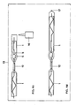
- FIG. 1a shows the tube 1 made of quartz glass cut to a length of approximately 150 mm.
- the outside diameter of the tube is approx. 4.5 mm, the inside diameter d is approx. 2 mm.
- both constrictions 4, 5 are placed in the center and at a defined distance from one another by means of the forming roller 3 (FIG. 1b).
- a nitrogen stream N 2 is passed through the tube 1 at a rate of 10 l / h from one side.
- the future discharge vessel 6 (FIG. 1c) is precisely delimited in its length of approximately 7.5 mm.
- the constriction 4 has a smaller clear diameter than the constriction 5. This results in a gas accumulation p of the nitrogen stream N 2 between the two constrictions in the heated area of the future discharge vessel 6, so that this area is somewhat inflated and its olive shape with an outer diameter of approx .5.5 mm.
- the prefabricated electrode system (FIG. 2) is squeezed into that end of the tube 1 which has the constriction 4 with the smaller diameter.
- the electrode system consists of an electrode 7 made of tungsten, a sealing film 8 made of molybdenum and a power supply 9 made of molybdenum.
- the electrode 7 is provided with a ball 10 at its end arranged in the discharge vessel 6.
- the power supply line 9 is bent in a zigzag shape in the yz plane, the angle ⁇ by which the curved power supply line 9 deviates from the xz plane being less than 45 °, preferably approximately 20 ° -30 °.
- the height h that is the amount by which the reversal point 11 of the curved power supply 9 deviates from the xz plane, is greater than half the inner diameter d of the tube 1. In practice, a ratio corresponding to h ⁇ 0.55 d proven.
- the you tion film 8 is aligned in the xz-plane, that is perpendicular to the yz-plane of the curved power supply 9.
- An electrode system shaped in this way holds itself within the tube 1 by the kinking or reversal points 11 of the power supply 9 being clamped against the inner wall of the tube. Once adjusted to its predetermined position, the electrode system maintains it until it is finally fixed.
- each power supply 9 To securely support the power supply 9 on the inner wall of the tube 1, at least three kink or reversal points 11 are attached to each power supply 9.
- a power supply 9 designed in this way centers itself in the axis of the tube 1.
- the electrode 7 in the discharge vessel 6 is also automatically centered in the x coordinate of the sealing film 8. Any possible decentration perpendicular to the plane of the sealing film 8, that is to say in the y coordinate, for example by bending the sealing film 8, is compensated for during the squeezing process.
- the first pinch 12 is then produced.
- the tube 1 in the area of the sealing film 8 is brought to a temperature of above approximately 2200 ° C. which is suitable for the deformation.
- an argon flow is passed through the preformed tube 1.
- the first pinch 12 is produced.
- the pinch that is adjacent to the constriction 4 with the smaller diameter is first sealed.
- the production of the pinch itself is a process known to the person skilled in lamp construction and is not shown separately in the figures.
- the tube 1 provided with the first pinch 12 is now subjected to high-vacuum annealing at> 400 ° C. and ⁇ 5 ⁇ 10 ⁇ 5 mbar when it is introduced into the glove box for cleaning.
- the glovebox 13 is filled with argon.
- the filling pressure does not deviate from the surrounding atmospheric pressure by more than a few 10 mbar.
- the argon filling gas of the glovebox 13 corresponds to the future filling gas of the metal halide high-pressure discharge lamp.
- the work steps within the glove box 13 are shown in FIG. 4.
- FIG. 4a shows the lamp of FIG. 3 pinched on one side in the glovebox 13.
- the filling substances consisting of a metal halide pill 14 and a mercury ball 15, and first the second electrode system (FIG. 4b) introduced.
- the filling substances fall through the still open constriction 5 with the larger diameter into the discharge vessel 6.
- the electrode system is, as before during the preparation for the first squeeze 12, adjusted in its self-retaining position at its predetermined position, so that the electrode 7 within of the discharge vessel 6 is arranged and the distance between the balls 10 of the two electrodes 7 is given its intended value.
- the open tube 1 is heated with a heating device. This causes a reduction in the particle density in the heated area.
- the quartz tube 1 is then sealed at its open end inside the glovebox 13 by means of a plasma torch 16 or a laser (FIG. 4c), so that only one melting tip 17 (FIG. 4d) remains.
- a plasma torch 16 or a laser FIG. 4c
- the lamp thus prefabricated has cooled down Due to the reduced particle density inside the discharge vessel there is a filling pressure which is approx. 300 mbar below the surrounding atmospheric pressure.
- the prefabricated lamp is now removed from the glovebox 13.
- the area around the sealing film 8 of the second electrode system is heated to the pinch temperature of approximately 2200 ° C. and the second pinch 18 (FIG. 5) is applied by squeezing the second electrode system.
- the area of the discharge vessel 6 is cooled to ⁇ 100 ° C. by means of cooled nitrogen in order to prevent the metal halide 14 and mercury 15 from evaporating.
- the lamp is removed from the squeezing device and the tube ends 1 projecting beyond the squeezes 12, 18 are removed.
- the zigzag part of the power supply lines 9 can also be removed.
- a finished metal halide high-pressure discharge lamp 19 is shown in FIG. 5.
Abstract
Description
Die Erfindung betrifft die Herstellung einer Lampe mit den im Oberbegriff des Hauptanspruchs bezeichneten Merkmalen. Die Erfindung betrifft insbesondere die Herstellung von Metallhalogenidhochdruckentladungslampen mit einer elektrischen Leistungsaufnahme von maximal 50 W, wie sie in letzter Zeit vermehrt zum Zweck der Allgemeinbeleuchtung oder zum Einsatz in Kraftfahrzeugscheinwerfern vorgeschlagen wurden. Solche Lampen wurden bisher hergestellt, indem ein beidseitig offenes Quarzrohr zuerst einseitig verschlossen und anschließend an der Stelle des künftigen Entladungsgefäßes durch Versammeln des Quarzglases dessen olivenförmige Gestalt ausgebildet wird. Danach werden in weiteren Arbeitsgängen das anfangs verschlossene Rohrende wieder geöffnet sowie ein Pumprohr mittig an das Entladungsgefäß angesetzt. Nachdem in die offenen Rohrenden jeweils ein Elektrodensystem eingeführt und eingeschmolzen wurde, werden die Füllsubstanzen und das Füllgas durch das Pumprohr in das Entladungsgefäß eingebracht und letztlich das Pumprohr abgeschmolzen. Dieses aufwendige, arbeitsintensive Herstellverfahren hat den gravierenden Nachteil, daß an dem ohnehin sehr kleinen Entladungsgefäß - seine Länge beträgt nur ca. 7,5 mm, sein Durchmesser nur ca. 5,5 mm - durch das Ansetzen und Abschmelzen des Pumprohres Inhomogenitäten in der Materialverteilung entstehen, die zum einen die Cold-Spot-Temperatur und damit die Lichtfarbe der Lampe nachteilig beeinflussen und zum anderen die von der Lampe emittierte Strahlung in einem nicht reproduzierbaren Maß streuen, was sich bei dem vorgesehenen Einsatz dieser Lampen in optischen Systemen besonders nachteilig bemerkbar macht.The invention relates to the manufacture of a lamp with the features designated in the preamble of the main claim. The invention relates in particular to the production of metal halide high-pressure discharge lamps with an electrical power consumption of at most 50 W, as have recently been increasingly proposed for the purpose of general lighting or for use in motor vehicle headlights. Such lamps have hitherto been produced by first closing a quartz tube which is open on both sides and then forming the olive-shaped shape at the location of the future discharge vessel by collecting the quartz glass. Then the tube end, which was initially closed, is opened again in further work steps and a pump tube is attached to the center of the discharge vessel. After an electrode system has been introduced and melted into each of the open tube ends, the filling substances and the filling gas are introduced through the pump tube into the discharge vessel and ultimately the pump tube is melted off. This complex, labor-intensive manufacturing process has the serious disadvantage that in the already very small discharge vessel - its length is only about 7.5 mm, its diameter is only about 5.5 mm - inhomogeneities in the material distribution due to the attachment and melting of the pump tube arise, on the one hand the cold spot temperature and thus adversely influencing the light color of the lamp and secondly scattering the radiation emitted by the lamp to a non-reproducible extent, which is particularly disadvantageous when these lamps are used in optical systems.
Es ist Aufgabe der Erfindung, ein einfaches Herstellverfahren für die in Frage kommenden Lampen zu schaffen, bei dem keine inhomogene Materialverteilung am Entladungsgefäß auftritt, um die zuvor beschriebenen Nachteile auszuschalten.It is an object of the invention to provide a simple manufacturing process for the lamps in question, in which there is no inhomogeneous material distribution on the discharge vessel in order to eliminate the disadvantages described above.
Diese Aufgabe wird erfindungsgemäß durch die im Hauptanspruch aufgeführte Folge von Arbeitsschritten gelöst. Den Unteransprüchen sind weitere Details für die Herstellung der Metallhalogenid-Hochdruckentladungslampen entnehmbar. Da die Arbeitsschritte des Füllens und Verschließens des Entladungsgefäßes in der hochreinen Atmosphäre der Glovebox erfolgen, können Verunreinigungen durch Fremdgase, wie H₂, O₂ oder H₂O, auf ein Minimum reduziert werden. Durch die Aufheizung des noch offenen Rohres innerhalb der Glovebox wird eine Reduzierung der Teilchendichte in diesem Bereich bewirkt. Hierdurch entsteht - nach dem Dichtschmelzen mittels eines Plasmabrenners in der Glovebox und nach dem Abkühlen des Entladungsgefäßes - in seinem Inneren ein gewisser Unterdruck, der es in Verbindung mit der Temperaturabsenkung auf ca. < 100 °C ermöglicht, die zweite Quetschung außerhalb der Glovebox herzustellen. Mit der beschriebenen Herstellungsweise wird eine erhebliche Verkürzung der Verfahrenszeit und eine Vereinfachung des gesamten Herstellverfahrens erreicht. Aufgrund des am Entla dungsgefäß nicht mehr vorhandenen Pumprohres treten auch dort keine unterschiedlichen Wanddicken oder Inhomogenitäten anderer Art auf, wodurch die Strahlungsemission der Lampe sehr viel gleichmäßiger erfolgt als bei den bekannten Lampen mit Pumprohr. Die Lampe ist deshalb für den Einsatz in optischen Systemen besonders geeignet, wie z.B. in Kraftfahrzeugscheinwerfern, bei denen es auf eine äußerst präzise Justierung und Anordnung der Hell-/Dunkelgrenze ankommt.According to the invention, this object is achieved by the sequence of work steps set out in the main claim. Further details for the production of the metal halide high-pressure discharge lamps can be found in the subclaims. Since the work steps of filling and closing the discharge vessel take place in the high-purity atmosphere of the glovebox, contamination by foreign gases such as H₂, O₂ or H₂O can be reduced to a minimum. By heating the still open tube inside the glovebox, the particle density in this area is reduced. This creates - after the sealing melting by means of a plasma torch in the glovebox and after the discharge vessel has cooled - a certain negative pressure inside, which, in conjunction with the temperature reduction to approx. <100 ° C, enables the second pinch to be produced outside the glovebox. With the method of production described, the process time is considerably shortened and the entire production process is simplified. Because of the there are no different wall thicknesses or inhomogeneities of any other type, which means that the radiation emission from the lamp is much more uniform than in the known lamps with a pump tube. The lamp is therefore particularly suitable for use in optical systems, for example in motor vehicle headlights, in which extremely precise adjustment and arrangement of the light / dark boundary are important.
Die Erfindung wird nachstehend anhand von 5 Figuren näher erläutert. Es zeigen
- Figuren 1a bis c die Herstellung eines vorgeformten Entladungsgefäßes
Figur 2 ein ElektrodensystemFigur 3 das Entladungsgefäß mit vorhandener erster Quetschung- Figuren 4a bis d die Bearbeitungsschritte in der Glovebox
Figur 5 eine fertige Metallhalogenidhochdruckentladungslampe
- Figures 1a to c, the manufacture of a preformed discharge vessel
- Figure 2 shows an electrode system
- Figure 3 shows the discharge vessel with an existing first pinch
- Figures 4a to d the processing steps in the glovebox
- Figure 5 shows a finished metal halide high pressure discharge lamp
Figur 1a zeigt das auf eine Länge von ca. 150 mm geschnittene Rohr 1 aus Quarzglas. Der Außendurchmesser des Rohres beträgt ca. 4,5 mm, der Innendurchmesser d ca. 2 mm.FIG. 1a shows the
Mit Hilfe der Flammen 2 wird zunächst das in Rotation versetzte Rohr 1 erwärmt und nach Erreichen der Ver formungstemperatur werden mittels der Formrolle 3 gleichzeitig beide Einschnürungen 4, 5 mittig und in einem definierten Abstand zueinander angebracht (Fig. 1b). Während des Erwärmens und des Verformens wird von einer Seite ein Stickstoffstrom N₂ mit einer Menge von 10 l/h durch das Rohr 1 geführt. Durch das Anbringen der Einschnürungen 4, 5 wird das zukünftige Entladungsgefäß 6 (Fig. 1c) in seiner Länge von ca. 7,5 mm genau abgegrenzt. Die Einschnürung 4 weist einen geringeren lichten Durchmesser auf als die Einschnürung 5. Hierdurch entsteht zwischen den beiden Einschnürungen im erwärmten Bereich des zukünftigen Entladungsgefäßes 6 ein Gasstau p des Stickstoffstromes N₂, so daß dieser Bereich etwas aufgeblasen wird und seine olivenförmige Gestalt mit einem Außendurchmesser von ca. 5,5 mm annimmt.With the help of the
Im nächsten Arbeitsgang wird das vorgefertigte Elektrodensystem (Fig. 2) in dasjenige Ende des Rohres 1 eingequetscht, das die Einschnürung 4 mit dem geringeren Durchmesser aufweist. Das Elektrodensystem besteht aus einer Elektrode 7 aus Wolfram, einer Dichtungsfolie 8 aus Molybdän sowie aus einer Stromzuführung 9 aus Molybdän. Die Elektrode 7 ist an ihrem im Entladungsgefäß 6 angeordneten Ende mit einer Kugel 10 versehen. Die Stromzuführung 9 ist in der y-z-Ebene zickzackförmig gebogen, wobei der Winkel α , um den die gebogene Stromzuführung 9 von der x-z-Ebene abweicht, kleiner als 45°, vorzugsweise ca. 20° - 30° ist. Die Höhe h, das ist jener Betrag, um den der Umkehrpunkt 11 der gebogenen Stromzuführung 9 von der x-z-Ebene abweicht, ist größer als der halbe Innendurchmesser d des Rohres 1. In der Praxis hat sich ein Verhältnis entsprechend h ≃ 0, 55 d bewährt. Die Dich tungsfolie 8 ist in der x-z-Ebene ausgerichtet, also senkrecht zur y-z-Ebene der gebogenen Stromzuführung 9. Ein derart geformtes Elektrodensystem haltert sich innerhalb des Rohres 1 von selbst, indem die Knick- oder Umkehrpunkte 11 der Stromzuführung 9 klemmend an der Rohrinnenwand anliegen. Einmal an seiner vorbestimmten Position einjustiert, behält das Elektrodensystem diese bis zur endgültigen Fixierung bei. Zur sicheren Abstützung der Stromzuführung 9 an der Innenwand des Rohres 1 sind mindestens drei Knick- oder Umkehrpunkte 11 an jeder Stromzuführung 9 angebracht. Eine derart gestaltete Stromzuführung 9 zentriert sich in der Achse des Rohres 1 von selbst. Dadurch wird auch automatisch eine Zentrierung der Elektrode 7 im Entladungsgefäß 6 in der x-Koordinate der Dichtungsfolie 8 erreicht. Eine eventuell mögliche Dezentrierung senkrecht zur Ebene der Dichtungsfolie 8, also in der y-Koordinate, z.B. durch Verbiegen der Dichtungsfolie 8, wird beim Quetschvorgang ausgeglichen.In the next step, the prefabricated electrode system (FIG. 2) is squeezed into that end of the
Wie aus der Figur 3 ersichtlich, wird anschließend die erste Quetschung 12 hergestellt. Hierfür wird das Rohr 1 im Bereich der Dichtungsfolie 8 auf eine für die Verformung geeignete Temperatur von oberhalb ca. 2200 °C gebracht. Gleichzeitig wird ein Argonstrom durch das vorgeformte Rohr 1 geleitet. Nachdem die Quetschtemperatur erreicht ist, wird die erste Quetschung 12 hergestellt. Es wird zuerst die Quetschung abgedichtet, die der Einschnürung 4 mit dem geringeren Durchmesser benachbart ist. Die Herstellung der Quetschung an sich ist ein dem Fachmann im Lampenbau bekannter Vorgang und in den Figuren nicht gesondert dargestellt.As can be seen from FIG. 3, the
Das mit der ersten Quetschung 12 versehene Rohr 1 wird nun beim Einschleusen in die Glovebox zur Reinigung einer Hochvakuumglühung bei > 400 °C und < 5 x 10⁻⁵ mbar unterzogen. Die Glovebox 13 ist mit Argon gefüllt. Der Fülldruck weicht um nicht mehr als einige 10 mbar vom umgebenden Atmosphärendruck ab. Das Füllgas Argon der Glovebox 13 entspricht dem künftigen Füllgas der Metallhalogenidhochdruckentladungslampe. Die Arbeitsschritte innerhalb der Glovebox 13 sind in der Figur 4 dargestellt.The
Figur 4a zeigt die einseitig gequetschte Lampe der Figur 3 in der Glovebox 13. Als Nächstes werden in das wieder erkaltete Entladungsgefäß 6 zuerst die Füllsubstanzen, bestehend aus einer Metallhalogenid-Pille 14 und einer Quecksilber-Kugel 15, und weiterhin das zweite Elektrodensystem (Fig. 4b) eingebracht. Die Füllsubstanzen fallen durch die noch offene Einschnürung 5 mit dem größeren Durchmesser in das Entladungsgefäß 6. Das Elektrodensystem wird, wie schon zuvor bei der Vorbereitung auf die erste Quetschung 12, selbsthalternd an seine ihm vorbestimmte Stelle in Position einjustiert, so daß die Elektrode 7 innerhalb des Entladungsgefäßes 6 angeordnet ist und der Abstand der Kugeln 10 beider Elektroden 7 genau seinen vorgesehenen Wert erhält. Anschließend wird das offene Rohr 1 mit einer Heizvorrichtung aufgeheizt. Dadurch wird eine Reduzierung der Teilchendichte in dem erwärmten Bereich bewirkt. Danach wird das Quarzrohr 1 an seinem offenen Ende innerhalb der Glovebox 13 mittels eines Plasmabrenners 16 oder eines Lasers dichtgeschmolzen (Fig. 4c), so daß nur noch eine Abschmelzspitze 17 (Fig. 4d) verbleibt. Nach der Abkühlung der auf diese Weise vorgefertigten Lampe entsteht aufgrund der reduzierten Teilchendichte im Innern des Entladungsgefäßes ein um ca. 300 mbar unter dem umgebenden Atmosphärendruck liegender Fülldruck. Die vorgefertigte Lampe wird jetzt wieder der Glovebox 13 entnommen. Danach wird, wie schon bei der ersten Quetschung 12 beschrieben, der Bereich um die Dichtungsfolie 8 des zweiten Elektrodensystems auf die Quetschtemperatur von ca. 2200 °C aufgeheizt und die zweite Quetschung 18 (Fig. 5) angebracht, indem das zweite Elektrodensystem eingequetscht wird. Während des Aufheiz- und Quetschvorganges wird der Bereich des Entladungsgefäßes 6 mittels gekühltem Stickstoff auf < 100 °C gekühlt, um ein Verdampfen des Metallhalogenids 14 und Quecksilbers 15 zu verhindern.FIG. 4a shows the lamp of FIG. 3 pinched on one side in the
Abschließend wird die Lampe der Quetschvorrichtung entnommen und es werden die über die Quetschungen 12, 18 hinausstehenden Rohrenden 1 entfernt. Ebenso kann der zickzackförmig ausgeführte Teil der Stromzuführungen 9 entfernt werden. Eine fertige Metallhalogenidhochdruckentladungslampe 19 ist in Figur 5 dargestellt.Finally, the lamp is removed from the squeezing device and the tube ends 1 projecting beyond the
Claims (12)
Applications Claiming Priority (2)
| Application Number | Priority Date | Filing Date | Title |
|---|---|---|---|
| DE3842769A DE3842769A1 (en) | 1988-12-19 | 1988-12-19 | METHOD FOR PRODUCING A TWO-SIDED HIGH PRESSURE DISCHARGE LAMP |
| DE3842769 | 1988-12-19 |
Publications (3)
| Publication Number | Publication Date |
|---|---|
| EP0374679A2 true EP0374679A2 (en) | 1990-06-27 |
| EP0374679A3 EP0374679A3 (en) | 1991-05-08 |
| EP0374679B1 EP0374679B1 (en) | 1995-03-15 |
Family
ID=6369557
Family Applications (1)
| Application Number | Title | Priority Date | Filing Date |
|---|---|---|---|
| EP89122833A Expired - Lifetime EP0374679B1 (en) | 1988-12-19 | 1989-12-11 | Method for producing a two-sided high-pressure discharge lamp |
Country Status (5)
| Country | Link |
|---|---|
| EP (1) | EP0374679B1 (en) |
| JP (1) | JP2804134B2 (en) |
| DD (1) | DD290504A5 (en) |
| DE (2) | DE3842769A1 (en) |
| HU (1) | HU203170B (en) |
Cited By (5)
| Publication number | Priority date | Publication date | Assignee | Title |
|---|---|---|---|---|
| EP0892423A2 (en) * | 1997-07-17 | 1999-01-20 | Ushiodenki Kabushiki Kaisha | Discharge lamp of the short arc type and process for production thereof |
| EP0944109A1 (en) * | 1998-03-16 | 1999-09-22 | Matsushita Electric Industrial Co., Ltd. | Discharge lamp and method of producing the same |
| WO2005122206A2 (en) * | 2004-06-09 | 2005-12-22 | Patent-Treuhand- Gesellschaft Für Elektrische Glühlampen Mbh | Method for machining a lamp and lamp machined by said method |
| WO2009115118A1 (en) * | 2008-03-19 | 2009-09-24 | Osram Gesellschaft mit beschränkter Haftung | Gas discharge lamp and method for producing a gas discharge lamp |
| CN107029635A (en) * | 2017-05-25 | 2017-08-11 | 桂林理工大学 | A kind of method and device of prepare compound under vacuum conditions |
Families Citing this family (1)
| Publication number | Priority date | Publication date | Assignee | Title |
|---|---|---|---|---|
| GB2423862A (en) | 2005-03-04 | 2006-09-06 | Heraeus Noblelight Ltd | High-pressure discharge lamp having constructional details for reducing devitrification of glass |
Citations (7)
| Publication number | Priority date | Publication date | Assignee | Title |
|---|---|---|---|---|
| US3305289A (en) * | 1963-05-09 | 1967-02-21 | Gen Electric | Electric lamp manufacture |
| US3689799A (en) * | 1970-09-14 | 1972-09-05 | Gen Electric | Method of dosing lamps |
| DE2127526A1 (en) * | 1971-06-03 | 1972-12-14 | Licentia Gmbh | Method for carrying out the method for generating a high vacuum and Vornch |
| JPS51128179A (en) * | 1975-04-30 | 1976-11-08 | Iwasaki Electric Co Ltd | Discharge lamp manufacturing method |
| EP0055416A2 (en) * | 1980-12-26 | 1982-07-07 | Kabushiki Kaisha Toshiba | Method of sealing a tube using a laser beam |
| EP0204061A1 (en) * | 1985-05-23 | 1986-12-10 | Lumalampan Aktiebolag | A compact low-pressure mercury vapour discharge lamp and a method for its manufacture |
| DE3702813A1 (en) * | 1986-02-12 | 1987-08-13 | Tungsram Reszvenytarsasag | METHOD AND DEVICE FOR THE PRODUCTION OF DISCHARGE TUBES FOR SODIUM STEAM DISCHARGE LAMPS |
Family Cites Families (2)
| Publication number | Priority date | Publication date | Assignee | Title |
|---|---|---|---|---|
| JPS60127633A (en) * | 1983-12-12 | 1985-07-08 | Toshiba Corp | Production of metal vapor discharge lamp |
| DE3842770A1 (en) | 1988-12-19 | 1990-06-21 | Patent Treuhand Ges Fuer Elektrische Gluehlampen Mbh | METHOD FOR PRODUCING A TWO-SIDED HIGH PRESSURE DISCHARGE LAMP |
-
1988
- 1988-12-19 DE DE3842769A patent/DE3842769A1/en not_active Withdrawn
-
1989
- 1989-12-11 EP EP89122833A patent/EP0374679B1/en not_active Expired - Lifetime
- 1989-12-11 DE DE58909112T patent/DE58909112D1/en not_active Expired - Lifetime
- 1989-12-18 HU HU896665A patent/HU203170B/en not_active IP Right Cessation
- 1989-12-18 DD DD89335842A patent/DD290504A5/en not_active IP Right Cessation
- 1989-12-19 JP JP1327508A patent/JP2804134B2/en not_active Expired - Lifetime
Patent Citations (7)
| Publication number | Priority date | Publication date | Assignee | Title |
|---|---|---|---|---|
| US3305289A (en) * | 1963-05-09 | 1967-02-21 | Gen Electric | Electric lamp manufacture |
| US3689799A (en) * | 1970-09-14 | 1972-09-05 | Gen Electric | Method of dosing lamps |
| DE2127526A1 (en) * | 1971-06-03 | 1972-12-14 | Licentia Gmbh | Method for carrying out the method for generating a high vacuum and Vornch |
| JPS51128179A (en) * | 1975-04-30 | 1976-11-08 | Iwasaki Electric Co Ltd | Discharge lamp manufacturing method |
| EP0055416A2 (en) * | 1980-12-26 | 1982-07-07 | Kabushiki Kaisha Toshiba | Method of sealing a tube using a laser beam |
| EP0204061A1 (en) * | 1985-05-23 | 1986-12-10 | Lumalampan Aktiebolag | A compact low-pressure mercury vapour discharge lamp and a method for its manufacture |
| DE3702813A1 (en) * | 1986-02-12 | 1987-08-13 | Tungsram Reszvenytarsasag | METHOD AND DEVICE FOR THE PRODUCTION OF DISCHARGE TUBES FOR SODIUM STEAM DISCHARGE LAMPS |
Non-Patent Citations (1)
| Title |
|---|
| PATENT ABSTRACTS OF JAPAN, Band 1, Nr. 15, 23. März 1977, Seite 1195 M 76; & JP-A-51 128 179 (IWASAKI DENKI) 11-08-1976 * |
Cited By (8)
| Publication number | Priority date | Publication date | Assignee | Title |
|---|---|---|---|---|
| EP0892423A2 (en) * | 1997-07-17 | 1999-01-20 | Ushiodenki Kabushiki Kaisha | Discharge lamp of the short arc type and process for production thereof |
| EP0892423A3 (en) * | 1997-07-17 | 1999-09-22 | Ushiodenki Kabushiki Kaisha | Discharge lamp of the short arc type and process for production thereof |
| EP0944109A1 (en) * | 1998-03-16 | 1999-09-22 | Matsushita Electric Industrial Co., Ltd. | Discharge lamp and method of producing the same |
| US6791271B2 (en) | 1998-03-16 | 2004-09-14 | Matsushita Electric Industrial Co., Ltd. | Discharge lamp and method of producing the same |
| WO2005122206A2 (en) * | 2004-06-09 | 2005-12-22 | Patent-Treuhand- Gesellschaft Für Elektrische Glühlampen Mbh | Method for machining a lamp and lamp machined by said method |
| WO2005122206A3 (en) * | 2004-06-09 | 2008-03-06 | Patent Treuhand Ges Fuer Elektrische Gluehlampen Mbh | Method for machining a lamp and lamp machined by said method |
| WO2009115118A1 (en) * | 2008-03-19 | 2009-09-24 | Osram Gesellschaft mit beschränkter Haftung | Gas discharge lamp and method for producing a gas discharge lamp |
| CN107029635A (en) * | 2017-05-25 | 2017-08-11 | 桂林理工大学 | A kind of method and device of prepare compound under vacuum conditions |
Also Published As
| Publication number | Publication date |
|---|---|
| DE3842769A1 (en) | 1990-06-21 |
| JPH02223131A (en) | 1990-09-05 |
| HU896665D0 (en) | 1990-02-28 |
| JP2804134B2 (en) | 1998-09-24 |
| HU203170B (en) | 1991-05-28 |
| EP0374679A3 (en) | 1991-05-08 |
| DE58909112D1 (en) | 1995-04-20 |
| EP0374679B1 (en) | 1995-03-15 |
| DD290504A5 (en) | 1991-05-29 |
| HUT52893A (en) | 1990-08-28 |
Similar Documents
| Publication | Publication Date | Title |
|---|---|---|
| DE2835904C2 (en) | Use of an assembly consisting of an electrode and a supply line | |
| DE19710204A1 (en) | Arc-discharge tube with glass tube made of quartz used for lighting | |
| EP0386588B1 (en) | Low-pressure mercury discharge lamp | |
| EP0374679B1 (en) | Method for producing a two-sided high-pressure discharge lamp | |
| DE19928996A1 (en) | Quartz glass arc tube and pinch seals for an arc discharge lamp | |
| EP0374677B1 (en) | Method for producing a two-sided high-pressure discharge lamp | |
| EP0374676B1 (en) | Method for producing a two-sided high-pressure discharge lamp | |
| DE2732060C2 (en) | Electric fluorescent lamp | |
| DE19623499A1 (en) | Process for producing a halogen incandescent lamp | |
| EP0591777A2 (en) | Process for manufacturing a low power, high pressure discharge lamp having a single pinch, and high pressure discharge lamps | |
| DE3320919C2 (en) | ||
| DE3112821A1 (en) | ELECTRIC LAMP WITH A BOTTLE MELTING DESIGNED AS A CRUSH AND ITS DEVICE AND METHOD FOR THE PRODUCTION THEREOF | |
| DE2529004A1 (en) | OBJECT WITH A GLASS PART INTO WHICH A METAL PART IS MELTED | |
| EP1754238B1 (en) | Method for machining a lamp and lamp machined by said method | |
| EP0219860B1 (en) | Process for manufacturing a metal halide high-pressure discharge lamp having a single pinch, and a lamp manufactured according to this process | |
| CH621889A5 (en) | ||
| EP0369370B1 (en) | Method of manufacturing a lamp vessel | |
| DE975461C (en) | Electron beam tubes, in particular television picture tubes, with a tube piston made of metal | |
| DE19647827B4 (en) | Method for producing a fluorescent lamp | |
| DE10117664C1 (en) | Connecting sleeve used as a component of a low pressure glass refining device comprises a supporting core made from high temperature resistant material, and a sleeve surrounding the core | |
| DE10150452C1 (en) | Process for the production of a vitreous body and use of the vitreous body | |
| EP0676910B1 (en) | Method for manufacturing curved radiators, especially incandescent halogen lamps | |
| DE1004732B (en) | Process for the production of a partially mirrored, tubular incandescent lamp | |
| DE3838696A1 (en) | METHOD FOR PRODUCING A LAMP VESSEL | |
| EP1196937B1 (en) | Method for producing a lamp |
Legal Events
| Date | Code | Title | Description |
|---|---|---|---|
| PUAI | Public reference made under article 153(3) epc to a published international application that has entered the european phase |
Free format text: ORIGINAL CODE: 0009012 |
|
| AK | Designated contracting states |
Kind code of ref document: A2 Designated state(s): DE FR GB IT NL SE |
|
| 17P | Request for examination filed |
Effective date: 19901220 |
|
| PUAL | Search report despatched |
Free format text: ORIGINAL CODE: 0009013 |
|
| AK | Designated contracting states |
Kind code of ref document: A3 Designated state(s): DE FR GB IT NL SE |
|
| 17Q | First examination report despatched |
Effective date: 19930628 |
|
| GRAA | (expected) grant |
Free format text: ORIGINAL CODE: 0009210 |
|
| AK | Designated contracting states |
Kind code of ref document: B1 Designated state(s): DE FR GB IT NL SE |
|
| REF | Corresponds to: |
Ref document number: 58909112 Country of ref document: DE Date of ref document: 19950420 |
|
| ITF | It: translation for a ep patent filed |
Owner name: STUDIO JAUMANN |
|
| ET | Fr: translation filed | ||
| GBT | Gb: translation of ep patent filed (gb section 77(6)(a)/1977) |
Effective date: 19950605 |
|
| PLBE | No opposition filed within time limit |
Free format text: ORIGINAL CODE: 0009261 |
|
| STAA | Information on the status of an ep patent application or granted ep patent |
Free format text: STATUS: NO OPPOSITION FILED WITHIN TIME LIMIT |
|
| 26N | No opposition filed | ||
| REG | Reference to a national code |
Ref country code: GB Ref legal event code: IF02 |
|
| PGFP | Annual fee paid to national office [announced via postgrant information from national office to epo] |
Ref country code: NL Payment date: 20051205 Year of fee payment: 17 |
|
| PGFP | Annual fee paid to national office [announced via postgrant information from national office to epo] |
Ref country code: GB Payment date: 20051208 Year of fee payment: 17 Ref country code: SE Payment date: 20051208 Year of fee payment: 17 |
|
| PGFP | Annual fee paid to national office [announced via postgrant information from national office to epo] |
Ref country code: FR Payment date: 20051216 Year of fee payment: 17 |
|
| PG25 | Lapsed in a contracting state [announced via postgrant information from national office to epo] |
Ref country code: SE Free format text: LAPSE BECAUSE OF NON-PAYMENT OF DUE FEES Effective date: 20061212 |
|
| PGFP | Annual fee paid to national office [announced via postgrant information from national office to epo] |
Ref country code: IT Payment date: 20061231 Year of fee payment: 18 |
|
| PG25 | Lapsed in a contracting state [announced via postgrant information from national office to epo] |
Ref country code: NL Free format text: LAPSE BECAUSE OF NON-PAYMENT OF DUE FEES Effective date: 20070701 |
|
| EUG | Se: european patent has lapsed | ||
| GBPC | Gb: european patent ceased through non-payment of renewal fee |
Effective date: 20061211 |
|
| NLV4 | Nl: lapsed or anulled due to non-payment of the annual fee |
Effective date: 20070701 |
|
| REG | Reference to a national code |
Ref country code: FR Ref legal event code: ST Effective date: 20070831 |
|
| PG25 | Lapsed in a contracting state [announced via postgrant information from national office to epo] |
Ref country code: GB Free format text: LAPSE BECAUSE OF NON-PAYMENT OF DUE FEES Effective date: 20061211 |
|
| PG25 | Lapsed in a contracting state [announced via postgrant information from national office to epo] |
Ref country code: FR Free format text: LAPSE BECAUSE OF NON-PAYMENT OF DUE FEES Effective date: 20070102 |
|
| PGFP | Annual fee paid to national office [announced via postgrant information from national office to epo] |
Ref country code: DE Payment date: 20090220 Year of fee payment: 20 |
|
| PG25 | Lapsed in a contracting state [announced via postgrant information from national office to epo] |
Ref country code: IT Free format text: LAPSE BECAUSE OF NON-PAYMENT OF DUE FEES Effective date: 20071211 |