EP0374550B1 - Dispositif additionnel, par exemple pour une fraiseuse - Google Patents
Dispositif additionnel, par exemple pour une fraiseuse Download PDFInfo
- Publication number
- EP0374550B1 EP0374550B1 EP89122237A EP89122237A EP0374550B1 EP 0374550 B1 EP0374550 B1 EP 0374550B1 EP 89122237 A EP89122237 A EP 89122237A EP 89122237 A EP89122237 A EP 89122237A EP 0374550 B1 EP0374550 B1 EP 0374550B1
- Authority
- EP
- European Patent Office
- Prior art keywords
- turntable
- adapter
- machining
- spindle
- attachment unit
- Prior art date
- Legal status (The legal status is an assumption and is not a legal conclusion. Google has not performed a legal analysis and makes no representation as to the accuracy of the status listed.)
- Expired - Lifetime
Links
- 238000003801 milling Methods 0.000 title claims description 10
- 238000003754 machining Methods 0.000 claims description 23
- 230000006835 compression Effects 0.000 claims description 3
- 238000007906 compression Methods 0.000 claims description 3
- 238000005096 rolling process Methods 0.000 claims description 2
- 230000008878 coupling Effects 0.000 claims 1
- 238000010168 coupling process Methods 0.000 claims 1
- 238000005859 coupling reaction Methods 0.000 claims 1
- ZZUFCTLCJUWOSV-UHFFFAOYSA-N furosemide Chemical compound C1=C(Cl)C(S(=O)(=O)N)=CC(C(O)=O)=C1NCC1=CC=CO1 ZZUFCTLCJUWOSV-UHFFFAOYSA-N 0.000 claims 1
- 238000005498 polishing Methods 0.000 description 5
- 238000007790 scraping Methods 0.000 description 2
- 125000006850 spacer group Chemical group 0.000 description 2
- 239000011248 coating agent Substances 0.000 description 1
- 238000000576 coating method Methods 0.000 description 1
- 238000000227 grinding Methods 0.000 description 1
- 238000000034 method Methods 0.000 description 1
- 230000002093 peripheral effect Effects 0.000 description 1
- 238000007789 sealing Methods 0.000 description 1
- 238000004381 surface treatment Methods 0.000 description 1
- 238000002604 ultrasonography Methods 0.000 description 1
Images

Classifications
-
- B—PERFORMING OPERATIONS; TRANSPORTING
- B23—MACHINE TOOLS; METAL-WORKING NOT OTHERWISE PROVIDED FOR
- B23Q—DETAILS, COMPONENTS, OR ACCESSORIES FOR MACHINE TOOLS, e.g. ARRANGEMENTS FOR COPYING OR CONTROLLING; MACHINE TOOLS IN GENERAL CHARACTERISED BY THE CONSTRUCTION OF PARTICULAR DETAILS OR COMPONENTS; COMBINATIONS OR ASSOCIATIONS OF METAL-WORKING MACHINES, NOT DIRECTED TO A PARTICULAR RESULT
- B23Q37/00—Metal-working machines, or constructional combinations thereof, built-up from units designed so that at least some of the units can form parts of different machines or combinations; Units therefor in so far as the feature of interchangeability is important
-
- B—PERFORMING OPERATIONS; TRANSPORTING
- B23—MACHINE TOOLS; METAL-WORKING NOT OTHERWISE PROVIDED FOR
- B23Q—DETAILS, COMPONENTS, OR ACCESSORIES FOR MACHINE TOOLS, e.g. ARRANGEMENTS FOR COPYING OR CONTROLLING; MACHINE TOOLS IN GENERAL CHARACTERISED BY THE CONSTRUCTION OF PARTICULAR DETAILS OR COMPONENTS; COMBINATIONS OR ASSOCIATIONS OF METAL-WORKING MACHINES, NOT DIRECTED TO A PARTICULAR RESULT
- B23Q1/00—Members which are comprised in the general build-up of a form of machine, particularly relatively large fixed members
- B23Q1/25—Movable or adjustable work or tool supports
- B23Q1/44—Movable or adjustable work or tool supports using particular mechanisms
- B23Q1/50—Movable or adjustable work or tool supports using particular mechanisms with rotating pairs only, the rotating pairs being the first two elements of the mechanism
- B23Q1/54—Movable or adjustable work or tool supports using particular mechanisms with rotating pairs only, the rotating pairs being the first two elements of the mechanism two rotating pairs only
-
- B—PERFORMING OPERATIONS; TRANSPORTING
- B24—GRINDING; POLISHING
- B24B—MACHINES, DEVICES, OR PROCESSES FOR GRINDING OR POLISHING; DRESSING OR CONDITIONING OF ABRADING SURFACES; FEEDING OF GRINDING, POLISHING, OR LAPPING AGENTS
- B24B41/00—Component parts such as frames, beds, carriages, headstocks
- B24B41/002—Grinding heads
-
- B—PERFORMING OPERATIONS; TRANSPORTING
- B24—GRINDING; POLISHING
- B24D—TOOLS FOR GRINDING, BUFFING OR SHARPENING
- B24D9/00—Wheels or drums supporting in exchangeable arrangement a layer of flexible abrasive material, e.g. sandpaper
- B24D9/08—Circular back-plates for carrying flexible material
-
- Y—GENERAL TAGGING OF NEW TECHNOLOGICAL DEVELOPMENTS; GENERAL TAGGING OF CROSS-SECTIONAL TECHNOLOGIES SPANNING OVER SEVERAL SECTIONS OF THE IPC; TECHNICAL SUBJECTS COVERED BY FORMER USPC CROSS-REFERENCE ART COLLECTIONS [XRACs] AND DIGESTS
- Y10—TECHNICAL SUBJECTS COVERED BY FORMER USPC
- Y10T—TECHNICAL SUBJECTS COVERED BY FORMER US CLASSIFICATION
- Y10T409/00—Gear cutting, milling, or planing
- Y10T409/30—Milling
- Y10T409/30448—Milling with detachable or auxiliary cutter support to convert cutting action
-
- Y—GENERAL TAGGING OF NEW TECHNOLOGICAL DEVELOPMENTS; GENERAL TAGGING OF CROSS-SECTIONAL TECHNOLOGIES SPANNING OVER SEVERAL SECTIONS OF THE IPC; TECHNICAL SUBJECTS COVERED BY FORMER USPC CROSS-REFERENCE ART COLLECTIONS [XRACs] AND DIGESTS
- Y10—TECHNICAL SUBJECTS COVERED BY FORMER USPC
- Y10T—TECHNICAL SUBJECTS COVERED BY FORMER US CLASSIFICATION
- Y10T409/00—Gear cutting, milling, or planing
- Y10T409/30—Milling
- Y10T409/306664—Milling including means to infeed rotary cutter toward work
- Y10T409/307672—Angularly adjustable cutter head
-
- Y—GENERAL TAGGING OF NEW TECHNOLOGICAL DEVELOPMENTS; GENERAL TAGGING OF CROSS-SECTIONAL TECHNOLOGIES SPANNING OVER SEVERAL SECTIONS OF THE IPC; TECHNICAL SUBJECTS COVERED BY FORMER USPC CROSS-REFERENCE ART COLLECTIONS [XRACs] AND DIGESTS
- Y10—TECHNICAL SUBJECTS COVERED BY FORMER USPC
- Y10T—TECHNICAL SUBJECTS COVERED BY FORMER US CLASSIFICATION
- Y10T409/00—Gear cutting, milling, or planing
- Y10T409/30—Milling
- Y10T409/309296—Detachable or repositionable tool head
Definitions
- the invention relates to an attachment, in particular a polishing head or the like, for attachment to a machine tool of the type specified in the preamble of claim 1.
- Such an attachment is known from EP-A-139 819 which contains a column-shaped stand which is fastened to a workpiece table and on which a bearing block is mounted in a manually adjustable manner.
- an adapter On one side of the bracket-type bearing block, an adapter is installed in a height-adjustable manner, in which a turntable is mounted so that it can rotate about a horizontal axis.
- This turntable carries an off-center holder in which a hand drill can be clamped manually.
- This attachment is not suitable for complex program-controlled machining centers.
- Some types of processing e.g. B. the fine machining of the workpiece surfaces (finishing, scraping, polishing), but can not be easily integrated into program-controlled machining processes of machining workpiece machining, because in particular the fine and ultra-fine machining of workpiece surfaces requires long machining times in which the machine tool is then not suitable other operations are available. For this reason, special machines had previously been used for the fine machining of workpiece surfaces and similar special work processes. On the other hand, however, there are longer rest periods in every company, in which the entire machine park is not or only partially used, such as. B. Night shifts, weekends and public holidays.
- the object of the invention is to provide an attachment, in particular a polishing head or the like, which can be easily attached to the spindle housing of a milling machine and enables various machining operations on a workpiece with the aid of the machine's own drive means and its own drive.
- the invention enables further use of the program-controlled milling machines for the lengthy surface machining of even complex-shaped workpieces, in that the machining device is attached to the headstock at the beginning of long rest breaks and carries out the machining during the rest period, with the aid of the machine's own path control.
- tensioning elements are arranged according to the invention between the support body and the turntable rotatably mounted therein with the aid of the work spindle, which compensate for the play present in the drive train of the work spindle and ensure jerk-free pivoting movements and secure positioning of the processing device in a set inclined position.
- tensioning elements can expediently contain an end ring fastened to the supporting body with pressure elements arranged therein in the form of magnetic coils or compression springs which press against the bearing shell of a rolling bearing for the turntable and / or also against the turntable with an adjustable force.
- the attachment according to the invention is mounted on the end face of a headstock, in the lower part of which the horizontal spindle is arranged and which preferably carries a swivel head with a vertical milling head which can be pivoted between an upper rest position and a working position, preferably on a 45 ° inclined plane above the horizontal spindle.
- the adapter consists of a dimensionally stable support plate, which in its lower part - opposite the horizontal spindle - has a partially conical opening for mounting the turntable and is mounted with its upper part on the surface of the swivel head that is free of the vertical milling head.
- surfaces of workpieces in particular can be finely machined by scraping or rotating attack by a reaming tool.
- a plate-shaped tool at the end of a shaft that is oriented transversely to the spindle axis via a universal joint that performs rotating, circumferential or translational movements on the workpiece surface.
- a horizontal work spindle 3 is mounted, which is driven via a spur gear pair 4, 5 and a main shaft 6 by a drive (not shown) consisting of an electric motor and a gear block.
- a drive (not shown) consisting of an electric motor and a gear block.
- the work spindle 3 protrudes slightly beyond the vertical end wall 7 of the spindle housing 2.
- Above this vertical end wall 7 there is an inclined surface 8 at an angle of 45 °, on which a swivel head 9 is rotatably mounted about the 45 ° axis 10. This swivel head is rotatably fixed on the inclined surface 8 by means of corresponding guiding and locking means.
- a further milling head 11 is mounted on the horizontal surface of the swivel head 9, the individual parts of which do not protrude into the working area in front of the front of the spindle housing in this parking position.
- Such a headstock is described in DE-PS 29 44 983.
- a machining device 12 for surface machining a workpiece 13 by means of an adapter 14 is attached to the end face of the headstock 1.
- the adapter 14 contains a dimensionally stable support plate 15, which is mounted on the front vertical side of the swivel head 9 by a plurality of screw bolts 16 and fixing pins 17.
- a turntable 19 is mounted, on the projecting end face of which the housing 20 of the implement is mounted.
- the longitudinal axis 21 of this implement runs in a plane perpendicular to the longitudinal axis 22 of the work spindle.
- a profiled Cutout 23 in the turntable 19 engages the work spindle 3 with its projecting end in a form-fitting manner, so that when this work spindle 3 is rotated, the turntable 19 is also rotated together with the machining tool 12 firmly attached to it.
- the turntable 19 immediately behind its conical section has a toroidal bearing surface for a ring of balls 28, which is supported by a bearing ring 24 in the recess of the support plate 15 are held.
- a tuning disk 29 is arranged between this bearing ring 24 and an end ring 25.
- Several pressure members 26, e.g. B. compression springs and / or electromagnets are arranged in the end ring 25 defined by clamping bolts on the support body 15, which press against the bearing ring 24 via the tuning or spacer disk 29.
- a spacer or sealing ring 27 is located between the cylindrical end part of the turntable 19 and the inner peripheral surface of the end ring 25.
- the work spindle 3 is non-rotatably connected to the latter by the positive engagement of its projecting end in the correspondingly designed section of the turntable 19, the processing device 12 being rotated into a desired inclined position by means of its drive by means of a program-controlled rotation of the work spindle is pivoted, as indicated by dash-dotted lines in Fig. 2.
- the pivot angle is detected by a rotary encoder or protractor 50, which at the end of the elongated shaft 6 or - as shown - Can be attached to the work spindle 3 and delivers position signals to the program control of the machine.
- a drive motor (not shown) is arranged in the housing 20 of the processing device 12, the output shaft of which is possibly coupled to a shaft 30 via a gear.
- the pneumatic or electric drive motor can set the shaft 30 and the disk-shaped tool 32 connected to it via a universal joint 31 in rotary movements or in reciprocating vibrations and is supplied via a connection 33 either with compressed air or with electrical current.
- a housing 34 which forms part of the universal joint 31, is fastened to the tool disc 32 carrying a grinding, polishing or lapping coating.
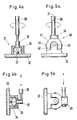
- a ball segment 35 is accommodated in the housing 34 in a rotationally fixed and movable manner, which is fastened to the shaft 30 by means of a sleeve 36 and is supported on the inner surface of the tool disk 32 by means of a spring 37. 4 and 5, two possible types of connection and movement of the tool disc are shown.
- the tool design according to FIGS. 5a and 5b has a universal joint, a so-called universal joint 40 with two brackets 41, 42 which are offset at right angles and which are mounted on two bolts 43, 44 which intersect at right angles.
- the shaft 30 is fixed eccentrically in a sleeve 45, so that the tool disk 32 executes a circular movement around the shaft axis 21.
- 5b is in the position the tool shank 30 is fixed in a transverse bore of the shank 45 and the tool arrangement executes translatory oscillating movements.
- the adapter 14 instead of the support plate shown can also have a different holder for the turntable 19 with clamping means which, for. B. on a conventional headstock - without swivel head. It is essential that the pivoting of the machining device 12 shown in FIG. 2 about the spindle axis 22, which is as deep as possible, takes place practically free of play through the horizontal work spindle 3 and its program-controlled drive train.
- processing equipment e.g. B. polishing heads or devices for electroerosive or for ultrasound processing of possibly coated workpieces.
Landscapes
- Engineering & Computer Science (AREA)
- Mechanical Engineering (AREA)
- Machine Tool Units (AREA)
- Constituent Portions Of Griding Lathes, Driving, Sensing And Control (AREA)
- Finish Polishing, Edge Sharpening, And Grinding By Specific Grinding Devices (AREA)
- Gripping On Spindles (AREA)
Claims (6)
- Appareil rapporté pour machines-outils, comportant un adaptateur (14) pouvant être monté sur la face frontale d'un élément (1) de la machine-outil, un disque rotatif (19) logé dans l'adaptateur (14) et un appareil d'usinage (12) fixé sur le disque rotatif (19),
caractérisé en ce que l'adaptateur (14) peut être montré sur un boîtier de broche (2) d'une machine à fraiser,
en ce que le disque rotatif (19) présente des moyens d'accouplement (23) pour être relié solidairement en rotation avec la broche (3) horizontale de la machine à fraiser, ainsi que des éléments de serrage (24-28) pour la compensation du jeu,
et en ce que le boîtier (20) de l'appareil d'usinage (12) peut être pivoté dans un plan transversal perpendiculaire à l'axe (22) de la broche. - Appareil rapporté selon la revendication 1, caractérisé en ce que le boîtier (20) de l'appareil d'usinage (12) est monté transversalement à l'axe (22) de la broche sur le disque rotatif (19), et en ce qu'il présente un alésage cylindrique pour recevoir une unité d'usinage avec un entraînement séparé pour un outil (32) fixé de manière articulée à l'extrémité d'une tige (30).
- Appareil rapporté selon l'une quelconque des revendications 1 ou 2, caractérisé en ce que l'adaptateur (14) est formé comme une plaque indéformable qui présente dans sa partie inférieure une ouverture en partie conique pour recevoir le disque rotatif (19) et les éléments de serrage (24-28), et qui est montée avec sa partie supérieure sur une tête pivotante (9) de la poupée porte-fraise (1).
- Appareil rapporté selon l'une ou l'autre des revendications 1 et 3, caractérisé en ce que les éléments de serrage (24-28) comportent un anneau terminal (25) fixé sur l'adaptateur (14), des organes de pression (26) agencés dans celui-ci en décalage angulaire et une rondelle d'ajustement (29) qui repose en contact sous pression sur le coussinet (24) d'un palier à roulements (23) du disque de rotation (19).
- Appareil rapporté selon la revendication 4, caractérisé en ce que les organes de pression (26) sont des électroaimants et/ou des ressorts de pression.
- Appareil rapporté selon l'une quelconque des revendications 1 à 5, caractérisé en ce que l'outil (32) en forme de disque servant au finissage de surfaces (13) de pièces est relié à la tige (30) de l'appareil par une articulation universelle (31 ou 40).
Applications Claiming Priority (2)
| Application Number | Priority Date | Filing Date | Title |
|---|---|---|---|
| DE8815854U | 1988-12-21 | ||
| DE8815854U DE8815854U1 (de) | 1988-12-21 | 1988-12-21 | Anbau-Gerät für z.B. Fräsmaschinen |
Publications (3)
| Publication Number | Publication Date |
|---|---|
| EP0374550A2 EP0374550A2 (fr) | 1990-06-27 |
| EP0374550A3 EP0374550A3 (fr) | 1991-11-13 |
| EP0374550B1 true EP0374550B1 (fr) | 1994-08-17 |
Family
ID=6831007
Family Applications (1)
| Application Number | Title | Priority Date | Filing Date |
|---|---|---|---|
| EP89122237A Expired - Lifetime EP0374550B1 (fr) | 1988-12-21 | 1989-12-01 | Dispositif additionnel, par exemple pour une fraiseuse |
Country Status (5)
| Country | Link |
|---|---|
| US (1) | US4998852A (fr) |
| EP (1) | EP0374550B1 (fr) |
| JP (1) | JPH02212064A (fr) |
| DE (2) | DE8815854U1 (fr) |
| ES (1) | ES2061904T3 (fr) |
Families Citing this family (4)
| Publication number | Priority date | Publication date | Assignee | Title |
|---|---|---|---|---|
| JPH0768465A (ja) * | 1993-09-01 | 1995-03-14 | Aoyama:Kk | 半自動研磨機具 |
| CN103056689A (zh) * | 2013-01-21 | 2013-04-24 | 昆山宾达精密配件有限公司 | 汽车零件加工用旋转治具 |
| CN105798368B (zh) * | 2014-12-30 | 2018-02-06 | 武汉重型机床集团有限公司 | 附件铣头主轴定位结构 |
| TW202228883A (zh) * | 2021-01-26 | 2022-08-01 | 日商發那科股份有限公司 | 進行刮削加工之機器人、機器人系統、方法及電腦程式 |
Citations (1)
| Publication number | Priority date | Publication date | Assignee | Title |
|---|---|---|---|---|
| EP0139819A2 (fr) * | 1983-10-29 | 1985-05-08 | Robert Wolff | Support pour une perceuse à main |
Family Cites Families (10)
| Publication number | Priority date | Publication date | Assignee | Title |
|---|---|---|---|---|
| US642355A (en) * | 1899-02-11 | 1900-01-30 | Alexander M I Mcleod | Rubber for surfacing stone, marble, & c. |
| US2227410A (en) * | 1937-07-29 | 1940-12-31 | Ingersoll Milling Machine Co | Machine tool |
| DE950102C (de) * | 1954-04-02 | 1956-10-04 | Ruhrstahl Ag | Lagerung fuer eine um eine senkrechte Achse umlaufende Scheibe, insbesondere fuer die Planscheibe einer Werkzeugmaschine, vorzugsweise eines Senkrecht-Bohr- und Drehwerkes |
| DE1239542B (de) * | 1961-01-27 | 1967-04-27 | Hans Deckel Dr Ing | Lagerung fuer Werkzeugspindeln |
| US3483796A (en) * | 1967-06-21 | 1969-12-16 | Innocenti Soc Generale | Angularly adjustable headstock attachment for use on machine tools |
| US3690220A (en) * | 1970-04-29 | 1972-09-12 | Fresco Ind Inc | Helically-tracking milling assembly with tiltable thread cutting head |
| DE2944983C2 (de) * | 1979-11-07 | 1982-07-22 | Maho Werkzeugmaschinenbau Babel & Co, 8962 Pfronten | Spindelstock für eine Universal-Fräs- und Bohrmaschine |
| SE441901B (sv) * | 1981-07-30 | 1985-11-18 | Itzchak Lapsker | Anordning for ytbearbetning med hog noggrannhet av ett arbetsstycke |
| US4557645A (en) * | 1984-02-27 | 1985-12-10 | Colt Industries Operating Corporation | Tooling attachment adaptor assembly |
| IT1173463B (it) * | 1984-03-23 | 1987-06-24 | Andrea Spa D | Testa a fresare nonche' a forare per macchina utensile |
-
1988
- 1988-12-21 DE DE8815854U patent/DE8815854U1/de not_active Expired
-
1989
- 1989-12-01 DE DE58908213T patent/DE58908213D1/de not_active Expired - Fee Related
- 1989-12-01 EP EP89122237A patent/EP0374550B1/fr not_active Expired - Lifetime
- 1989-12-01 ES ES89122237T patent/ES2061904T3/es not_active Expired - Lifetime
- 1989-12-20 JP JP1328554A patent/JPH02212064A/ja active Pending
- 1989-12-21 US US07/454,074 patent/US4998852A/en not_active Expired - Fee Related
Patent Citations (1)
| Publication number | Priority date | Publication date | Assignee | Title |
|---|---|---|---|---|
| EP0139819A2 (fr) * | 1983-10-29 | 1985-05-08 | Robert Wolff | Support pour une perceuse à main |
Also Published As
| Publication number | Publication date |
|---|---|
| US4998852A (en) | 1991-03-12 |
| ES2061904T3 (es) | 1994-12-16 |
| DE8815854U1 (de) | 1989-02-02 |
| DE58908213D1 (de) | 1994-09-22 |
| EP0374550A3 (fr) | 1991-11-13 |
| EP0374550A2 (fr) | 1990-06-27 |
| JPH02212064A (ja) | 1990-08-23 |
Similar Documents
| Publication | Publication Date | Title |
|---|---|---|
| DE102007009843B4 (de) | Verfahren zur Schleifbearbeitung eines Maschinenbauteils und Schleifmaschine zur Durchführung des Verfahrens | |
| WO1999039873A1 (fr) | Broche de ponçage | |
| DE69808785T2 (de) | Aussenschleifmaschine | |
| DE2937976C2 (de) | Maschine zum Schleifen oder Fräsen von konvexen und/oder konkaven sphärischen Flächen | |
| DE69303283T2 (de) | Vorrichtung zum dynamischen auswuchten eines sich drehenden korpers | |
| EP4058237A1 (fr) | Machine à meuler circulaire dotée d'une unité de dressage | |
| EP0374550B1 (fr) | Dispositif additionnel, par exemple pour une fraiseuse | |
| EP2161099B1 (fr) | Affûteuse | |
| EP0098987B1 (fr) | Appareil pour le réglage radial d'un outil d'alésage | |
| DE3902612C2 (fr) | ||
| DE3915199C1 (en) | Grinder for vehicle brake discs - incorporates opposed grinding wheels and reciprocating spindles | |
| DE3434140C1 (de) | Vorrichtung zur Feinstbearbeitung von umlaufenden Kurbelzapfen von Kurbelwellen u.dgl. | |
| DE3239914A1 (de) | Schleifmaschine zum schleifen der spanflaeche von spiralgenuteten werkzeugen | |
| DE3217631A1 (de) | Geraet zur feinstbearbeitung von werkstueckflaechen | |
| DE2146137C3 (de) | Maschine zum Schleifen oder Polieren von rotationssymmetrischen Werkstücken | |
| DE2442199C3 (de) | Einrichtung an einer Schleifmaschine zum Aufsetzen und Abnehmen des Schleifwerkzeugs | |
| DE1752992A1 (de) | Vorrichtung zum Schleifen der Kugelrillen von Kugelumlaufspindeln | |
| DE727663C (de) | Laeppmaschine zur Metallbearbeitung | |
| DD297589A5 (de) | Spann- und positioniereinrichtung | |
| DE19800515A1 (de) | Verfahren zur Aufarbeitung verformter Kegelinnenoberflächen der Werkzeugaufnahmen an Spindeln von Bearbeitungszentren | |
| DE4214462A1 (de) | Verfahren und vorrichtung zum schleifen von formstempeln | |
| DD265095A1 (de) | Vorrichtung mit pendelartig auslenkbarem werkzeughalter fuer entgratewerkzeuge | |
| DE2442199A1 (de) | Einrichtung fuer das aufsetzen und das abnehmen des schleifwerkzeuges auf die bzw. von der schleifspindel einer schleifmaschine | |
| DD213872A1 (de) | Universalrundschleifmaschine | |
| DE20200450U1 (de) | Vorrichtung zum zerspanenden Bearbeiten langgestreckter Werkstücke |
Legal Events
| Date | Code | Title | Description |
|---|---|---|---|
| PUAI | Public reference made under article 153(3) epc to a published international application that has entered the european phase |
Free format text: ORIGINAL CODE: 0009012 |
|
| AK | Designated contracting states |
Kind code of ref document: A2 Designated state(s): CH DE ES FR GB IT LI |
|
| PUAL | Search report despatched |
Free format text: ORIGINAL CODE: 0009013 |
|
| AK | Designated contracting states |
Kind code of ref document: A3 Designated state(s): CH DE ES FR GB IT LI |
|
| 17P | Request for examination filed |
Effective date: 19920513 |
|
| 17Q | First examination report despatched |
Effective date: 19921026 |
|
| GRAA | (expected) grant |
Free format text: ORIGINAL CODE: 0009210 |
|
| AK | Designated contracting states |
Kind code of ref document: B1 Designated state(s): CH DE ES FR GB IT LI |
|
| REF | Corresponds to: |
Ref document number: 58908213 Country of ref document: DE Date of ref document: 19940922 |
|
| ITF | It: translation for a ep patent filed | ||
| GBT | Gb: translation of ep patent filed (gb section 77(6)(a)/1977) |
Effective date: 19941103 |
|
| ET | Fr: translation filed | ||
| PLBE | No opposition filed within time limit |
Free format text: ORIGINAL CODE: 0009261 |
|
| STAA | Information on the status of an ep patent application or granted ep patent |
Free format text: STATUS: NO OPPOSITION FILED WITHIN TIME LIMIT |
|
| 26N | No opposition filed | ||
| REG | Reference to a national code |
Ref country code: GB Ref legal event code: 732E |
|
| REG | Reference to a national code |
Ref country code: CH Ref legal event code: PUE Owner name: GILDEMEISTER AKTIENGESELLSCHAFT TRANSFER- DECKEL M Ref country code: CH Ref legal event code: PFA Free format text: MAHO AKTIENGESELLSCHAFT TRANSFER- DECKEL MAHO AKTIENGESELLSCHAFT Ref country code: CH Ref legal event code: NV Representative=s name: MICHELI & CIE |
|
| REG | Reference to a national code |
Ref country code: ES Ref legal event code: PC2A Owner name: DECKEL MAHO GMBH |
|
| REG | Reference to a national code |
Ref country code: FR Ref legal event code: CD |
|
| REG | Reference to a national code |
Ref country code: FR Ref legal event code: TP |
|
| PGFP | Annual fee paid to national office [announced via postgrant information from national office to epo] |
Ref country code: GB Payment date: 19981130 Year of fee payment: 10 Ref country code: FR Payment date: 19981130 Year of fee payment: 10 |
|
| PGFP | Annual fee paid to national office [announced via postgrant information from national office to epo] |
Ref country code: ES Payment date: 19981216 Year of fee payment: 10 |
|
| PGFP | Annual fee paid to national office [announced via postgrant information from national office to epo] |
Ref country code: DE Payment date: 19990226 Year of fee payment: 10 |
|
| PGFP | Annual fee paid to national office [announced via postgrant information from national office to epo] |
Ref country code: CH Payment date: 19990304 Year of fee payment: 10 |
|
| PG25 | Lapsed in a contracting state [announced via postgrant information from national office to epo] |
Ref country code: GB Free format text: LAPSE BECAUSE OF NON-PAYMENT OF DUE FEES Effective date: 19991201 |
|
| PG25 | Lapsed in a contracting state [announced via postgrant information from national office to epo] |
Ref country code: LI Free format text: LAPSE BECAUSE OF NON-PAYMENT OF DUE FEES Effective date: 19991231 Ref country code: CH Free format text: LAPSE BECAUSE OF NON-PAYMENT OF DUE FEES Effective date: 19991231 |
|
| GBPC | Gb: european patent ceased through non-payment of renewal fee |
Effective date: 19991201 |
|
| PG25 | Lapsed in a contracting state [announced via postgrant information from national office to epo] |
Ref country code: FR Free format text: LAPSE BECAUSE OF NON-PAYMENT OF DUE FEES Effective date: 20000831 |
|
| PG25 | Lapsed in a contracting state [announced via postgrant information from national office to epo] |
Ref country code: DE Free format text: LAPSE BECAUSE OF NON-PAYMENT OF DUE FEES Effective date: 20001003 |
|
| REG | Reference to a national code |
Ref country code: FR Ref legal event code: ST |
|
| PG25 | Lapsed in a contracting state [announced via postgrant information from national office to epo] |
Ref country code: ES Free format text: LAPSE BECAUSE OF NON-PAYMENT OF DUE FEES Effective date: 20001202 |
|
| REG | Reference to a national code |
Ref country code: ES Ref legal event code: FD2A Effective date: 20010113 |
|
| PG25 | Lapsed in a contracting state [announced via postgrant information from national office to epo] |
Ref country code: IT Free format text: LAPSE BECAUSE OF NON-PAYMENT OF DUE FEES Effective date: 20051201 |