EP0374489A2 - Verfahren und Vorrichtung zur Herstellung von zylindrischen Unterstützungselementen in Beschneidevorrichtungen - Google Patents
Verfahren und Vorrichtung zur Herstellung von zylindrischen Unterstützungselementen in Beschneidevorrichtungen Download PDFInfo
- Publication number
- EP0374489A2 EP0374489A2 EP89121327A EP89121327A EP0374489A2 EP 0374489 A2 EP0374489 A2 EP 0374489A2 EP 89121327 A EP89121327 A EP 89121327A EP 89121327 A EP89121327 A EP 89121327A EP 0374489 A2 EP0374489 A2 EP 0374489A2
- Authority
- EP
- European Patent Office
- Prior art keywords
- cops
- loading
- foregoing
- conveyor
- moving
- Prior art date
- Legal status (The legal status is an assumption and is not a legal conclusion. Google has not performed a legal analysis and makes no representation as to the accuracy of the status listed.)
- Granted
Links
- 238000009966 trimming Methods 0.000 title claims abstract description 61
- 238000004519 manufacturing process Methods 0.000 title claims abstract description 39
- 238000000034 method Methods 0.000 title claims abstract description 31
- 230000008569 process Effects 0.000 title claims abstract description 17
- 230000033001 locomotion Effects 0.000 claims description 25
- 238000001035 drying Methods 0.000 claims description 9
- 238000006073 displacement reaction Methods 0.000 claims description 8
- 230000003139 buffering effect Effects 0.000 claims description 7
- 238000004804 winding Methods 0.000 claims description 7
- 238000005520 cutting process Methods 0.000 claims description 5
- 229920006395 saturated elastomer Polymers 0.000 claims description 3
- 230000002452 interceptive effect Effects 0.000 claims description 2
- 238000004806 packaging method and process Methods 0.000 claims description 2
- 230000005540 biological transmission Effects 0.000 claims 1
- 238000012804 iterative process Methods 0.000 claims 1
- 229920003023 plastic Polymers 0.000 abstract description 2
- 239000004033 plastic Substances 0.000 abstract description 2
- 230000008901 benefit Effects 0.000 description 11
- 238000012545 processing Methods 0.000 description 6
- 230000006872 improvement Effects 0.000 description 5
- 238000011084 recovery Methods 0.000 description 5
- 230000006870 function Effects 0.000 description 4
- 230000001788 irregular Effects 0.000 description 4
- 230000007246 mechanism Effects 0.000 description 4
- 230000001360 synchronised effect Effects 0.000 description 4
- 238000012546 transfer Methods 0.000 description 4
- 238000010276 construction Methods 0.000 description 2
- 230000008878 coupling Effects 0.000 description 2
- 238000010168 coupling process Methods 0.000 description 2
- 238000005859 coupling reaction Methods 0.000 description 2
- 238000013461 design Methods 0.000 description 2
- 238000005516 engineering process Methods 0.000 description 2
- 239000000463 material Substances 0.000 description 2
- 230000004048 modification Effects 0.000 description 2
- 238000012986 modification Methods 0.000 description 2
- 230000009471 action Effects 0.000 description 1
- 230000000712 assembly Effects 0.000 description 1
- 238000000429 assembly Methods 0.000 description 1
- 230000008859 change Effects 0.000 description 1
- 230000003247 decreasing effect Effects 0.000 description 1
- 230000001934 delay Effects 0.000 description 1
- 230000001627 detrimental effect Effects 0.000 description 1
- 238000009826 distribution Methods 0.000 description 1
- 230000000694 effects Effects 0.000 description 1
- 239000003292 glue Substances 0.000 description 1
- 230000005484 gravity Effects 0.000 description 1
- 238000012423 maintenance Methods 0.000 description 1
- 238000012544 monitoring process Methods 0.000 description 1
- 230000002250 progressing effect Effects 0.000 description 1
- 230000009467 reduction Effects 0.000 description 1
- 230000008439 repair process Effects 0.000 description 1
- 239000004753 textile Substances 0.000 description 1
- 238000011144 upstream manufacturing Methods 0.000 description 1
- 238000009941 weaving Methods 0.000 description 1
Images





Classifications
-
- B—PERFORMING OPERATIONS; TRANSPORTING
- B26—HAND CUTTING TOOLS; CUTTING; SEVERING
- B26D—CUTTING; DETAILS COMMON TO MACHINES FOR PERFORATING, PUNCHING, CUTTING-OUT, STAMPING-OUT OR SEVERING
- B26D7/00—Details of apparatus for cutting, cutting-out, stamping-out, punching, perforating, or severing by means other than cutting
- B26D7/06—Arrangements for feeding or delivering work of other than sheet, web, or filamentary form
- B26D7/0683—Arrangements for feeding or delivering work of other than sheet, web, or filamentary form specially adapted for elongated articles
-
- B—PERFORMING OPERATIONS; TRANSPORTING
- B23—MACHINE TOOLS; METAL-WORKING NOT OTHERWISE PROVIDED FOR
- B23Q—DETAILS, COMPONENTS, OR ACCESSORIES FOR MACHINE TOOLS, e.g. ARRANGEMENTS FOR COPYING OR CONTROLLING; MACHINE TOOLS IN GENERAL CHARACTERISED BY THE CONSTRUCTION OF PARTICULAR DETAILS OR COMPONENTS; COMBINATIONS OR ASSOCIATIONS OF METAL-WORKING MACHINES, NOT DIRECTED TO A PARTICULAR RESULT
- B23Q7/00—Arrangements for handling work specially combined with or arranged in, or specially adapted for use in connection with, machine tools, e.g. for conveying, loading, positioning, discharging, sorting
- B23Q7/12—Sorting arrangements
-
- B—PERFORMING OPERATIONS; TRANSPORTING
- B65—CONVEYING; PACKING; STORING; HANDLING THIN OR FILAMENTARY MATERIAL
- B65H—HANDLING THIN OR FILAMENTARY MATERIAL, e.g. SHEETS, WEBS, CABLES
- B65H75/00—Storing webs, tapes, or filamentary material, e.g. on reels
- B65H75/50—Methods of making reels, bobbins, cop tubes, or the like by working an unspecified material, or several materials
-
- B—PERFORMING OPERATIONS; TRANSPORTING
- B65—CONVEYING; PACKING; STORING; HANDLING THIN OR FILAMENTARY MATERIAL
- B65H—HANDLING THIN OR FILAMENTARY MATERIAL, e.g. SHEETS, WEBS, CABLES
- B65H2701/00—Handled material; Storage means
- B65H2701/30—Handled filamentary material
- B65H2701/31—Textiles threads or artificial strands of filaments
Definitions
- This invention covers the manufacturing technique for cylindrical supports as may be used in various applications, but particularly in the textile industry as supports for reels or cones of yarn ready for weaving.
- Special spirally winding machines produce the tubes in continuous pieces having different sizes and wall thicknesses in accordance with the actual needs. Said semi-finished tubes are then cut to length into several equally sized cops having a length of approx. 120 to 130 cm, which are then loaded by hand into proper containers that are finally brought to the drying equipment for the glue to dry up.
- a drying equipment may be of the chamber or the tunnel type, while the holding time of the cops in the drying equipment itself varies according to their wall thickness and the type of the materials used for their production.
- the cops are carried to a trimming cutter where the dried cops are cut to their ultimate length according to the actual size requirements which usually call for a length ranging from approx. 100 to approx. 300 mm.
- an automatic device After this cutting-to-length operation, an automatic device provides for transferring the cut-to-length cops either to the "finishing" or “trimming” machine, which performs the finishing operations on the surface and at both ends of the cops, or to the boxing machine.
- This final step is an essential one in view of determining the ultimate characteristics of the product itself: as a matter of fact, it is necessary for the latter to feature the required centering marks, the yarn fastening slots, etc., as well as rounded-off cyclinder edges.
- trimming machine All these operations are usually carried out by a finishing and trimming machine, that will be simply called trimming machine hereinafter, although it is clear that such a machine can also be a boxing or cartoning machine.
- the feed system used to load the trimming machine involves the transfer of a cop at a time by means of a small pneumatic system.
- This invention covers the handling and the processing of the cops from the moment in which they are already cut to their final length by the cutting machine 3.
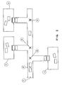
- this sorting station 7 is equipped in such a way as to be able to receive the cops coming from the winding/wrapping machine 1 and feed them automatically to a plurality of trimming machines 4,5,6, each one of them being capable of being fed by the apparatus located in the sorting station 7.
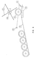
- This apparatus sends in turn a continuous sequence of cops to one of the trimming machines, as for instance the trimming machine 4, through an automatic handling means 8, which may for instance be a rocker-arm system (see Fig. 3), the arm of which picks the cops in sequence from the sorting station 7 and lays them down, one at a time, onto the buffering line of the trimming machine 4, or though for instance a conveyor belt.
- an automatic handling means 8 which may for instance be a rocker-arm system (see Fig. 3), the arm of which picks the cops in sequence from the sorting station 7 and lays them down, one at a time, onto the buffering line of the trimming machine 4, or though for instance a conveyor belt.
- both the apparatus in the station 7 and the handling means 8 automatically readjust so that they will no longer supply the trimming machine 4, but another trimming machine, such as for instance the trimming machine 5, according to a pre-programmed sequence through the automatic handling system 8 that in the meanwhile will have switched over to 8′.
- the just described process will be repeated once again, so that the whole feeding and handling equipment will readjust the next trimming machine, such as for instance the trimming machine 6, through the handling means 8 that in the meanwhile will have switched over to 8 ⁇ .
- a different embodiment of this invention can be devised by modifying the structure through which the cops are transferred from the sorting station 7 to the different loading stations.
- the device 18 is of course driven by a motor through coupling means consisting of a clutch-brake assembly actuated by a control device that will be described further on.
- a control device that will be described further on.
- the device according to the invention can be seen in its installed position, with the position sensors for detecting the presence of the moving objects duly fitted. These are typically formed by pairs of photoelectric cells 21 and 22 which are placed over the surface of the handling means 12 in correspondence of the device 18.
- the senor 21, 22 detects the presence of said cop there and, through a servomechanism, sends a proper command to the rotating wheel which immediately makes a turn by such an angle as to push with its closest surface the cop onto the loading ramp, as well as by such a further angle as to clear the space on the means 12 for the next cop to freely progress forward.
- FIG. 7 A preferred embodiment of said work surfaces 19 of the rotating device 18 is shown in Figure 7, where it can be seen that said surfaces are formed by a pair of substantially parallel arms 23 branching off outwards from the rotation axis of the device, the spacing between them being slightly narrower than the longitudinal size of the cop. In this way it is possible to further enhance the valuable result of appreciably reducing the total inertia of the rotating device 18.
- a further improvement in the operation of the rotating device 18 is achieved through the feature that will be explained below.
- said rotating device is actuated by a system of sensors capable of detecting the presence of the moving cops in a given position. It has also been said that said cops show up there in a random sequence, but at a high rate. It is therefore apparent that the device 18 undergoes a continuous sequence of start, rotation and stop commands that can be issued at very high rates of up to several hundreds of cops per minute, as explained above.
- a valuable improvement of the driving system consists in the use of a motor which runs continuously and which is connected to the rotating shaft of the device 18 through a so-called clutch-and-brake assembly of a type which is per se known in the art.
- a different embodiment of the rotating unloading device 18 as shown in the Figures 4, 5, 6 and 7 calls for the use of one or more belts, each one of them being installed on pairs of coplanar wheels that rotate in a synchronized way, but around two different, parallel axes.
- said belts will move with a synchronous and parallel motion at a constant distance from each other, in a much similar way as the tracks of a crawler tractor.
- At least one of said axes is mounted on a frame which is placed upon the handling means in correspondence of the loading ramp to the trimming machine, and is given such an orientation as to enable each belt to be arranged on a plane which is vertical and essentially transversal with respect to the moving direction of the cops on said handling or conveying means.
- Said frame is moving in an essentially vertical direction, so that, when it comes down, the belts will be caused to press against the cop that is then moving along on the handling means, and to push it aside owing to their synchronous, parallel motion. Immediately thereupon, the frame goes up in order to enable the next cop to move forward in the intended position, so that the just described procedure can be performed again.
- Figures 9 and 10 are cross-sectional views of particular details of Figure 8 to enable a better understanding of the latter.
- a ramp 34 is provided which is used to queue and feed, especially by gravity, the due sequence of cops 32 into the trimming machine 33.
- a stationary structure 35 is installed, to which following components are linked: the moving frame 36 which is hinged to said structure 35 at at least one pivot 313 with the possibility of moving around said hinging spot on a plane that is vertical and essentially transversal with respect to the orientation and the moving direction of the cops; the four wheels 37 being mounted on two distinct and parallel rotation axes, one of these axes being mounted on the structure 35 and the other one on the frame 36; the two belts 38 which are installed on the two pairs of wheels 37; the motor 39 which through traditional means and methods drives the wheels 37 that are shrink-fitted on the axis mounted on the stationary structure 35, and therefore also the belts 38; the motor 310 which, through the mechanical clutch-and-brake assembly 311, a possibly required reduction gear and a motion converting gear 312, is connected with the moving frame 36.
- the whole device in its installed arrangement can be seen, with its sensors for detecting the presence of the cops.
- These sensors consist typically in pairs of photoelectric cells 314a and 314b which are placed below the surface of the handling means 312 in correspondence of the position of the moving frame 36.
- the operational features of the device according to the invention will now become apparent to anyone skilled in the art.
- the semi-processed cops are loaded in sequence, at a variable rate and spacing, onto the handling means 312 which conveys them toward the station where the structure 35 is installed.
- a cop arrives in a position underneath the frame 36, a special command will actuate the mechanical clutch-and-brake assembly 311 of a per se known type, which therefore is actuated.
- Said assembly connects the motor 310, which is operating continuously, with the motion converting gear 312 which is mounted on the frame 36.
- Said gear 312 converts a rotary, fixed-axis motion into a reciprocating, rectilinear motion in a per se known way, such as for instance through a system of plurally lobed cams, a crank gear, etc.
- the frame 36 is given a reciprocating, essentially vertical motion being fast enough so as to comply with the most demanding output speed requirements, and moving in synchrony with the underlying cops on the handling means.
- the sensor (314a,314b) When the sensor (314a,314b) detects the presence of the new cop under the frame 36, it will send a special signal to the clutch-and-brake assembly 311 which will immediately become actuated for causing the frame 36 to come down by a stroke as it is required to perform the just described unloading procedure.
- a useful improvement of the device according to this invention can be seen in the fact that, if two or more cops are too close to each other or even touching each other when progressing along the handling means 31 (which thing could make it unpractical to unload them orderly from said means 31),it may become necessary to drive the frame 36 in such a way as to cause it to move upwards and allow said cops to pass by for eventually being collected for instance into a recovery container at the end of the line.
- a further sensor arrangement (315a,315b) can be devised before the position of the moving frame 36; said sensor, as connected to properly programmed logics, will then perform the above cited function of detecting the occurrence of irregular conditions along the handling means 31 and actuating the frame 36 for it to move upwards accordingly.
- the frame 36 may also be mounted on the stationary structure 35 in such a way as to have it moving vertically according to a displacement which is merely of translational motion.
- the hinge 313 would be omitted, while the two rotation axes 37 would be displaced jointly with the frame 36.
- the rotary motion to the wheels 37 can be transmitted by the motor 39 through one or more of several per se known techniques, such as for instance through belts or chains provided with automatic slack recovery stretcher, or through a system of Cardan joints, or through some kind of sliding gear, etc.
- the actuating device for stopping the cops is a device which is better illustrated in Figure 14. With particular reference to this Figure, it can be seen that it consists essentially of one or more moving obstacles 25 which can take different positions: one of these positions lies above the conveyor 12 in such a way as to have the obstacle 25 interfering with the outline generated by the moving cop 16 when this reaches the position where the shifting or unloading device 18 is located (Fig. 13). This moving obstacle can be displaced outside said cop outline by an appropriate control mechanism 24.
- One or more sensors for detecting the presence of objects as they are typically formed by pairs of photoelectric cells 29a,29b,30a,30b, are located in correspondence of the extreme positions of the loading ramp 17 used to feed the trimming machine 4.
- this device is as follows: the cops 16, which are already cut to length, move along the conveyor 12 in sequence, but separated from each other, until they reach an obstacle 25 which, acting as a kind of gate, is aimed at obstructing the passage of the cops in correspondence of the ramp 17, so that the other device, ie. the shifter 18, is able to push said cops out of the conveyor and feed them onto the loading ramp 17.
- Said command can be either a signal coming from a photoelectric cell 29a,29b which has detected an "overload” situation on the ramp 17 acting also as a buffer for feeding the machine 4, or any other signal or command coming from any other type of sensor.
- the shifter 18 When appropriate signals or commands are coming from the sensors 29a, 29b, 30a and 30,b, the shifter 18 is actuated and will shift all the cops out of the conveyor.
- the photoelectric cell arrangement 30a, 30b When the photoelectric cell arrangement 30a, 30b will then detect again an "empty" situation on the loading ramp 17, it sends a signal to the control mechanism 24 which moves the obstacle 25 to obstruct the path along which the cops are moving on the conveyor.
- An improvement in the way in which said obstacle or gate 25 operates derives from the fact that it may take the form of a rotating wheel provided with a plurality of essentially similar paddles. Each one of said paddles may constitute the necessary obstacle to the passage of the cops on their path along the conveyor, while between a paddle and the next one there is enough room for the cop to pass.
- the advantage deriving from this modified embodiment of the device according to the invention is that the wheel can be made to rotate at high speed and, therefore, is able to achieve its function of opening and closing the passage to the cops at a rate which is much faster than the one ensured by a single-gate device as described above.
- a further advantage of this invention is the following one: a drawback that can be experienced with a plant of a traditional type is the possibility that two or more cops are not duly spaced, but rather lie very close to each other or at an inadequate distance on the conveying means 12. In this case, they would both be stopped and, when the shifter 18 pushes the first cop toward the loading ramp, an undesirable, detrimental friction would occur between the two contiguous cops, which thing would not only damage both cops, but also cause the second cop to be pushed out of the conveying means 12 and to fall outside the loading ramp 17.
- the sensor system could be advantageously devised and arranged in such a way as to enable it to appropriately detect the presence of two successive cops being at too close a distance from each other or even touching each other on the conveying means 12 and, in such a case, send a signal to the gate 25 for it to open and allow said contiguous cops to pass by so that they will not be used in the on-going manufacturing process and, instead of this, will be collected in the appropriate container 28 which is provided at the end of the conveying line 12 for their due recovery.
- a third additional advantage of this invention derives from the fact that it is possible to automatically detect any irregular conditions occurring along the conveyor 12 and duly take care of it in a similarly automatic way.
Landscapes
- Mechanical Engineering (AREA)
- Engineering & Computer Science (AREA)
- Life Sciences & Earth Sciences (AREA)
- Forests & Forestry (AREA)
- Shaping Of Tube Ends By Bending Or Straightening (AREA)
- Replacing, Conveying, And Pick-Finding For Filamentary Materials (AREA)
- Making Paper Articles (AREA)
- Photoreceptors In Electrophotography (AREA)
- Bending Of Plates, Rods, And Pipes (AREA)
- Control Of Conveyors (AREA)
- Blow-Moulding Or Thermoforming Of Plastics Or The Like (AREA)
- Attitude Control For Articles On Conveyors (AREA)
- Preliminary Treatment Of Fibers (AREA)
- Discharge Of Articles From Conveyors (AREA)
- Special Conveying (AREA)
- Storing, Repeated Paying-Out, And Re-Storing Of Elongated Articles (AREA)
- Branching, Merging, And Special Transfer Between Conveyors (AREA)
- Turning (AREA)
- Grinding Of Cylindrical And Plane Surfaces (AREA)
- Treatment Of Fiber Materials (AREA)
Applications Claiming Priority (8)
| Application Number | Priority Date | Filing Date | Title |
|---|---|---|---|
| IT8803676A IT1226168B (it) | 1988-11-28 | 1988-11-28 | Procedimento per la fabbricazione di supporti cilindrici in cartone |
| IT367688 | 1988-11-28 | ||
| IT4574289 | 1989-06-16 | ||
| IT8945742A IT1235821B (it) | 1989-06-16 | 1989-06-16 | Dispositivo di deviazione di supporti da un trasportatore mobile |
| IT8945746A IT1235819B (it) | 1989-06-23 | 1989-06-23 | Dispositivo per il trasferimento automatico di supporti cilindrici su macchine rifinitrici. |
| IT4574689 | 1989-06-23 | ||
| IT4574989 | 1989-06-28 | ||
| IT8945749A IT1234277B (it) | 1989-06-28 | 1989-06-28 | Mezzi di espulsione di supporti cilindrici da un trasportatore mobile. |
Publications (3)
| Publication Number | Publication Date |
|---|---|
| EP0374489A2 true EP0374489A2 (de) | 1990-06-27 |
| EP0374489A3 EP0374489A3 (de) | 1991-09-18 |
| EP0374489B1 EP0374489B1 (de) | 1995-01-25 |
Family
ID=27452674
Family Applications (1)
| Application Number | Title | Priority Date | Filing Date |
|---|---|---|---|
| EP89121327A Expired - Lifetime EP0374489B1 (de) | 1988-11-28 | 1989-11-17 | Verfahren und Vorrichtung zur Herstellung von zylindrischen Unterstützungselementen in Beschneidevorrichtungen |
Country Status (12)
| Country | Link |
|---|---|
| US (1) | US5018336A (de) |
| EP (1) | EP0374489B1 (de) |
| JP (1) | JPH02215665A (de) |
| KR (1) | KR0163416B1 (de) |
| AT (1) | ATE117617T1 (de) |
| CA (1) | CA2003930A1 (de) |
| DE (1) | DE68920848T2 (de) |
| DK (1) | DK596789A (de) |
| ES (1) | ES2070161T3 (de) |
| GR (1) | GR3015236T3 (de) |
| IL (1) | IL92379A0 (de) |
| PT (1) | PT92424B (de) |
Families Citing this family (7)
| Publication number | Priority date | Publication date | Assignee | Title |
|---|---|---|---|---|
| EP1100722B1 (de) * | 1998-07-24 | 2003-05-28 | Pulsar S.r.l. | Vorrichtung und verfahren zum fördern von gegenständen in form zylindrischer rollen |
| IT1320899B1 (it) * | 2000-02-25 | 2003-12-10 | Pulsar Srl | Impianto per il trattamento di articoli e apparato di convogliamentodegli articoli utilizzabile in detto impianto. |
| CA2302095C (en) * | 2000-03-24 | 2005-06-14 | Gemofor Inc. | A lumber transfer system |
| US6612418B2 (en) * | 2002-01-14 | 2003-09-02 | General Mills, Inc. | System for use in an assembly line |
| US7389622B2 (en) * | 2003-01-13 | 2008-06-24 | General Mills, Inc. | System for use in an assembly line |
| US7584589B2 (en) * | 2007-03-09 | 2009-09-08 | Georgia-Pacific Consumer Products Lp | Robotic multi-product case-packing system |
| DE102021123023A1 (de) * | 2021-09-06 | 2023-03-09 | Wipotec Gmbh | Sortiervorrichtung |
Family Cites Families (13)
| Publication number | Priority date | Publication date | Assignee | Title |
|---|---|---|---|---|
| DE2354303A1 (de) * | 1973-10-26 | 1974-11-07 | Dieter Bruhm | Entnahmevorrichtung fuer foerderband |
| IT1004478B (it) * | 1974-04-18 | 1976-07-10 | Pennwalt Corp | Perfezionamento nei sistemi di manipolazione di prodotti ortofrutticoli |
| US4057138A (en) * | 1976-02-05 | 1977-11-08 | Wisconsin Bridge & Iron Co. | Apparatus for routing logs |
| US4021992A (en) * | 1976-07-06 | 1977-05-10 | J. I. Case Company | In-line system of packaging, securing, and weighing |
| DE2638280C3 (de) * | 1976-08-25 | 1981-02-26 | Nuetro Patentverwertungs- U. Maschinenhandels-Gmbh, 8500 Nuernberg | Vorrichtung zum Herstellen eines mehrreihigen Gebindes aus Behältern, wie Flaschen, Gläsern o.dgl |
| US4121403A (en) * | 1977-09-06 | 1978-10-24 | Pitney-Bowes, Inc. | Flat mail sorter and loader |
| US4193489A (en) * | 1977-11-14 | 1980-03-18 | Rockwell International Corporation | Exit conveyor system for newspaper mail room |
| CH621981A5 (de) * | 1977-12-29 | 1981-03-13 | Sig Schweiz Industrieges | |
| US4525978A (en) * | 1981-09-17 | 1985-07-02 | Mitsubishi Jukogyo Kabushiki Kaisha | Sterilizing system for filled and sealed articles |
| DE3243417A1 (de) * | 1981-12-07 | 1983-06-09 | Maschinenfabrik Schweiter AG, 8810 Horgen | Verfahren und vorrichtung zur positionierung und zur uebergabe von spinnkopsen |
| US4628665A (en) * | 1985-03-01 | 1986-12-16 | Mobil Oil Corporation | Modular indexing table for a box loading system |
| FR2596370B1 (fr) * | 1986-03-26 | 1991-03-22 | Herve Fils Sa | Convoyeur a courroies plates pour le transport d'objets legers |
| US4821865A (en) * | 1987-05-12 | 1989-04-18 | Topy Kogyo Kabushiki Kaisha | Work delivering apparatus |
-
1989
- 1989-11-15 KR KR1019890016536A patent/KR0163416B1/ko not_active Expired - Fee Related
- 1989-11-17 ES ES89121327T patent/ES2070161T3/es not_active Expired - Lifetime
- 1989-11-17 DE DE68920848T patent/DE68920848T2/de not_active Expired - Fee Related
- 1989-11-17 AT AT89121327T patent/ATE117617T1/de not_active IP Right Cessation
- 1989-11-17 EP EP89121327A patent/EP0374489B1/de not_active Expired - Lifetime
- 1989-11-21 IL IL92379A patent/IL92379A0/xx unknown
- 1989-11-27 DK DK596789A patent/DK596789A/da not_active Application Discontinuation
- 1989-11-27 JP JP1307404A patent/JPH02215665A/ja active Pending
- 1989-11-27 CA CA002003930A patent/CA2003930A1/en not_active Abandoned
- 1989-11-28 PT PT92424A patent/PT92424B/pt not_active IP Right Cessation
- 1989-11-28 US US07/442,982 patent/US5018336A/en not_active Expired - Lifetime
-
1995
- 1995-03-01 GR GR950400445T patent/GR3015236T3/el unknown
Also Published As
| Publication number | Publication date |
|---|---|
| DE68920848D1 (de) | 1995-03-09 |
| ATE117617T1 (de) | 1995-02-15 |
| DK596789A (da) | 1990-05-29 |
| IL92379A0 (en) | 1990-07-26 |
| PT92424B (pt) | 1995-08-09 |
| KR900007589A (ko) | 1990-06-01 |
| CA2003930A1 (en) | 1990-05-28 |
| EP0374489A3 (de) | 1991-09-18 |
| KR0163416B1 (ko) | 1998-12-01 |
| GR3015236T3 (en) | 1995-06-30 |
| EP0374489B1 (de) | 1995-01-25 |
| PT92424A (pt) | 1990-05-31 |
| ES2070161T3 (es) | 1995-06-01 |
| JPH02215665A (ja) | 1990-08-28 |
| DK596789D0 (da) | 1989-11-27 |
| DE68920848T2 (de) | 1995-09-07 |
| US5018336A (en) | 1991-05-28 |
Similar Documents
| Publication | Publication Date | Title |
|---|---|---|
| US3370549A (en) | Transfer apparatus | |
| US5115625A (en) | In-line bottom loading case packer | |
| EP0124177B1 (de) | Vorrichtung für den Transfer einer Reihe von Gegenständen von einem Bandförderer zu einem transversal laufenden Bandförderer | |
| EP2697122B1 (de) | Einwickelmaschine und einwickelverfahren | |
| US6550608B1 (en) | Carton feeding system for packaging machine | |
| CA1187118A (en) | Method and device to continuously form packets of folded boxes to be processed in a machine | |
| US5400894A (en) | Production line accumulator | |
| GB2296228A (en) | Method and apparatus for automatically conveying workpieces | |
| US3932919A (en) | Improved gripper return means for a machine for simultaneously biaxially stretching thermoplastic film | |
| EP0374489A2 (de) | Verfahren und Vorrichtung zur Herstellung von zylindrischen Unterstützungselementen in Beschneidevorrichtungen | |
| JPS5938131B2 (ja) | ふた付き袋を分離して充填機に送る装置 | |
| CN115959421A (zh) | 运输装置 | |
| CA2143547A1 (en) | Plywood layup system | |
| EP0792806B1 (de) | Vorrichtung zum Fördern von Paketen | |
| US5013213A (en) | Automatic denesting machine | |
| US3488693A (en) | Bag-making machine | |
| WO2011151774A1 (en) | Apparatus and method for packaging stacks of folded tissue products and the like with a plastic film | |
| US5776292A (en) | Plywood lay-up system | |
| US4022091A (en) | Machine for dressing continuous web materials in stretched condition on a plurality of frames | |
| US6554124B2 (en) | Equipment for feeding product groups to a conveyor for their packaging | |
| US4884675A (en) | Linking process and linking device between a fabrication machine for envelopes and a conditioning machine | |
| IE66700B1 (en) | Process and apparatus for manufacturing cylindrical supports of trimming machines | |
| US7536842B2 (en) | Machine and a method for filling box-like containers with articles arranged side by side and vertically | |
| JPH09278165A (ja) | 整列装置 | |
| JPH0455935B2 (de) |
Legal Events
| Date | Code | Title | Description |
|---|---|---|---|
| PUAI | Public reference made under article 153(3) epc to a published international application that has entered the european phase |
Free format text: ORIGINAL CODE: 0009012 |
|
| AK | Designated contracting states |
Kind code of ref document: A2 Designated state(s): AT BE CH DE ES FR GB GR LI LU NL SE |
|
| PUAL | Search report despatched |
Free format text: ORIGINAL CODE: 0009013 |
|
| AK | Designated contracting states |
Kind code of ref document: A3 Designated state(s): AT BE CH DE ES FR GB GR LI LU NL SE |
|
| 17P | Request for examination filed |
Effective date: 19911014 |
|
| 17Q | First examination report despatched |
Effective date: 19920807 |
|
| GRAA | (expected) grant |
Free format text: ORIGINAL CODE: 0009210 |
|
| AK | Designated contracting states |
Kind code of ref document: B1 Designated state(s): AT BE CH DE ES FR GB GR LI LU NL SE |
|
| REF | Corresponds to: |
Ref document number: 117617 Country of ref document: AT Date of ref document: 19950215 Kind code of ref document: T |
|
| REF | Corresponds to: |
Ref document number: 68920848 Country of ref document: DE Date of ref document: 19950309 |
|
| PG25 | Lapsed in a contracting state [announced via postgrant information from national office to epo] |
Ref country code: SE Effective date: 19950425 |
|
| ET | Fr: translation filed | ||
| REG | Reference to a national code |
Ref country code: GR Ref legal event code: FG4A Free format text: 3015236 |
|
| REG | Reference to a national code |
Ref country code: ES Ref legal event code: FG2A Ref document number: 2070161 Country of ref document: ES Kind code of ref document: T3 |
|
| PLBE | No opposition filed within time limit |
Free format text: ORIGINAL CODE: 0009261 |
|
| STAA | Information on the status of an ep patent application or granted ep patent |
Free format text: STATUS: NO OPPOSITION FILED WITHIN TIME LIMIT |
|
| 26N | No opposition filed | ||
| REG | Reference to a national code |
Ref country code: GB Ref legal event code: IF02 |
|
| PGFP | Annual fee paid to national office [announced via postgrant information from national office to epo] |
Ref country code: AT Payment date: 20041007 Year of fee payment: 16 |
|
| PG25 | Lapsed in a contracting state [announced via postgrant information from national office to epo] |
Ref country code: AT Free format text: LAPSE BECAUSE OF NON-PAYMENT OF DUE FEES Effective date: 20051117 |
|
| PGFP | Annual fee paid to national office [announced via postgrant information from national office to epo] |
Ref country code: NL Payment date: 20061013 Year of fee payment: 18 |
|
| PGFP | Annual fee paid to national office [announced via postgrant information from national office to epo] |
Ref country code: GB Payment date: 20061016 Year of fee payment: 18 |
|
| PGFP | Annual fee paid to national office [announced via postgrant information from national office to epo] |
Ref country code: CH Payment date: 20061017 Year of fee payment: 18 |
|
| PGFP | Annual fee paid to national office [announced via postgrant information from national office to epo] |
Ref country code: GR Payment date: 20061020 Year of fee payment: 18 |
|
| PGFP | Annual fee paid to national office [announced via postgrant information from national office to epo] |
Ref country code: DE Payment date: 20061025 Year of fee payment: 18 |
|
| PGFP | Annual fee paid to national office [announced via postgrant information from national office to epo] |
Ref country code: BE Payment date: 20061108 Year of fee payment: 18 |
|
| PGFP | Annual fee paid to national office [announced via postgrant information from national office to epo] |
Ref country code: LU Payment date: 20061120 Year of fee payment: 18 |
|
| PGFP | Annual fee paid to national office [announced via postgrant information from national office to epo] |
Ref country code: ES Payment date: 20061121 Year of fee payment: 18 |
|
| BERE | Be: lapsed |
Owner name: *BASTIANELLO UMBERTO Effective date: 20071130 |
|
| GBPC | Gb: european patent ceased through non-payment of renewal fee |
Effective date: 20071117 |
|
| PG25 | Lapsed in a contracting state [announced via postgrant information from national office to epo] |
Ref country code: CH Free format text: LAPSE BECAUSE OF NON-PAYMENT OF DUE FEES Effective date: 20071130 Ref country code: LI Free format text: LAPSE BECAUSE OF NON-PAYMENT OF DUE FEES Effective date: 20071130 |
|
| REG | Reference to a national code |
Ref country code: CH Ref legal event code: PL |
|
| NLV4 | Nl: lapsed or anulled due to non-payment of the annual fee |
Effective date: 20080601 |
|
| PG25 | Lapsed in a contracting state [announced via postgrant information from national office to epo] |
Ref country code: BE Free format text: LAPSE BECAUSE OF NON-PAYMENT OF DUE FEES Effective date: 20071130 |
|
| PG25 | Lapsed in a contracting state [announced via postgrant information from national office to epo] |
Ref country code: DE Free format text: LAPSE BECAUSE OF NON-PAYMENT OF DUE FEES Effective date: 20080603 Ref country code: NL Free format text: LAPSE BECAUSE OF NON-PAYMENT OF DUE FEES Effective date: 20080601 |
|
| PGFP | Annual fee paid to national office [announced via postgrant information from national office to epo] |
Ref country code: FR Payment date: 20061002 Year of fee payment: 18 |
|
| REG | Reference to a national code |
Ref country code: FR Ref legal event code: ST Effective date: 20080930 |
|
| PG25 | Lapsed in a contracting state [announced via postgrant information from national office to epo] |
Ref country code: GB Free format text: LAPSE BECAUSE OF NON-PAYMENT OF DUE FEES Effective date: 20071117 |
|
| REG | Reference to a national code |
Ref country code: ES Ref legal event code: FD2A Effective date: 20071119 |
|
| PG25 | Lapsed in a contracting state [announced via postgrant information from national office to epo] |
Ref country code: FR Free format text: LAPSE BECAUSE OF NON-PAYMENT OF DUE FEES Effective date: 20071130 Ref country code: ES Free format text: LAPSE BECAUSE OF NON-PAYMENT OF DUE FEES Effective date: 20071119 |
|
| PG25 | Lapsed in a contracting state [announced via postgrant information from national office to epo] |
Ref country code: GR Free format text: LAPSE BECAUSE OF NON-PAYMENT OF DUE FEES Effective date: 20080605 |
|
| PG25 | Lapsed in a contracting state [announced via postgrant information from national office to epo] |
Ref country code: LU Free format text: LAPSE BECAUSE OF NON-PAYMENT OF DUE FEES Effective date: 20071117 |