EP0373608A2 - Microwave heating apparatus - Google Patents
Microwave heating apparatus Download PDFInfo
- Publication number
- EP0373608A2 EP0373608A2 EP89122965A EP89122965A EP0373608A2 EP 0373608 A2 EP0373608 A2 EP 0373608A2 EP 89122965 A EP89122965 A EP 89122965A EP 89122965 A EP89122965 A EP 89122965A EP 0373608 A2 EP0373608 A2 EP 0373608A2
- Authority
- EP
- European Patent Office
- Prior art keywords
- power feeding
- waveguide
- heating chamber
- heating apparatus
- microwave heating
- Prior art date
- Legal status (The legal status is an assumption and is not a legal conclusion. Google has not performed a legal analysis and makes no representation as to the accuracy of the status listed.)
- Granted
Links
Images


Classifications
-
- H—ELECTRICITY
- H05—ELECTRIC TECHNIQUES NOT OTHERWISE PROVIDED FOR
- H05B—ELECTRIC HEATING; ELECTRIC LIGHT SOURCES NOT OTHERWISE PROVIDED FOR; CIRCUIT ARRANGEMENTS FOR ELECTRIC LIGHT SOURCES, IN GENERAL
- H05B6/00—Heating by electric, magnetic or electromagnetic fields
- H05B6/64—Heating using microwaves
- H05B6/6408—Supports or covers specially adapted for use in microwave heating apparatus
- H05B6/6411—Supports or covers specially adapted for use in microwave heating apparatus the supports being rotated
-
- H—ELECTRICITY
- H05—ELECTRIC TECHNIQUES NOT OTHERWISE PROVIDED FOR
- H05B—ELECTRIC HEATING; ELECTRIC LIGHT SOURCES NOT OTHERWISE PROVIDED FOR; CIRCUIT ARRANGEMENTS FOR ELECTRIC LIGHT SOURCES, IN GENERAL
- H05B6/00—Heating by electric, magnetic or electromagnetic fields
- H05B6/64—Heating using microwaves
- H05B6/6402—Aspects relating to the microwave cavity
-
- Y—GENERAL TAGGING OF NEW TECHNOLOGICAL DEVELOPMENTS; GENERAL TAGGING OF CROSS-SECTIONAL TECHNOLOGIES SPANNING OVER SEVERAL SECTIONS OF THE IPC; TECHNICAL SUBJECTS COVERED BY FORMER USPC CROSS-REFERENCE ART COLLECTIONS [XRACs] AND DIGESTS
- Y10—TECHNICAL SUBJECTS COVERED BY FORMER USPC
- Y10T—TECHNICAL SUBJECTS COVERED BY FORMER US CLASSIFICATION
- Y10T29/00—Metal working
- Y10T29/49—Method of mechanical manufacture
- Y10T29/49002—Electrical device making
Definitions
- the present invention relates to a microwave heating apparatus such as an electronic oven. More particularly, it relates to an improvement in the shape of a waveguide having a plurality of power feeding ports.
- FIGS 31 and 32 are respectively longitudinal cross-sectional views in schematic forms of an electronic oven which utilizes a conventional microwave heating apparatus. Description will be made with reference to Figures 31 and 32.
- a reference numeral 1 designates a heating chamber
- a numeral 2 designates a turn table positioned at the lower portion of the heating chamber 1 and adapted to receive thereon a material to be heated 6
- a numeral 3 designates a magnetron for generating microwaves
- a numeral 7 designates an antenna for emitting the microwaves
- a numeral 4 designates a waveguide which is attached to the outer wall of the ceiling of the heating chamber 1 and guides the microwaves emitted from the magnetron 3 to a power feeding port formed in the ceiling of the heating chamber 1.
- the conventional electronic oven as shown in Figure 31 is so adapted that the material to be heated 6 (hereinbelow, referred to as a heating material) is placed on the turn table 2, and when a door is closed to actuate a power switch (not shown), the turn table 2 is started to rotate, and at the same time, microwaves are emitted from the antenna 7 of the magnetron 3.
- the microwaves are supplied to the heating chamber 1 via the waveguide 4 and the power feeding port 5 to thereby heat the heating material 6.
- Figure 32 shows another conventional technique, wherein a power feeding port 5 is formed at the upper portion of a side wall of the heating chamber 1. Microwaves are supplied into the heating chamber 1 through the power feeding port 5. A waveguide 4 attached to the outer surface of the side wall of the heating chamber 1. The function of the apparatus as shown in Figure 32 is the same as that in Figure 31.
- the microwaves can not be supplied uniformly to the heating material 6 as shown in Figures 31 and 32 to thereby often cause uneven heating to the heating material. Further, it takes much time to heat the heating material 6 depending on the position of the heating material, and much power is consumed.
- Figure 33 is a longitudinal cross-sectional view of a conventional microwave heating apparatus having power feeding ports formed in the ceiling of the heating chamber, which is described in, for instance, Japanese Examined Utility Model Publication 15589/1986.
- Figure 34 is a longitudinal cross-sectional view of a conventional microwave heating apparatus having power feeding ports in a side surface of the heating chamber.
- a numeral 1 designates a heating chamber
- a numeral 8 designates a waveguide attached to the top surface of the heating chamber 1 so that an end of the waveguide projects from the right side portion of the top surface
- a numeral 9 designates three power feeding ports formed in the top surface of the heating chamber 1 so as to communicate the waveguide 8 with the heating chamber 1
- a numeral 3 designates a magnetron as a microwave oscillating apparatus which is connected to the lower end of the projecting portion of the waveguide 8 and has an antenna 7 extending in the waveguide 8.
- a waveguide 10 is provided at a side surface of the heating chamber 1, and two power feeding ports are formed at the side surface of the heating chamber 1 so as to communicate the waveguide 10 with the heating chamber 1.
- a wavelength of radiowaves oscillated from the antenna 7 is ⁇ g.
- the distance from the center of the antenna 7 to the surface of the waveguide 8 facing oppositely the surface where the power feeding ports are formed is called a back plunger which has a wavelength of ⁇ g/4, and it is usually determined to be 18.6 mm - 22 mm.
- the microwave heating apparatus having more than two power feeding ports with the back plunger is disclosed in addition to the above-mentioned conventional apparatus, in publications such as Japanese Examined Patent Publication 37504/1987, Japanese Examined Patent Publication 30077/1985, Japanese Examined Utility Model Publication 22080/1987, Japanese Examined Utility Model Publication 31999/1987, Japanese Examined Utility Model Publication 30798/1987, Japanese Examined Utility Model Publication 11916/1986, Japanese Examined Utility Model Publication 35988/1985, Japanese Examined Utility Model Publication 35991/1985 and so on.
- microwaves oscillated from the antenna 7 of the magnetron 3 are propagated toward the heating chamber 1 by the back plunger provided in the waveguide 8 or 10 and are introduced into the heating chamber 1 through the power feeding ports 6, whereby a material to be cooked placed in the heating chamber 1 is heated.
- the shape of the waveguide 8 or 10 was inevitably complicated by satisfying both requirements that the back plunger has to be provided and a plurality of power feeding ports 9 or 11 have to be provided at desired positions.
- the back plunger is assured by projecting an end of the waveguide 8 from an end of the heating chamber, by connecting the magnetron 3 at the lower portion of the projecting part, and by inserting the antenna 7.
- the back plunger is assured by projecting the central portion of the waveguide 10 in the lateral direction, by connecting the magnetron 3 to the lower portion of the projecting part, and by inserting the antenna 7.
- the magnetron 3 and its connecting portion were unevenly projected with respect to the heating chamber 1. Accordingly, there arose problems that the structure of the waveguide 8 or 10 was complicated, the number of machining steps was increased, hence, the manufacturing cost became high, a freedom in determining the position of structural elements was limited, and the size of a microwave heating apparatus main body became large.
- a waveguide 8 is attached to the top surface of the heating chamber so as to extend from an end to the other end, but so as not to project from the heating chamber 1, power feeding ports 14 are formed at the central portion and an end portion so as to communicate the waveguide 8 with the heating chamber 1, and an antenna 7 for a magnetron 3 is arranged at a position apart from the end of the waveguide 8 by a wavelength of ⁇ g/4.
- the length of the waveguide 8 is inevitably large and it is impossible to form the power feeding ports at both end portions. Further, it is difficult to reduce uneven heating because the plural power feeding ports are formed.
- a microwave heating apparatus which comprises a microwave heating apparatus main body, a heating chamber provided in the microwave heating apparatus main body, a waveguide member for providing a waveguide projecting substantially uniformly along a wall of the heating chamber, a plurality of power feeding parts for communicating the inside of the waveguide with the heating chamber, and a microwave oscillating antenna arranged along the surface of the waveguide facing the segment between the power feeding parts.
- a microwave heating apparatus which comprises a microwave heating apparatus main body, a heating chamber provided in the microwave heating apparatus main body, a waveguide member connected to a wall of the heating chamber and forming a waveguide having a substantially rectangular body, power feeding parts formed at both end portions in the longitudinal direction of the waveguide, and a microwave oscillating antenna arranged along the surface of the waveguide facing the portion between the power feeding parts.
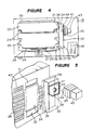
- FIGS 1 through 10 show a first embodiment of the microwave heating apparatus of the present invention.
- a reference numeral 15 designates a microwave heating apparatus main body as a main part of an electronic oven
- a numeral 16 designates a U-shaped casing having air discharge ports 17 at a side surface
- a numeral 18 designates a rear plate in which air intake ports 19 are formed at the right side when viewed from the front of the electronic oven and air discharge ports 20 at the central portion
- a numeral 21 designates a vertically opening type door pivotally supported at the lower edge portion of the front part of the electronic oven
- a numeral 22 designates a heating chamber formed in the electronic oven 15 to have a capacity defined by a width of 343 mm, a depth of 340 mm and a height of 208 mm so that it communicate with the atmosphere by opening the vertically opening door
- a numeral 23 designates an operating panel provided at the right side of the vertically opening door 21
- a numeral 24 designates dish receiving racks which are attached
- each of the dish receiving racks are formed in a generally rounded -like shape in vertical cross section.
- the intermediate portion of each of the dish receiving racks at the upper and middle stages is so formed that the edge portion of the -like portion is vertically cut, and the intermediate portion of the dish receiving racks at the lower stage has no cut portion.
- the shape of the intermediate portion of the dish receiving racks 24 at the upper and middle stages is called a recess 25.
- a numeral 26 designates a turn table to receive thereon a material to be cooked (hereinafter, referred to as a cooking material).
- the turn table is put on a rotating plate 28 which is placed in the heating chamber 22 and has the lower surface connected to the shaft of a driving motor 27 which is provided at the central portion of the bottom of the microwave heating apparatus main body, i.e. below the heating chamber 22.
- a numeral 29 designates a lower heater consisting of a mica heater attached to the substantially entire region of the outer bottom surface of the heating chamber 22, and a numeral 30 designates an upper heater consisting of a mica heater placed on the substantially entire surface of the outer top surface of the heating chamber 22.
- a numeral 31 designates an upper feeding port having a dimension of 15 mm long and 82 mm wide which is formed in the right side wall of the heating chamber 22 and at a position having its center which is 16 mm lower than the upper edge of the heating chamber 22 and 195 mm deeper than the front edge of the heating chamber 22.
- a numeral 32 designates a lower feeding port having a dimension of 35 mm long and 82 mm wide which is formed in the same right side wall and at a portion having its center which is 173.5 mm lower than the upper edge and 195 mm deeper than the front edge of the heating chamber 22.
- a numeral 33 designates a waveguide as a waveguide member attached to an outer wall of the heating chamber 22 by spot welding so as to communicate the upper and lower feeding ports 31, 32 with the heating chamber 22. The outer configuration of the waveguide is in a substantially rectangular prism.
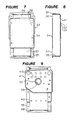
- the waveguide 33 is basically constituted by three structural elements as shown in Figure 5. This will be described in detail.
- a numeral 34 designates a guide plate having a dimension of 130 mm long, 110 mm wide and 0.6 mm thick which covers an uneven surface formed in the outer side wall of the heating chamber, the uneven surface being resulted from forming the dish receiving racks 24 in the heating chamber 22 at the position between the upper and lower power feeding ports 31, 32.
- a numeral 35 designates a guide box of a rectangular prism body having an open surface and having a capacity of 180 mm long x 80 mm wide x 35 mm high. The central portion of the open surface is covered by the guide plate 34 to thereby form an upper opening 36 and a lower opening 37 which respectively face the upper and lower power feeding ports 31, 32.
- the guide box 35 has a flange 38 of about 10 mm projecting from the outer circumference of the open surface. Both sides of the flange portion are connected to the outer side wall of the heating chamber 22 together with the guide plate 34 in an overlapping state, and the other portion of the flange 38 is directly connected to the outer wall of the heating chamber 22 by spot-welding.
- the upper and lower power feeding ports 31, 32 are communicated with each other in the guide box 35 through the upper and lower openings 36, 37 formed in the guide box 15.
- a numeral 39 designates a round opening having a diameter of 22 mm whose center is located at a point which is 55 mm lower than the upper surface of the guide box 35 and at the center in the traversing direction of the surface of the guide box 35 which opposes the upper and lower openings 36, 37.
- An annular raised portion having a width of 3.5 mm and a height of 1.6 mm is formed around the round opening.
- the center of the round opening 39 is apart from the center of the upper opening 36 by 46.5 mm and is apart from the center of the lower opening 37 by 137.5 mm.
- openings 40 for receiving terminals are formed in the opposing surface of the guide box 35 in order to connect the upper and lower end portions of the guide plate 34 to the outer side wall of the heating chamber 22 by spot-welding.
- Four openings 40 are arranged in line with intervals of 22 mm at positions 35.5 mm higher than the center of the round opening 39, and four openings are arranged in line with intervals of 22 mm at positions 85.5 mm lower than the round opening 39.
- a numeral 41 designates a magnetron supporting plate having a dimension of 100 mm long and 122 mm wide which is spot-welded around the round opening 39 of the guide box 35, and has an opening 42 having a diameter of 31 mm which opens facing the round opening 39.
- the waveguide 33 comprises the guide plate 34, the guide box 35 and the magnetron supporting plate 41.
- a numeral 43 designates a magnetron as a microwave oscillating device which is secured to an element attached to the guide box 35 through the magnetron supporting plate 41 by means of three screws.and two pawls. Further, an antenna 44 is inserted in the openings 39, 42.
- a numeral 45 designates a plurality of cooling fins formed on the entire circumference of the middle portion of the magnetron 43.
- a numeral 46 designates a duct having an end which is opened to the left side surfaces of the cooling fins 45 and the other end which is opened to a plurality of apertures 47 perforated at the upper part of the outer side wall of the heating chamber 22 to face the vertically opening door 21.
- a numeral 48 designates a high frequency transformer placed just below the magnetron 43.
- a numeral 49 designate a blower positioned above and behind the magnetron 43. The blower is so supported that the blades of the blower face an opening of a fan fitting plate 50 which is so constructed that round opening is formed in a upright rectangular flat plate.
- a packing 51 for anti-leakage is bonded to the circumferential surface of the fan fitting plate 50 so as to be in contact with the inner wall of the casing 16 for the electronic oven 15.
- a numeral 52 designates a high voltage relay located just below the blower 49
- a numeral 53 designates a high voltage capacitor located behind the high voltage relay 52
- a numeral 54 designates electronic elements comprising a plurality of substrates which are provided behind the operating panel
- a numeral 55 designates a thermostat attached to the magnetron 43.
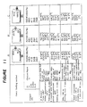
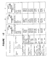
- a microwave heating apparatus having the same construction as described above was used.
- a microwave heating apparatus used for a power feeding method B the size of opening of the upper power feeding port 31 is same as that of the lower power feeding port 32.
- a microwave heating apparatus having a single power feeding port which is the same as the conventional apparatus was used.
- the wall surface attached with the waveguide 33 can be reinforced due to the fact that the waveguide 33 uniformly faces the wall surface, hence it can uniformly receive an external force, in comparison with the conventional microwave heating apparatus in which an end of the waveguide projects from the wall surface of the microwave heating main body.
- a trouble such as dropping of a dish which is caused by the spreading of the distance between a pair of dish receiving racks by the expansion of the heating chamber 22 when an electric oven is used, can be prevented.
- An air layer in the waveguide 33 functions as an insulating material against the wall surface to which the waveguide 33 is connected.
- the microwave heating apparatus is so constructed that the lower power feeding port 32 has a larger opening than the upper power feeding port 31, and the antenna for oscillating microwaves faces to the upper power feeding port 31.
- the position and the shape of the waveguide 33, the positions of the power feeding ports, the surface area and the shape of the opening for the ports, the position of the antenna and so on may be determined as desired depending on the shape and the volume of the heating chamber 22.
- the optimum heating can be given to a heating material by changing a quantity of power fed through each of the power feeding ports.
- Figures 13 and 14 are respectively plane view and a longitudinal cross-sectional view schematically shown of a second embodiment of the microwave heating apparatus.
- the same reference numerals as in Figures 1 through 10 designate the same or corresponding parts, and therefore, description of these parts is omitted.
- An upper power feeding port 31 is formed at the upper part of a side wall of the heating chamber 22 and a lower power feeding port 32 is formed at a lower part of it.
- a waveguide 33 with a magnetron 43 is attached to the outer surface of a side wall of the heating chamber 22 so as to be communicated with the upper and lower power feeding ports 31, 32.
- the lower power feeding port 32 is provided at a place lower than a material to be heated 6.
- the dimension in the vertical direction (in the direction of height) of the upper power feeding feeding port 31 is 15 mm and the dimension of the lower power feeding port 32 is 35 mm, which is greater than the upper power feeding port 31.
- microwaves are fed in the heating chamber 22 through the upper and lower power feeding ports 31, 32, whereby uneven heating to the material to be heated 6 can be reduced and a time of heating can be shortened.
- the microwaves are supplied to the upper and lower portion of the material 6, whereby a time of heating can be further shortened.
- Figures 15 and 16 are respectively diagrams showing a third embodiment of the microwave heating apparatus according to the present invention.
- the upper and lower power feeding ports 31, 32 are respectively formed at corner portions (in the direction of depth) of a side wall of the heating chamber 22, and a waveguide 33 with a magnetron 43 is fixed to the corner portion of the outer side of the side wall of the heating chamber 22.
- a small bottle or a cup containing a water-rich material 6 such as "sake” (Japanese wine), milk or the like can be directly placed at the corner portion of the bottom plate of the heating chamber which does not interfere with the rotation of the turn table 26. Then, the material 6 to be heated can be heated from the upper and side directions to thereby reduce the possibility of uneven heating, and shorten a time of heating. In this case, it is possible to stop the rotation of the turn table 26 if necessary.
- a water-rich material 6 such as "sake” (Japanese wine), milk or the like
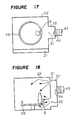
- FIGS 17 and 18 show a fourth embodiment of the microwave heating apparatus of the present invention.
- an upper feeding port 31 is formed at the upper portion of a side wall of the heating chamber, and a lower power feeding port 32 is formed in the side wall and near the turn table 26.
- a waveguide 33 is attached to the outer surface of the side wall of the heating chamber 22.
- a water-rich material 6 to be heated can be placed on the turn table 26 so as to be close to the lower power feeding port 32.
- microwaves are supplied from the upper and side directions to the material 6, whereby a possibility of uneven heating can be reduced and the material can be heated for a short time.
- FIGS 19 and 20 show a fifth embodiment of the present invention.
- an upper power feeding port 31 is formed at an upper corner portion in a side wall of the heating chamber 22, and a lower feeding port 32 is formed in the bottom surface of the heating chamber 22.
- a waveguide 33 is attached to the heating chamber so as to cover the upper and lower power feeding ports 31, 32.
- the upper power feeding port is formed at the upper portion of a side wall of the heating chamber, and a lower power feeding port is formed at the bottom surface or a lower portion of the side wall of the heating chamber.
- the upper power feeding port may be formed in the ceiling of the heating chamber.
- the guide box 35 of the waveguide 33 is attached to the heating chamber 22 so that the upper and lower surfaces of the guide box 35 are respectively perpendicular to the side wall of the heating chamber 22.
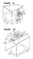
- the upper and lower surfaces of the guide box 35 may be inclined so that a skirt portion is formed at the surface for mounting the magnetron 43 of the guide box 35 to the surface which is in contact with the outer surface of the heating chamber 22 as shown in Figure 21.
- the waveguide 33 can be formed by drawing operations. Accordingly, the manufacturing cost can be reduced because only stamping operations are needed for manufacturing the waveguide. The same effect can be obtained by forming the upper and lower surfaces in a spherical form.
- a tapered portion may be formed at a side surface of the waveguide 33.
- the waveguide 33 having a substantially rectangular prism includes embodiments having the above-mentioned tapered surface or spherical surface.
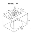
- the waveguide 33 is provided at the outer wall of the heating chamber 22. However, it may be formed in or be attached to the inside of the heating chamber 22 as shown in Figures 22 through 25. With such construction, it seems that the magnetron 43 is directly attached to the heating chamber 22 in appearance. Accordingly, other structural elements can be arranged at suitable positions, and it is possible to reduce the size of the microwave heating apparatus main body 15.
- step portions 56 are formed at both sides of the upper surface of the heating chamber 22, and a flat plate 58 in which two power feeding ports 57 are formed is mounted on the heating chamber 25 so as to bridge the step portions 56.
- the manufacturing cost can be greatly reduced.
- the central portion in the shorter side of a rectangular flat plate is stamped to form a recess, and both side portions in the shorter side of the rectangular flat plate are connected to the top surface of the heating chamber 22 by spot-welding, so that power feeding ports 59 are formed at both ends in the longitudinal direction of the heating chamber.
- formed waveguide 33 reduces the manufacturing cost.
- FIG. 26 shows another embodiment of the microwave heating apparatus of the present invention.
- an intermediate power feeding port 60 is formed between upper and lower power feeding ports 31, 32.
- cooking can be performed while minimizing uneven heating by supplying power from three power feeding ports.
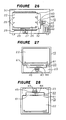
- Figures 27 and 28 show another embodiment of the microwave heating apparatus of the present invention.
- the size of opening of the power feeding ports 61 are the same that of the power feeding port 32, and the antenna of the magnetron 43 is arranged at a position having the same distance from the both power feeding ports 61.
- a substantially same amount of radiowaves can be supplied from the power feeding ports 61, so that further uniform cooking can be performed.
- an operation panel 23 is arranged at a lower portion of the front surface of the heating chamber 22, a waveguide 33 is provided at the outer bottom surface of the heating chamber 22, and a magnetron 43 is arranged below the waveguide 33. Accordingly, the bottom surface of the heating chamber 22 can be strengthened by the reinforcement of the waveguide 33 having a substantially rectangular prism body. This unnecessitates an additional special reinforcing material so that the heating chamber withstands a heavy cooking material.
- Figure 28 shows a modified embodiment of that shown in Figure 27.
- an operation panel 23 is arranged at a upper portion of the front surface of the heating chamber 22.
- a waveguide 33 is provided on the outer top surface of the heating chamber 22, and a magnetron 43 is mounted on the waveguide 33, whereby the top plate of the heating chamber 22 is reinforced by the waveguide 43 having a substantially rectangular prism body. Accordingly, a deflection of the heating chamber 22 can be prevented.
- the antenna 44 may be positioned to face one of the power feeding ports as shown in Figure 29.
- the position and the surface area of opening of the power feeding ports, the position of the antenna 44 and so on can be suitably determined. In this case, it is possible to obtain heat satisfactory even when a power feeding port is closed by a dish or a cup or the like.
- the surface area of opening of at least one power feeding port may be varied. Then, a state of power feeding can be changed depending on a material to be cooked, and uneven heating can be reduced.
- the same effect can be obtained by providing power feeding ports 62 at the upper and side surfaces of an L-like waveguide 33, and by arranging the antenna 44 in the waveguide so as to face the segment between the power feeding ports 62.
- An inverter may be used as a microwave oscillating apparatus for the magnetron.
- the microwave heating apparatus has the waveguide projecting uniformly on and along a wall or walls of the heating chamber, a plurality of power feeding ports for communicating the waveguide with the heating chamber, and the radiowave oscillating antenna arranged along the surface of the waveguide facing the segment between the power feeding ports. Accordingly, a cooking material can be heated uniformly. Further, the shape of the waveguide can be simple and the manufacturing cost can be reduced.
- the microwave heating apparatus has the waveguide having a substantially rectangular prism body connected to a wall of the heating chamber, power feeding ports formed at both end portions in the longitudinal direction of the waveguide and the microwave oscillating antenna arranged along the waveguide facing the portion between the power feeding ports. Therefore, a material to be heated can be uniformly heated. Further, the shape of the waveguide having the above-mentioned structure can be simple and the manufacturing cost can be greatly reduced. An additional power feeding port may be formed between the two power feeding ports so that microwaves are oscillated in the heating chamber through the three power feeding ports so that a cooking material can be further uniformly heated.
Abstract
Description
- The present invention relates to a microwave heating apparatus such as an electronic oven. More particularly, it relates to an improvement in the shape of a waveguide having a plurality of power feeding ports.
- There have been proposed microwave heating apparatuses with a waveguide in which a single power feeding port is formed. Figures 31 and 32 are respectively longitudinal cross-sectional views in schematic forms of an electronic oven which utilizes a conventional microwave heating apparatus. Description will be made with reference to Figures 31 and 32. A
reference numeral 1 designates a heating chamber, anumeral 2 designates a turn table positioned at the lower portion of theheating chamber 1 and adapted to receive thereon a material to be heated 6, anumeral 3 designates a magnetron for generating microwaves, anumeral 7 designates an antenna for emitting the microwaves, and anumeral 4 designates a waveguide which is attached to the outer wall of the ceiling of theheating chamber 1 and guides the microwaves emitted from themagnetron 3 to a power feeding port formed in the ceiling of theheating chamber 1. - The conventional electronic oven as shown in Figure 31 is so adapted that the material to be heated 6 (hereinbelow, referred to as a heating material) is placed on the turn table 2, and when a door is closed to actuate a power switch (not shown), the turn table 2 is started to rotate, and at the same time, microwaves are emitted from the
antenna 7 of themagnetron 3. The microwaves are supplied to theheating chamber 1 via thewaveguide 4 and thepower feeding port 5 to thereby heat theheating material 6. - Figure 32 shows another conventional technique, wherein a
power feeding port 5 is formed at the upper portion of a side wall of theheating chamber 1. Microwaves are supplied into theheating chamber 1 through thepower feeding port 5. Awaveguide 4 attached to the outer surface of the side wall of theheating chamber 1. The function of the apparatus as shown in Figure 32 is the same as that in Figure 31. - In the conventional microwave heating apparatuses, since only one
power feeding port 5 for supplying the microwaves into theheating chamber 1 is formed in the ceiling or a side wall, the microwaves can not be supplied uniformly to theheating material 6 as shown in Figures 31 and 32 to thereby often cause uneven heating to the heating material. Further, it takes much time to heat theheating material 6 depending on the position of the heating material, and much power is consumed. - To eliminate the above-mentioned problems, microwave heating apparatuses having a plurality of power feeding ports formed in a waveguide are proposed as shown in Figures 33 and 34. Figure 33 is a longitudinal cross-sectional view of a conventional microwave heating apparatus having power feeding ports formed in the ceiling of the heating chamber, which is described in, for instance, Japanese Examined Utility Model Publication 15589/1986. Figure 34 is a longitudinal cross-sectional view of a conventional microwave heating apparatus having power feeding ports in a side surface of the heating chamber. In Figure 33, a
numeral 1 designates a heating chamber, anumeral 8 designates a waveguide attached to the top surface of theheating chamber 1 so that an end of the waveguide projects from the right side portion of the top surface, anumeral 9 designates three power feeding ports formed in the top surface of theheating chamber 1 so as to communicate thewaveguide 8 with theheating chamber 1, anumeral 3 designates a magnetron as a microwave oscillating apparatus which is connected to the lower end of the projecting portion of thewaveguide 8 and has anantenna 7 extending in thewaveguide 8. In Figure 34, awaveguide 10 is provided at a side surface of theheating chamber 1, and two power feeding ports are formed at the side surface of theheating chamber 1 so as to communicate thewaveguide 10 with theheating chamber 1. - Let's assume that a wavelength of radiowaves oscillated from the
antenna 7 is λg. The distance from the center of theantenna 7 to the surface of thewaveguide 8 facing oppositely the surface where the power feeding ports are formed is called a back plunger which has a wavelength of λg/4, and it is usually determined to be 18.6 mm - 22 mm. - With respect to the backup plunger, it is introduced in, for instance, a publication "A lecture of practical microwave, a microwave circuit", p.148-149 by Mrs. Kunihiro Suetake and Shuichi Hayashi published by Ohm Sha on October 31, 1958, as follows. "Normally, a short circuit plate S is provided at a position apart from a length of about 1/4 from an antenna to cause a short circuit as shown in Figures (Figures 35 and 36). Thus, there is obtainable radiowaves propagating in the opposite direction".
- The microwave heating apparatus having more than two power feeding ports with the back plunger is disclosed in addition to the above-mentioned conventional apparatus, in publications such as Japanese Examined Patent Publication 37504/1987, Japanese Examined Patent Publication 30077/1985, Japanese Examined Utility Model Publication 22080/1987, Japanese Examined Utility Model Publication 31999/1987, Japanese Examined Utility Model Publication 30798/1987, Japanese Examined Utility Model Publication 11916/1986, Japanese Examined Utility Model Publication 35988/1985, Japanese Examined Utility Model Publication 35991/1985 and so on.
- In operations, microwaves oscillated from the
antenna 7 of themagnetron 3 are propagated toward theheating chamber 1 by the back plunger provided in thewaveguide heating chamber 1 through thepower feeding ports 6, whereby a material to be cooked placed in theheating chamber 1 is heated. - In the conventional microwave heating apparatus having the above-mentioned construction, the shape of the
waveguide power feeding ports power feeding ports 9 are formed at the central portion of the top surface of theheating chamber 1 and both end portions with respect to the central portion in order to reduce uneven heating as shown in Figure 33, the back plunger is assured by projecting an end of thewaveguide 8 from an end of the heating chamber, by connecting themagnetron 3 at the lower portion of the projecting part, and by inserting theantenna 7. - In a case that the power feeding ports are formed at the upper and lower portions of a side surface of the
heating chamber 1 as shown in Figure 34, the back plunger is assured by projecting the central portion of thewaveguide 10 in the lateral direction, by connecting themagnetron 3 to the lower portion of the projecting part, and by inserting theantenna 7. In either case of thewaveguides magnetron 3 and its connecting portion were unevenly projected with respect to theheating chamber 1. Accordingly, there arose problems that the structure of thewaveguide - Definitions of the uneven projection and the even projection will be described. In a case of a
waveguide 8 projecting from the top surface of a microwave heating apparatus main body as shown in Figure 37, a projecting portion is called an uneven projection. On the other hand, in a case of awaveguide 8 whose projectingportion 13 extend on and along another surface as shown in Figure 38, a projecting portion is calleduneven projection 13. There is proposed another technique as shown in Figure 39 that awaveguide 8 is attached to the top surface of the heating chamber so as to extend from an end to the other end, but so as not to project from theheating chamber 1,power feeding ports 14 are formed at the central portion and an end portion so as to communicate thewaveguide 8 with theheating chamber 1, and anantenna 7 for amagnetron 3 is arranged at a position apart from the end of thewaveguide 8 by a wavelength of λg/4. In this technique, however, the length of thewaveguide 8 is inevitably large and it is impossible to form the power feeding ports at both end portions. Further, it is difficult to reduce uneven heating because the plural power feeding ports are formed. - It is an object of the present invention to eliminate the above-mentioned problems and to provide a microwave heating apparatus having a waveguide of a simple structure and capable of reducing uneven heating to a material to be cooked.
- In accordance with the present invention, there is provided a microwave heating apparatus which comprises a microwave heating apparatus main body, a heating chamber provided in the microwave heating apparatus main body, a waveguide member for providing a waveguide projecting substantially uniformly along a wall of the heating chamber, a plurality of power feeding parts for communicating the inside of the waveguide with the heating chamber, and a microwave oscillating antenna arranged along the surface of the waveguide facing the segment between the power feeding parts.
- In accordance with the present invention, there is provided a microwave heating apparatus which comprises a microwave heating apparatus main body, a heating chamber provided in the microwave heating apparatus main body, a waveguide member connected to a wall of the heating chamber and forming a waveguide having a substantially rectangular body, power feeding parts formed at both end portions in the longitudinal direction of the waveguide, and a microwave oscillating antenna arranged along the surface of the waveguide facing the portion between the power feeding parts.
- In drawings:
- Figure 1 is a perspective view of an embodiment of the microwave heating apparatus of the present invention;
- Figure 2 is a perspective view partly broken of the microwave heating apparatus of the first embodiment;
- Figure 3 is a perspective view showing the back of the microwave heating apparatus as shown in Figure 1;
- Figure 4 is a schematic view showing the front part of the microwave heating apparatus as shown in Figure 1;
- Figure 5 is a perspective view of a waveguide in a disassembled state, which is used for the microwave heating apparatus as shown in Figure 1;
- Figure 6 is an elevation view partly omitted of a heating chamber in the microwave heating apparatus as shown in Figure 1;
- Figure 7 is a rear view of the waveguide used for the microwave heating apparatus as shown in Figure 1;
- Figure 8 is a longitudinal cross-sectional view of the waveguide as shown in Figure 7;
- Figure 9 is a front view of the waveguide as shown in Figure 7;
- Figure 10 is a structural diagram showing a side portion of the microwave heating apparatus of the first embodiment;
- Figures 11 and 12 diagrams showing comparative data of uneven heating obtained by using microwave heating apparatuses prepared in accordance with the present invention;
- Figures 13 and 14 are respectively a plane view and a longitudinal cross-sectional view schematically shown of a second embodiment of the microwave heating apparatus according to the present invention;
- Figures 15 and 16 are respectively a plane view and a longitudinal cross-sectional view schematically shown of a third embodiment of the microwave heating apparatus according to the present invention;
- Figures 17 and 18 are respectively a plane view and a longitudinal cross-sectional view schematically shown of a fourth embodiment of the microwave heating apparatus according to the present invention;
- Figures 19 and 20 are respectively a plane view and a longitudinal cross-sectional view schematically shown of a fifth embodiment of the microwave heating apparatus according to the present invention;
- Figures 21, 22 and 25 are respectively perspective views showing other embodiments of the microwave heating apparatus according to the present invention;
- Figures 23, 24 and 26 through 30 are respectively front views schematically shown of other embodiments of the microwave heating apparatus of the present invention;
- Figures 31 and 32 are respectively longitudinal cross-sectional views showing as forms of model conventional microwave heating apparatuses;
- Figures 33 and 34 are respectively front views showing conventional microwave heating apparatuses;
- Figures 35 and 36 are respectively a perspective view and a plane view partly broken of a back plunger;
- Figure 37 and 38 are respectively diagrams showing the structure of conventional waveguides; and
- Figure 39 is a diagram of a conventional microwave heating apparatus.
- Preferred embodiments of the microwave heating apparatus of the present invention will be described with reference to the drawings.
- Figures 1 through 10 show a first embodiment of the microwave heating apparatus of the present invention. In Figures 1 through 10, a
reference numeral 15 designates a microwave heating apparatus main body as a main part of an electronic oven, a numeral 16 designates a U-shaped casing havingair discharge ports 17 at a side surface, a numeral 18 designates a rear plate in whichair intake ports 19 are formed at the right side when viewed from the front of the electronic oven andair discharge ports 20 at the central portion, a numeral 21 designates a vertically opening type door pivotally supported at the lower edge portion of the front part of theelectronic oven 15, a numeral 22 designates a heating chamber formed in theelectronic oven 15 to have a capacity defined by a width of 343 mm, a depth of 340 mm and a height of 208 mm so that it communicate with the atmosphere by opening the vertically openingdoor 21, a numeral 23 designates an operating panel provided at the right side of the vertically openingdoor 21, and a numeral 24 designates dish receiving racks which are attached or formed on both side walls of theheating chamber 1 so as to project therefrom, wherein three rows of the racks are vertically arranged with equal distances at each of the side walls. The front part and the rear part of each of the dish receiving racks are formed in a generally rounded-like shape in vertical cross section. The intermediate portion of each of the dish receiving racks at the upper and middle stages is so formed that the edge portion of the -like portion is vertically cut, and the intermediate portion of the dish receiving racks at the lower stage has no cut portion. The shape of the intermediate portion of the
dish receiving racks 24 at the upper and middle stages is called arecess 25. - A numeral 26 designates a turn table to receive thereon a material to be cooked (hereinafter, referred to as a cooking material). The turn table is put on a
rotating plate 28 which is placed in theheating chamber 22 and has the lower surface connected to the shaft of a drivingmotor 27 which is provided at the central portion of the bottom of the microwave heating apparatus main body, i.e. below theheating chamber 22. A numeral 29 designates a lower heater consisting of a mica heater attached to the substantially entire region of the outer bottom surface of theheating chamber 22, and a numeral 30 designates an upper heater consisting of a mica heater placed on the substantially entire surface of the outer top surface of theheating chamber 22. A numeral 31 designates an upper feeding port having a dimension of 15 mm long and 82 mm wide which is formed in the right side wall of theheating chamber 22 and at a position having its center which is 16 mm lower than the upper edge of theheating chamber 22 and 195 mm deeper than the front edge of theheating chamber 22. A numeral 32 designates a lower feeding port having a dimension of 35 mm long and 82 mm wide which is formed in the same right side wall and at a portion having its center which is 173.5 mm lower than the upper edge and 195 mm deeper than the front edge of theheating chamber 22. A numeral 33 designates a waveguide as a waveguide member attached to an outer wall of theheating chamber 22 by spot welding so as to communicate the upper andlower feeding ports heating chamber 22. The outer configuration of the waveguide is in a substantially rectangular prism. - The
waveguide 33 is basically constituted by three structural elements as shown in Figure 5. This will be described in detail. A numeral 34 designates a guide plate having a dimension of 130 mm long, 110 mm wide and 0.6 mm thick which covers an uneven surface formed in the outer side wall of the heating chamber, the uneven surface being resulted from forming thedish receiving racks 24 in theheating chamber 22 at the position between the upper and lowerpower feeding ports guide plate 34 to thereby form anupper opening 36 and alower opening 37 which respectively face the upper and lowerpower feeding ports guide box 35 has aflange 38 of about 10 mm projecting from the outer circumference of the open surface. Both sides of the flange portion are connected to the outer side wall of theheating chamber 22 together with theguide plate 34 in an overlapping state, and the other portion of theflange 38 is directly connected to the outer wall of theheating chamber 22 by spot-welding. Thus, the upper and lowerpower feeding ports guide box 35 through the upper andlower openings guide box 15. - A numeral 39 designates a round opening having a diameter of 22 mm whose center is located at a point which is 55 mm lower than the upper surface of the
guide box 35 and at the center in the traversing direction of the surface of theguide box 35 which opposes the upper andlower openings round opening 39 is apart from the center of theupper opening 36 by 46.5 mm and is apart from the center of thelower opening 37 by 137.5 mm. - As clearly shown in Figures 7-9,
openings 40 for receiving terminals are formed in the opposing surface of theguide box 35 in order to connect the upper and lower end portions of theguide plate 34 to the outer side wall of theheating chamber 22 by spot-welding. Fouropenings 40 are arranged in line with intervals of 22 mm at positions 35.5 mm higher than the center of theround opening 39, and four openings are arranged in line with intervals of 22 mm at positions 85.5 mm lower than theround opening 39. A numeral 41 designates a magnetron supporting plate having a dimension of 100 mm long and 122 mm wide which is spot-welded around theround opening 39 of theguide box 35, and has anopening 42 having a diameter of 31 mm which opens facing theround opening 39. The entire circumference of themagnetron supporting plate 41 is bent at a right angle in the direction opposite theguide box 34. The right and left side portions of themagnetron supporting plate 41 are separated from the outer surface of theguide box 35. Thus, thewaveguide 33 comprises theguide plate 34, theguide box 35 and themagnetron supporting plate 41. - Description will be made as to peripheral devices for the
waveguide 33 with reference to Figure 10. A numeral 43 designates a magnetron as a microwave oscillating device which is secured to an element attached to theguide box 35 through themagnetron supporting plate 41 by means of three screws.and two pawls. Further, anantenna 44 is inserted in theopenings magnetron 43. A numeral 46 designates a duct having an end which is opened to the left side surfaces of the coolingfins 45 and the other end which is opened to a plurality ofapertures 47 perforated at the upper part of the outer side wall of theheating chamber 22 to face the vertically openingdoor 21. A numeral 48 designates a high frequency transformer placed just below themagnetron 43. A numeral 49 designate a blower positioned above and behind themagnetron 43. The blower is so supported that the blades of the blower face an opening of afan fitting plate 50 which is so constructed that round opening is formed in a upright rectangular flat plate. A packing 51 for anti-leakage is bonded to the circumferential surface of thefan fitting plate 50 so as to be in contact with the inner wall of thecasing 16 for theelectronic oven 15. A numeral 52 designates a high voltage relay located just below theblower 49, a numeral 53 designates a high voltage capacitor located behind thehigh voltage relay 52, a numeral 54 designates electronic elements comprising a plurality of substrates which are provided behind the operating panel, and a numeral 55 designates a thermostat attached to themagnetron 43. - As described above, since the
antenna 44 is positioned between the upper and lowerpower feeding ports power feeding ports - For a power feeding method A, a microwave heating apparatus having the same construction as described above was used. In a microwave heating apparatus used for a power feeding method B, the size of opening of the upper
power feeding port 31 is same as that of the lowerpower feeding port 32. In a power feeding method C, a microwave heating apparatus having a single power feeding port which is the same as the conventional apparatus was used. - As is clear from the diagrams, uneven heating in the case of the power feeding methods A, B is less than that of the power feeding method C, and oscillation of microwaves was excellent. Thus, the construction of the
waveguide 33 in which the waveguide does not project from an end of theheating chamber 22 in an uneven state reduces cost for materials and processes, improves easiness of assembling and services, and reduces the size of the microwave heating apparatus. - Since the
waveguide 33 of a substantially rectangular prism is connected to a wall surface of the heating chamber, the wall surface attached with thewaveguide 33 can be reinforced due to the fact that thewaveguide 33 uniformly faces the wall surface, hence it can uniformly receive an external force, in comparison with the conventional microwave heating apparatus in which an end of the waveguide projects from the wall surface of the microwave heating main body. In particular, a trouble such as dropping of a dish which is caused by the spreading of the distance between a pair of dish receiving racks by the expansion of theheating chamber 22 when an electric oven is used, can be prevented. - An air layer in the
waveguide 33 functions as an insulating material against the wall surface to which thewaveguide 33 is connected. - In the above-mentioned first embodiment, the microwave heating apparatus is so constructed that the lower
power feeding port 32 has a larger opening than the upperpower feeding port 31, and the antenna for oscillating microwaves faces to the upperpower feeding port 31. However, the position and the shape of thewaveguide 33, the positions of the power feeding ports, the surface area and the shape of the opening for the ports, the position of the antenna and so on may be determined as desired depending on the shape and the volume of theheating chamber 22. Thus, the optimum heating can be given to a heating material by changing a quantity of power fed through each of the power feeding ports. - Figures 13 and 14 are respectively plane view and a longitudinal cross-sectional view schematically shown of a second embodiment of the microwave heating apparatus. In Figures 13 and 14, the same reference numerals as in Figures 1 through 10 designate the same or corresponding parts, and therefore, description of these parts is omitted. An upper
power feeding port 31 is formed at the upper part of a side wall of theheating chamber 22 and a lowerpower feeding port 32 is formed at a lower part of it. Awaveguide 33 with amagnetron 43 is attached to the outer surface of a side wall of theheating chamber 22 so as to be communicated with the upper and lowerpower feeding ports - In the second embodiment, the lower
power feeding port 32 is provided at a place lower than a material to be heated 6. The dimension in the vertical direction (in the direction of height) of the upper powerfeeding feeding port 31 is 15 mm and the dimension of the lowerpower feeding port 32 is 35 mm, which is greater than the upperpower feeding port 31. - In the second embodiment having the construction as described above, microwaves are fed in the
heating chamber 22 through the upper and lowerpower feeding ports power feeding port 31 is provided at a lower part of thematerial 6, the microwaves are supplied to the upper and lower portion of thematerial 6, whereby a time of heating can be further shortened. - Figures 15 and 16 are respectively diagrams showing a third embodiment of the microwave heating apparatus according to the present invention. In the third embodiment, the upper and lower
power feeding ports heating chamber 22, and awaveguide 33 with amagnetron 43 is fixed to the corner portion of the outer side of the side wall of theheating chamber 22. - In the third embodiment, a small bottle or a cup containing a water-
rich material 6 such as "sake" (Japanese wine), milk or the like can be directly placed at the corner portion of the bottom plate of the heating chamber which does not interfere with the rotation of the turn table 26. Then, thematerial 6 to be heated can be heated from the upper and side directions to thereby reduce the possibility of uneven heating, and shorten a time of heating. In this case, it is possible to stop the rotation of the turn table 26 if necessary. - Figures 17 and 18 show a fourth embodiment of the microwave heating apparatus of the present invention. In the fourth embodiment, an
upper feeding port 31 is formed at the upper portion of a side wall of the heating chamber, and a lowerpower feeding port 32 is formed in the side wall and near the turn table 26. Awaveguide 33 is attached to the outer surface of the side wall of theheating chamber 22. - In the above-mentioned construction, a water-
rich material 6 to be heated can be placed on the turn table 26 so as to be close to the lowerpower feeding port 32. When the turn table 26 is stopped and thematerial 6 is heated, microwaves are supplied from the upper and side directions to thematerial 6, whereby a possibility of uneven heating can be reduced and the material can be heated for a short time. - Figures 19 and 20 show a fifth embodiment of the present invention. In the fifth embodiment, an upper
power feeding port 31 is formed at an upper corner portion in a side wall of theheating chamber 22, and alower feeding port 32 is formed in the bottom surface of theheating chamber 22. Further, awaveguide 33 is attached to the heating chamber so as to cover the upper and lowerpower feeding ports material 6 is directly put on the lowerpower feeding port 32. Accordingly, heat is given to thematerial 6 with a small temperature difference between the upper and lower portions, and the material can be heated for a short time. - In the above-mentioned embodiments, the upper power feeding port is formed at the upper portion of a side wall of the heating chamber, and a lower power feeding port is formed at the bottom surface or a lower portion of the side wall of the heating chamber. However, the upper power feeding port may be formed in the ceiling of the heating chamber.
- In the first through fifth embodiments, the
guide box 35 of thewaveguide 33 is attached to theheating chamber 22 so that the upper and lower surfaces of theguide box 35 are respectively perpendicular to the side wall of theheating chamber 22. However, the upper and lower surfaces of theguide box 35 may be inclined so that a skirt portion is formed at the surface for mounting themagnetron 43 of theguide box 35 to the surface which is in contact with the outer surface of theheating chamber 22 as shown in Figure 21. Thus, by forming tapered portions at the upper and lower surfaces of theguide box 35, thewaveguide 33 can be formed by drawing operations. Accordingly, the manufacturing cost can be reduced because only stamping operations are needed for manufacturing the waveguide. The same effect can be obtained by forming the upper and lower surfaces in a spherical form. Further, a tapered portion may be formed at a side surface of thewaveguide 33. Accordingly, in the above-mentioned description, thewaveguide 33 having a substantially rectangular prism includes embodiments having the above-mentioned tapered surface or spherical surface. - In the first-fifth embodiments, the
waveguide 33 is provided at the outer wall of theheating chamber 22. However, it may be formed in or be attached to the inside of theheating chamber 22 as shown in Figures 22 through 25. With such construction, it seems that themagnetron 43 is directly attached to theheating chamber 22 in appearance. Accordingly, other structural elements can be arranged at suitable positions, and it is possible to reduce the size of the microwave heating apparatusmain body 15. - In the
waveguide 33 as shown in Figure 24,step portions 56 are formed at both sides of the upper surface of theheating chamber 22, and aflat plate 58 in which twopower feeding ports 57 are formed is mounted on theheating chamber 25 so as to bridge thestep portions 56. In thewaveguide 33 thus formed, the manufacturing cost can be greatly reduced. - In the
waveguide 33 as shown in Figure 25, the central portion in the shorter side of a rectangular flat plate is stamped to form a recess, and both side portions in the shorter side of the rectangular flat plate are connected to the top surface of theheating chamber 22 by spot-welding, so thatpower feeding ports 59 are formed at both ends in the longitudinal direction of the heating chamber. Thus formedwaveguide 33 reduces the manufacturing cost. - Figure 26 shows another embodiment of the microwave heating apparatus of the present invention. In this embodiment, an intermediate
power feeding port 60 is formed between upper and lowerpower feeding ports - Figures 27 and 28 show another embodiment of the microwave heating apparatus of the present invention. In Figures 27 and 28, the size of opening of the
power feeding ports 61 are the same that of thepower feeding port 32, and the antenna of themagnetron 43 is arranged at a position having the same distance from the bothpower feeding ports 61. In the embodiment as shown in Figures 27 and 28, a substantially same amount of radiowaves can be supplied from thepower feeding ports 61, so that further uniform cooking can be performed. - In the embodiment as shown in Figure 27, an
operation panel 23 is arranged at a lower portion of the front surface of theheating chamber 22, awaveguide 33 is provided at the outer bottom surface of theheating chamber 22, and amagnetron 43 is arranged below thewaveguide 33. Accordingly, the bottom surface of theheating chamber 22 can be strengthened by the reinforcement of thewaveguide 33 having a substantially rectangular prism body. This unnecessitates an additional special reinforcing material so that the heating chamber withstands a heavy cooking material. - Figure 28 shows a modified embodiment of that shown in Figure 27. In this embodiment, an
operation panel 23 is arranged at a upper portion of the front surface of theheating chamber 22. In this case, awaveguide 33 is provided on the outer top surface of theheating chamber 22, and amagnetron 43 is mounted on thewaveguide 33, whereby the top plate of theheating chamber 22 is reinforced by thewaveguide 43 having a substantially rectangular prism body. Accordingly, a deflection of theheating chamber 22 can be prevented. - Alternatively, the
antenna 44 may be positioned to face one of the power feeding ports as shown in Figure 29. - In order to obtain a sufficient power feeding in a case that any of the power feeding ports is unexpectedly closed, the position and the surface area of opening of the power feeding ports, the position of the
antenna 44 and so on can be suitably determined. In this case, it is possible to obtain heat satisfactory even when a power feeding port is closed by a dish or a cup or the like. - Further, the surface area of opening of at least one power feeding port may be varied. Then, a state of power feeding can be changed depending on a material to be cooked, and uneven heating can be reduced.
- The same effect can be obtained by providing
power feeding ports 62 at the upper and side surfaces of an L-like waveguide 33, and by arranging theantenna 44 in the waveguide so as to face the segment between thepower feeding ports 62. - An inverter may be used as a microwave oscillating apparatus for the magnetron.
- Thus, in accordance with the first invention, the microwave heating apparatus has the waveguide projecting uniformly on and along a wall or walls of the heating chamber, a plurality of power feeding ports for communicating the waveguide with the heating chamber, and the radiowave oscillating antenna arranged along the surface of the waveguide facing the segment between the power feeding ports. Accordingly, a cooking material can be heated uniformly. Further, the shape of the waveguide can be simple and the manufacturing cost can be reduced.
- In accordance with the second invention, the microwave heating apparatus has the waveguide having a substantially rectangular prism body connected to a wall of the heating chamber, power feeding ports formed at both end portions in the longitudinal direction of the waveguide and the microwave oscillating antenna arranged along the waveguide facing the portion between the power feeding ports. Therefore, a material to be heated can be uniformly heated. Further, the shape of the waveguide having the above-mentioned structure can be simple and the manufacturing cost can be greatly reduced. An additional power feeding port may be formed between the two power feeding ports so that microwaves are oscillated in the heating chamber through the three power feeding ports so that a cooking material can be further uniformly heated.
Claims (6)
a microwave heating apparatus main body (15),
a heating chamber (22) provided in the microwave heating apparatus main body,
a waveguide member (33) for providing a waveguide projecting substantially uniformly along a wall of the heating chamber (22), characterized by a plurality of power feeding ports (31, 32, 36, 37; 57; 62) for communicating the inside of the waveguide with the heating chamber, and
a microwave oscillating antenna (44) arranged along the surface of the waveguide (33) facing the segment or portion between the power feeding ports (3).
the power feeding ports (31, 32, 36, 37) are formed at both end portions in the longitudinal direction of the waveguide (3).
Applications Claiming Priority (4)
| Application Number | Priority Date | Filing Date | Title |
|---|---|---|---|
| JP31367588A JPH02160395A (en) | 1988-12-14 | 1988-12-14 | High frequency heating device |
| JP313675/88 | 1988-12-14 | ||
| JP123174/89 | 1989-05-17 | ||
| JP1123174A JP2524402B2 (en) | 1989-05-17 | 1989-05-17 | High frequency heating equipment |
Publications (3)
| Publication Number | Publication Date |
|---|---|
| EP0373608A2 true EP0373608A2 (en) | 1990-06-20 |
| EP0373608A3 EP0373608A3 (en) | 1992-01-15 |
| EP0373608B1 EP0373608B1 (en) | 1995-02-08 |
Family
ID=26460171
Family Applications (1)
| Application Number | Title | Priority Date | Filing Date |
|---|---|---|---|
| EP89122965A Expired - Lifetime EP0373608B1 (en) | 1988-12-14 | 1989-12-12 | Microwave heating apparatus |
Country Status (5)
| Country | Link |
|---|---|
| US (2) | US5015813A (en) |
| EP (1) | EP0373608B1 (en) |
| AU (1) | AU625617B2 (en) |
| DE (1) | DE68921050T2 (en) |
| NZ (1) | NZ231737A (en) |
Cited By (9)
| Publication number | Priority date | Publication date | Assignee | Title |
|---|---|---|---|---|
| EP0453928A2 (en) * | 1990-04-25 | 1991-10-30 | Kabushiki Kaisha Toshiba | High frequency heating apparatus |
| FR2686684A1 (en) * | 1992-01-23 | 1993-07-30 | Toshiba Ave Kk | High-frequency heating apparatus |
| ES2091157A2 (en) * | 1994-02-25 | 1996-10-16 | Gold Star Co | Wave-guide system for a microwave oven. |
| FR2751055A1 (en) * | 1996-07-15 | 1998-01-16 | Moulinex Sa | ELECTRIC COOKING OVEN |
| WO2000007412A1 (en) * | 1998-07-31 | 2000-02-10 | Jury Yakovlevich Brodsky | Microwave oven |
| WO2002035886A2 (en) * | 2000-10-25 | 2002-05-02 | Whirlpool Corporation | Feeding of microwaves |
| WO2004071133A1 (en) | 2003-02-05 | 2004-08-19 | Matsushita Electric Industrial Co., Ltd. | Microwave heating device |
| EP1670290A1 (en) * | 2004-12-13 | 2006-06-14 | Topinox Sarl | Cooking appartus with microwave generation unit |
| WO2013148238A1 (en) * | 2012-03-26 | 2013-10-03 | Mag Aerospace Industries, Inc. | Combination microwave/warmer and oven |
Families Citing this family (13)
| Publication number | Priority date | Publication date | Assignee | Title |
|---|---|---|---|---|
| SE9003012L (en) * | 1990-09-21 | 1991-09-16 | Whirlpool Int | MICROWAVE OVEN, METHOD FOR EXCITING THE CAVITY IN A MICROWAVE OVEN, AND GUIDANCE MANUAL FOR THE IMPLEMENTATION OF THE METHOD |
| SE467336B (en) * | 1990-09-28 | 1992-06-29 | Whirlpool Int | MICROWAVE OVEN WITH BROWNERS, BROWN PLATE FOR USE IN A MICROWAVE OVEN |
| FR2673350B1 (en) * | 1991-02-22 | 2001-09-28 | Moulinex Sa | WAVEGUIDE FOR MICROWAVE OVEN. |
| KR950003782B1 (en) * | 1992-08-25 | 1995-04-18 | 주식회사금성사 | Microwave range with a two-way heating system |
| JP3019239B2 (en) * | 1992-10-28 | 2000-03-13 | 船井電機株式会社 | microwave |
| SE501441C2 (en) * | 1993-06-18 | 1995-02-13 | Whirlpool Europ | Process for heating to a finished temperature of liquid beverages or foodstuffs, microwave oven for carrying out the process, and use of a microwave oven for heating beverages in molded packages |
| SE501494C2 (en) * | 1993-07-02 | 1995-02-27 | Whirlpool Europ | Microwave Input Method of a Microwave Heater and Microwave Heater |
| US6043100A (en) * | 1996-04-19 | 2000-03-28 | Weaver; Kevin | Chip on tape die reframe process |
| KR100239552B1 (en) * | 1997-10-15 | 2000-03-02 | 윤종용 | Microwave oven |
| US7586068B2 (en) * | 2005-01-04 | 2009-09-08 | Peter Shaw | Disposable microwave food shield |
| US7414229B2 (en) * | 2005-01-04 | 2008-08-19 | Hellmann Michael G | Disposable microwave food shield |
| WO2011027571A1 (en) * | 2009-09-07 | 2011-03-10 | パナソニック株式会社 | Microwave heating device |
| JP5588989B2 (en) | 2009-09-16 | 2014-09-10 | パナソニック株式会社 | Microwave heating device |
Citations (8)
| Publication number | Priority date | Publication date | Assignee | Title |
|---|---|---|---|---|
| FR1378280A (en) * | 1963-10-04 | 1964-11-13 | Method and device for driving a microwave heating furnace | |
| US3373259A (en) * | 1965-03-26 | 1968-03-12 | Lyons & Co Ltd J | Electronic oven |
| FR2260918A1 (en) * | 1974-02-08 | 1975-09-05 | Matsushita Electric Ind Co Ltd | |
| FR2310058A1 (en) * | 1975-04-30 | 1976-11-26 | Matsushita Electric Ind Co Ltd | MICROWAVE HEATING DEVICE |
| US4329557A (en) * | 1979-12-07 | 1982-05-11 | General Electric Company | Microwave oven with improved energy distribution |
| US4336434A (en) * | 1980-08-15 | 1982-06-22 | General Electric Company | Microwave oven cavity excitation system employing circularly polarized beam steering for uniformity of energy distribution and improved impedance matching |
| EP0200100A2 (en) * | 1985-04-17 | 1986-11-05 | Matsushita Electric Industrial Co., Ltd. | Heat cooking apparatus |
| EP0227397A2 (en) * | 1985-12-17 | 1987-07-01 | Matsushita Electric Industrial Co., Ltd. | High frequency heating device |
Family Cites Families (20)
| Publication number | Priority date | Publication date | Assignee | Title |
|---|---|---|---|---|
| US2704802A (en) * | 1952-05-22 | 1955-03-22 | Raytheon Mfg Co | Microwave ovens |
| GB977777A (en) * | 1962-02-02 | 1964-12-16 | Lyons & Co Ltd J | Improvements in or relating to radio frequency ovens |
| CH426051A (en) * | 1965-10-25 | 1966-12-15 | Patelhold Patentverwertung | Microwave treatment tunnel |
| SE345903B (en) * | 1970-12-21 | 1972-06-12 | Philips Svenska Ab | |
| JPS5210937A (en) * | 1975-07-15 | 1977-01-27 | Matsushita Electric Ind Co Ltd | High frequency heating device |
| JPS5223744A (en) * | 1975-08-18 | 1977-02-22 | Matsushita Electric Ind Co Ltd | High frequency heating device |
| JPS532742A (en) * | 1976-06-29 | 1978-01-11 | Matsushita Electric Ind Co Ltd | High frequency heating device |
| US4159406A (en) * | 1977-05-31 | 1979-06-26 | Whirlpool Corporation | Waveguide assembly for microwave oven |
| JPS5824431A (en) * | 1981-08-06 | 1983-02-14 | Sumitomo Rubber Ind Ltd | Method for preheating elastomer article |
| JPS6030077A (en) * | 1983-07-29 | 1985-02-15 | 高周波熱錬株式会社 | Method of supplyig power to high frequency induction heating power source |
| JPS6035988A (en) * | 1983-08-04 | 1985-02-23 | Canon Inc | Controller of motor |
| JPS6035991A (en) * | 1983-08-05 | 1985-02-23 | Meidensha Electric Mfg Co Ltd | Automatic stabilization controller of sectional drive device |
| JPS6111916A (en) * | 1984-06-27 | 1986-01-20 | Nec Corp | Inspecting method of magnetic head |
| JPS6115589A (en) * | 1984-06-28 | 1986-01-23 | Daikin Ind Ltd | Vibration reducing unit of rotary compressor |
| JPH0631307B2 (en) * | 1985-04-27 | 1994-04-27 | 三共株式会社 | Process for producing griseo-acid derivative |
| FR2583250B1 (en) * | 1985-06-07 | 1989-06-30 | France Etat | METHOD AND DEVICE FOR EXCITTING A MICROWAVE PLASMA WITH ELECTRONIC CYCLOTRONIC RESONANCE |
| JPS6222080A (en) * | 1985-07-22 | 1987-01-30 | Nec Corp | Integrated circuit |
| JPS6237504A (en) * | 1985-08-12 | 1987-02-18 | Ebara Res Co Ltd | Cavitation producing device employing pump piping |
| JPH0632295B2 (en) * | 1988-04-04 | 1994-04-27 | 三洋電機株式会社 | microwave |
| DE3912569A1 (en) * | 1989-04-17 | 1990-10-18 | Siemens Ag | METHOD AND DEVICE FOR GENERATING AN ELECTRICAL HIGH FREQUENCY FIELD IN A UTILITY ROOM |
-
1989
- 1989-12-12 EP EP89122965A patent/EP0373608B1/en not_active Expired - Lifetime
- 1989-12-12 DE DE68921050T patent/DE68921050T2/en not_active Expired - Fee Related
- 1989-12-12 NZ NZ231737A patent/NZ231737A/en unknown
- 1989-12-13 US US07/450,250 patent/US5015813A/en not_active Expired - Lifetime
- 1989-12-13 AU AU46190/89A patent/AU625617B2/en not_active Expired
-
1990
- 1990-11-20 US US07/615,969 patent/US5057660A/en not_active Expired - Lifetime
Patent Citations (8)
| Publication number | Priority date | Publication date | Assignee | Title |
|---|---|---|---|---|
| FR1378280A (en) * | 1963-10-04 | 1964-11-13 | Method and device for driving a microwave heating furnace | |
| US3373259A (en) * | 1965-03-26 | 1968-03-12 | Lyons & Co Ltd J | Electronic oven |
| FR2260918A1 (en) * | 1974-02-08 | 1975-09-05 | Matsushita Electric Ind Co Ltd | |
| FR2310058A1 (en) * | 1975-04-30 | 1976-11-26 | Matsushita Electric Ind Co Ltd | MICROWAVE HEATING DEVICE |
| US4329557A (en) * | 1979-12-07 | 1982-05-11 | General Electric Company | Microwave oven with improved energy distribution |
| US4336434A (en) * | 1980-08-15 | 1982-06-22 | General Electric Company | Microwave oven cavity excitation system employing circularly polarized beam steering for uniformity of energy distribution and improved impedance matching |
| EP0200100A2 (en) * | 1985-04-17 | 1986-11-05 | Matsushita Electric Industrial Co., Ltd. | Heat cooking apparatus |
| EP0227397A2 (en) * | 1985-12-17 | 1987-07-01 | Matsushita Electric Industrial Co., Ltd. | High frequency heating device |
Cited By (17)
| Publication number | Priority date | Publication date | Assignee | Title |
|---|---|---|---|---|
| EP0453928A2 (en) * | 1990-04-25 | 1991-10-30 | Kabushiki Kaisha Toshiba | High frequency heating apparatus |
| EP0453928A3 (en) * | 1990-04-25 | 1992-12-23 | Kabushiki Kaisha Toshiba | High frequency heating apparatus |
| FR2686684A1 (en) * | 1992-01-23 | 1993-07-30 | Toshiba Ave Kk | High-frequency heating apparatus |
| US5451751A (en) * | 1992-01-23 | 1995-09-19 | Kabushiki Kaisha Toshiba | High-frequency heating apparatus with wave guide switching means and selective power switching means for magnetron |
| ES2091157A2 (en) * | 1994-02-25 | 1996-10-16 | Gold Star Co | Wave-guide system for a microwave oven. |
| US6057535A (en) * | 1996-07-15 | 2000-05-02 | Moulinex S.A. | Electric cooking oven with improved energy distribution |
| WO1998003041A1 (en) * | 1996-07-15 | 1998-01-22 | Moulinex S.A. | Electric cooking oven |
| FR2751055A1 (en) * | 1996-07-15 | 1998-01-16 | Moulinex Sa | ELECTRIC COOKING OVEN |
| WO2000007412A1 (en) * | 1998-07-31 | 2000-02-10 | Jury Yakovlevich Brodsky | Microwave oven |
| WO2002035886A2 (en) * | 2000-10-25 | 2002-05-02 | Whirlpool Corporation | Feeding of microwaves |
| WO2002035886A3 (en) * | 2000-10-25 | 2002-06-27 | Whirlpool Co | Feeding of microwaves |
| WO2004071133A1 (en) | 2003-02-05 | 2004-08-19 | Matsushita Electric Industrial Co., Ltd. | Microwave heating device |
| EP1592286A1 (en) * | 2003-02-05 | 2005-11-02 | Matsushita Electric Industrial Co., Ltd. | Microwave heating device |
| EP1592286A4 (en) * | 2003-02-05 | 2007-06-06 | Matsushita Electric Ind Co Ltd | Microwave heating device |
| US7928350B2 (en) | 2003-02-05 | 2011-04-19 | Panasonic Corporation | Microwave heating device |
| EP1670290A1 (en) * | 2004-12-13 | 2006-06-14 | Topinox Sarl | Cooking appartus with microwave generation unit |
| WO2013148238A1 (en) * | 2012-03-26 | 2013-10-03 | Mag Aerospace Industries, Inc. | Combination microwave/warmer and oven |
Also Published As
| Publication number | Publication date |
|---|---|
| AU625617B2 (en) | 1992-07-16 |
| DE68921050D1 (en) | 1995-03-23 |
| DE68921050T2 (en) | 1995-09-21 |
| EP0373608B1 (en) | 1995-02-08 |
| AU4619089A (en) | 1990-06-21 |
| NZ231737A (en) | 1991-11-26 |
| US5057660A (en) | 1991-10-15 |
| US5015813A (en) | 1991-05-14 |
| EP0373608A3 (en) | 1992-01-15 |
Similar Documents
| Publication | Publication Date | Title |
|---|---|---|
| US5015813A (en) | Power feeding port arrangement for a microwave heating apparatus | |
| US4743728A (en) | Dual path air circulation system for microwave ovens | |
| EP0429822B1 (en) | Combined microwave and forced convection oven | |
| EP0091779A2 (en) | Microwave heater | |
| JPH06111933A (en) | Waveguide system of microwave oven | |
| US4463239A (en) | Rotating slot antenna arrangement for microwave oven | |
| CA1163682A (en) | Microwave oven feed system | |
| CA1263452A (en) | Rotating slot antenna arrangement for microwave oven | |
| US4496814A (en) | Microwave excitation system | |
| JPH0658552A (en) | Microwave oven | |
| KR950013271B1 (en) | Triangular antena array for microwave oven | |
| CA1202374A (en) | High-frequency heating device | |
| US3975606A (en) | Microwave oven with uniform electric field distribution | |
| KR100320669B1 (en) | Heating cooker | |
| JP2558877B2 (en) | High frequency heating equipment | |
| US4412117A (en) | Microwave oven feed system | |
| JP2524402B2 (en) | High frequency heating equipment | |
| JPH03173094A (en) | High-frequency heating device | |
| KR890004873Y1 (en) | Equiverant heating apparatus for microwave range | |
| KR20050036439A (en) | A structure of lower plate of cavity for microwave oven | |
| KR960005566Y1 (en) | Packing box for accessory of microwave oven | |
| JPH0130275B2 (en) | ||
| JPH09320756A (en) | High-frequency heating apparatus | |
| KR100324507B1 (en) | Microwave oven | |
| JPH05190272A (en) | Microwave oven |
Legal Events
| Date | Code | Title | Description |
|---|---|---|---|
| PUAI | Public reference made under article 153(3) epc to a published international application that has entered the european phase |
Free format text: ORIGINAL CODE: 0009012 |
|
| AK | Designated contracting states |
Kind code of ref document: A2 Designated state(s): DE GB |
|
| 17P | Request for examination filed |
Effective date: 19901212 |
|
| PUAL | Search report despatched |
Free format text: ORIGINAL CODE: 0009013 |
|
| AK | Designated contracting states |
Kind code of ref document: A3 Designated state(s): DE GB |
|
| 17Q | First examination report despatched |
Effective date: 19930528 |
|
| GRAA | (expected) grant |
Free format text: ORIGINAL CODE: 0009210 |
|
| AK | Designated contracting states |
Kind code of ref document: B1 Designated state(s): DE GB |
|
| REF | Corresponds to: |
Ref document number: 68921050 Country of ref document: DE Date of ref document: 19950323 |
|
| PLBE | No opposition filed within time limit |
Free format text: ORIGINAL CODE: 0009261 |
|
| STAA | Information on the status of an ep patent application or granted ep patent |
Free format text: STATUS: NO OPPOSITION FILED WITHIN TIME LIMIT |
|
| 26N | No opposition filed | ||
| PGFP | Annual fee paid to national office [announced via postgrant information from national office to epo] |
Ref country code: DE Payment date: 19981221 Year of fee payment: 10 |
|
| REG | Reference to a national code |
Ref country code: GB Ref legal event code: 746 Effective date: 19990527 |
|
| PG25 | Lapsed in a contracting state [announced via postgrant information from national office to epo] |
Ref country code: DE Free format text: LAPSE BECAUSE OF NON-PAYMENT OF DUE FEES Effective date: 20001003 |
|
| REG | Reference to a national code |
Ref country code: GB Ref legal event code: IF02 |
|
| PGFP | Annual fee paid to national office [announced via postgrant information from national office to epo] |
Ref country code: GB Payment date: 20081210 Year of fee payment: 20 |
|
| REG | Reference to a national code |
Ref country code: GB Ref legal event code: PE20 Expiry date: 20091211 |
|
| PG25 | Lapsed in a contracting state [announced via postgrant information from national office to epo] |
Ref country code: GB Free format text: LAPSE BECAUSE OF EXPIRATION OF PROTECTION Effective date: 20091211 |