EP0227397A2 - High frequency heating device - Google Patents
High frequency heating device Download PDFInfo
- Publication number
- EP0227397A2 EP0227397A2 EP86309738A EP86309738A EP0227397A2 EP 0227397 A2 EP0227397 A2 EP 0227397A2 EP 86309738 A EP86309738 A EP 86309738A EP 86309738 A EP86309738 A EP 86309738A EP 0227397 A2 EP0227397 A2 EP 0227397A2
- Authority
- EP
- European Patent Office
- Prior art keywords
- wave guide
- high frequency
- heating chamber
- cylindrical wave
- wall
- Prior art date
- Legal status (The legal status is an assumption and is not a legal conclusion. Google has not performed a legal analysis and makes no representation as to the accuracy of the status listed.)
- Granted
Links
Images


Classifications
-
- H—ELECTRICITY
- H05—ELECTRIC TECHNIQUES NOT OTHERWISE PROVIDED FOR
- H05B—ELECTRIC HEATING; ELECTRIC LIGHT SOURCES NOT OTHERWISE PROVIDED FOR; CIRCUIT ARRANGEMENTS FOR ELECTRIC LIGHT SOURCES, IN GENERAL
- H05B6/00—Heating by electric, magnetic or electromagnetic fields
- H05B6/64—Heating using microwaves
- H05B6/6402—Aspects relating to the microwave cavity
-
- H—ELECTRICITY
- H05—ELECTRIC TECHNIQUES NOT OTHERWISE PROVIDED FOR
- H05B—ELECTRIC HEATING; ELECTRIC LIGHT SOURCES NOT OTHERWISE PROVIDED FOR; CIRCUIT ARRANGEMENTS FOR ELECTRIC LIGHT SOURCES, IN GENERAL
- H05B6/00—Heating by electric, magnetic or electromagnetic fields
- H05B6/64—Heating using microwaves
- H05B6/72—Radiators or antennas
Definitions
- the present invention relates to feed means of a high frequency or radio frequency (abbreviated as RF) heating device which heats an object such as food by high frequency dielectric heating, and more particularly to the prevention of leakage of higher harmonic electromagnetic wave compoents other than a fundamental frequency electromagnetic wave component used for the heating purpose.
- RF radio frequency
- a frequency band permitted for use in an R.F. heating device is limited to a specific band (usually called an ISM band), although it may differ from country to country to be 9l5 MHz band, 2450 MHz band, etc. So long as there is no danger to human body and safety is assured, there is no legal regulation on the frequency band.
- an RF oscillator usually generates higher harmonic components.
- a magnetron which is a microwave oscillator oscillating at a foundametal frequency (fo) of 2450 MHz
- relatively high power components are generated at 4900 MHz, 7350 MHz, 9800 MHz and l2250 MHz which are integral order higher harmonic components of the fundamental frequency (those components are represented by 2fo, 3fo, 4fo and 5fo).
- Figs. l and 2 show schematic sectional views of prior art RF heating devices having such a kind of means.
- a wave guide 3 is used as means for coupling a rectangular heating chamber l formed by conductive walls to an RF oscillator 2.
- An object 4 to be heated is placed in the heating chamber on a plate 5 made of a low dielectric material.
- the heating chamber walls have exhaust holes 6, through which water vapor generated from the object 4 during the heating is exhausted, and air inlet holes 7, through which fresh air is supplied, and a door 8 through which the object 4 is taken in and out of the heating chamber l.
- RF electromagnetic waves including higher harmonic components generated by the RF oscillator 2 is directed to the heating chamber l through the wave guide 3.
- the higher harmonic components are fed into the heating chamber l, they are transmitted out of the RF heating device through many paths such as the exhaust holes 6, air inlet holes 7 and clearances between the door 8 and the heating chamber walls. As a result, it is difficult to design electromagnetic wave leakage prevention means to be arranged around the door.
- conductive bars 9, l0 and ll of different lengths are mounted in the wave guide 3 to form a resonator operating as a band-pass filter in order to prevent the transmission of higher harmonic components other than the fo component into the heating chamber (Japanese Examined Utility Model Publication No. 5l-l45l4).
- the suppression frequency band is very narrow because the suppression frequency is determined by the projection length.
- the number of conductive bars may be increased.
- the conductive bars have to be spaced from each other by a predetermined distance in order to prevent electric discharge due to the concentration of RF wave energy. Accordingly, if the conductive bars are selected one for each higher harmonic component, the length of the wave guide increases and the overall construction of the device becomes complex and expensive.
- conductive plates l2, l3 and l4 each thereof having a width along a center axis of the wave guide 3 are arranged at spatial intervals of approximately ⁇ g/2, where ⁇ g is a wavelength of the fo component in the wave guide, to form a three-dimensional resonator to prevent transmission of electromagnetic waves having frequencies other than fo.
- ⁇ g is a wavelength of the fo component in the wave guide
- a wave guide for coupling a heating chamber, in which an object to be heated is placed, to an RF oscillator has a substantially cylindrical shape and a feed port of the wave guide for feeding the heating chamber has an arcuate slit shape.
- the RF propagation mode in the wave guide is TE10 for the fundamental wave and the electric field peak thereof becomes zero in the height direction of the wave guide.
- the propagation modes of TE50 as well as TE51, TE52, etc. are generated freely. This is true for the other higher harmonic components.
- the electric field distributions for the respective higher harmonic components in the wave guide are complex, which makes it difficult to attenuate higher harmonic components when using higher harmonic component suppression circuit elements.
- a plurality of electric field distribution patterns are arranged orderly in the circumferential direction even in the case of higher harmonic propagation modes.
- the arcuate slit functions as a large reactance element against higher harmonic components existing in the cylindrical wave guide, higher harmonic components are greatly attenuated.
- the slit is located at an end portion of the wave guide, the length of the wave guide can be shortened without regard to the wavelength in the wave guide and the loss of a fundamental frequency wave used for the heating purpose is reduced.
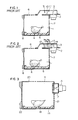
- Fig. 3 shows an embodiment of an RF heating device of the present invention.
- a wave guide l7 is used as means for coupling a rectangular heating chamber l5 formed by conductive walls to a magnetron l6 which is an RF oscillator.
- An object l8 to be heated is placed in the heating chamber l5 on a plate l9 made of a low dielectric material.
- Exhaust holes 20 for exhausting water vapor and heat generated during the heating from the device, air inlet holes 2l for supplying fresh air and a door 22 for taking in and out the object l8 are disposed in the walls of the heating chamber.
- Fig. 4 shows an enlarged perspective view of the wave guide l7 which serves as a coupler to the magnetron l6. The construction of the coupling portion will be described hereunder.
- the RF wave generated by the magnetron l6 is radiated from an output antenna 23 having a length equal to approximately l/4 of its free space wavelength ⁇ .
- the output antenna is positioned on a center axis of the cylindrical wave guide l7 having a length L and a diameter D.
- An end portion of the wave guide l7 opposite to the output antenna 23 is formed by a wall 24.
- An arcuate slit 25 which is concentric with the wave guide l7 is formed in the wall 24.
- the RF wave emitted from the output antenna 23 is transmitted through the wave guide l7 and transmitted into the heating chamber through the arcuate slit 25 which functions as a secondary radiation antenna.
- a center hole 26 is formed in the wall 24 at a portion thereof where the center axis of the wave guide passes.
- the center hole 26 serves as means for detecting any deviation of the output antenna 23 from the center axis of the wave guide l7 and also serves as means for providing the coupling between the wall 24 and a cover 27, which is provided to prevent water vapor and any material emitted from the object l8 from entering the wave guide l7 through the slit 25.
- the cover 27 is circular and completely covers the slit 25. It is made of a low dielectric material such as polypropylene, Teflon, etc. in order to avoid heating by the RF wave.
- An elastic projection 28 is inserted into the center hole 26 to fix the cover 27 to the wall 24.
- a main mode in the cylindrical wave guide which is a most stable excitation mode and which has a maximum cutoff wavelength in the cylindrical wave guide
- a main mode in the cylindrical wave guide is a circular TE11 mode which is an excitation pattern similar to TE10 which is a main mode in a rectangular wave guide
- the cutoff wavelength is related to the diameter D of the wave guide, that is, approximately, l.706 D.
- This is a condition when a wave guide length L, which is a transmission path length, is longer than ⁇ g/2 (where ⁇ g is the wavelength in the wave guide).
- the cutoff wavelength becomes longer.
- the frequency of an electromagnetic wave, which can be transmitted therethrough is lowered. Accordingly, if a small diameter is desired, the wave guide length has to be selected to be longer than ⁇ g/2.
- the excitation mode changes with the position of the output antenna 23.
- the output antenna 23 has to be positioned on the center axis of the wave guide.
- the cutoff wavelength and the main mode are applicable to the fundamental frequency.
- the wavelength becomes shorter and higher order modes such as TE21, TE31, etc. other than the main mode are apt to be generated.
- the wall current generated in the wall 24 positioned in the end plane of the cylindrical wave guide l7 may be of a pattern having several circumferential intensity variations.
- the wall current becomes minimum at the center portion of the cylindrical wave guide l7, so that the heating of the projection 28 of the cover 27 inserted into the center hole 26 can be prevented.
- the cover 27 Since the cover 27 is supported at the center hole 26, it may rotate. However, since the cover 27 is formed in a disk shape, it can completely cover the slit 25 even if it rotates. An auxiliary engaging piece (pawl) for preventing the rotation of the cover 27 may be used. In this case, since the density of the energy of the electromagnetic wave of the fundamental frequency, which is transmitted through the slit 25, is reduced at the circumferential peripheral portion thereof as compared with the center portion thereof, if the engaging piece is disposed at a portion of the circumferential periphery of the slit 25, it is possible to reduce the heating thereof.
- the wall currents generated in the wave guide walls have complex patterns depending on the excitation modes, in the case of a cylindrical wave guide, an orderly pattern can be formed in the end plane thereof.
- the arcuate slit 25 concentric with the cylindrical wave guide is perpendicular to the wall currents generated in the main mode of the fundamental wave, so that an effective radiation antenna can be obtained.
- the slit is not completely perpendicular to the wall currents generated in the higher order modes of the higher harmonic components, so that it provides a high reactance component, whereby higher harmonic components transmitted from the slit can be suppressed.
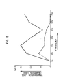
- Fig. 5 shows an experimental result which compares the performance of the RF heating device having the higher harmonic components suppression means of the present invention with that of the prior art device having no suppression means.
- a solid line shows the case of an embodiment of the present invention and a broken line shows the case of the prior art device.
- the abscissa represents a frequency
- the ordinate represents a transmission loss caused in a transmission path from the magnetron output antenna to the heating chamber.
- the loss (insertion loss) of the fundamental frequency (fo) wave is smaller, while, the loss of higher harmonic components is greater than those of the prior art device, and thus it is possible to effectively suppress higher harmonic components.
- Figs. 6a, 6b and 6c show various modifications of the slit, where the shape and the number of slits are changed.
- Variations in the effects of the suppression of the respective higher harmonic components are considered to be due to changes in the state of separation of the wall currents in the higher order modes caused by the provision of the slit 25, which changes give rise to respective reactance elements having different frequency characteristics.
- the excitation modes which are most apt to occur, differ depending on respective higher harmonic components and the frequency characteristics change depending on a position (a distance from the center) of the slit 25, a radial width and a circumferential length of the slit 25. Accordingly, a best condition for suppressing any particular higher harmonic component differs case by case.
- the radii (r1, r2) and lengths (l1, l2) of the respective center lines of two portions of the slit 25 are made to differ from each other thereby to suppress a plurality of higher harmonic components.
- any one or both of the radius and length of the slit 25 may be changed to obtain a similar result.
- Fig. 7 shows an enlarged view of another embodiment of the present invention.
- the cylindrical wave guide l7 is tapered with respect to the center axis (X - X′) of the wave guide. That is, a diameter D1 at its end side of the output antenna 23 of the magnetron l6 is made smaller than a diameter D2 at its end side of the heating chamber wall.
- the wave guide may be integrally formed by a drawing work, etc.
- the cylindrical wave guide thus integrally formed is fixed to the heating chamber wall 24 by a welding operation and so on.
- the conductive member 29 is disposed near the output antenna 23, it is possible to change the load impedance by the shape or number of the conductive member 29 or the relative position between the output antenna 23 and the conductive member 29. Accordingly, the adjustment for effecting the impedance matching between the magnetron and the heating chamber can be done without deteriorating the effect of suppressing higher harmonic components by the slit 25. Thus, it is possible to satisfy separately the two technical requirements of the suppression of higher harmonic components and the improvement of operation efficiency caused by the impedance matching.
- the RF heating device having the higher harmonic components suppression means according to the present invention can give the following advantages.
Abstract
Description
- The present invention relates to feed means of a high frequency or radio frequency (abbreviated as RF) heating device which heats an object such as food by high frequency dielectric heating, and more particularly to the prevention of leakage of higher harmonic electromagnetic wave compoents other than a fundamental frequency electromagnetic wave component used for the heating purpose.
- A frequency band permitted for use in an R.F. heating device is limited to a specific band (usually called an ISM band), although it may differ from country to country to be 9l5 MHz band, 2450 MHz band, etc. So long as there is no danger to human body and safety is assured, there is no legal regulation on the frequency band. However, an RF oscillator usually generates higher harmonic components. In a magnetron which is a microwave oscillator oscillating at a foundametal frequency (fo) of 2450 MHz, relatively high power components are generated at 4900 MHz, 7350 MHz, 9800 MHz and l2250 MHz which are integral order higher harmonic components of the fundamental frequency (those components are represented by 2fo, 3fo, 4fo and 5fo).
- Those higher harmonic components are subject to severe legal regulation in order to prevent disturbance to other communication equipments.
- Accordingly, various approaches to suppress the higher harmonic components have been made. Figs. l and 2 show schematic sectional views of prior art RF heating devices having such a kind of means. In Fig. l, a
wave guide 3 is used as means for coupling a rectangular heating chamber l formed by conductive walls to an RF oscillator 2. Anobject 4 to be heated is placed in the heating chamber on aplate 5 made of a low dielectric material. The heating chamber walls haveexhaust holes 6, through which water vapor generated from theobject 4 during the heating is exhausted, and air inlet holes 7, through which fresh air is supplied, and adoor 8 through which theobject 4 is taken in and out of the heating chamber l. - RF electromagnetic waves including higher harmonic components generated by the RF oscillator 2 is directed to the heating chamber l through the
wave guide 3. - Once the higher harmonic components are fed into the heating chamber l, they are transmitted out of the RF heating device through many paths such as the
exhaust holes 6, air inlet holes 7 and clearances between thedoor 8 and the heating chamber walls. As a result, it is difficult to design electromagnetic wave leakage prevention means to be arranged around the door. Thus, in order to attenuate the heigher harmonic components themselves of the RF wave fed into the heating chamber,conductive bars 9, l0 and ll of different lengths are mounted in thewave guide 3 to form a resonator operating as a band-pass filter in order to prevent the transmission of higher harmonic components other than the fo component into the heating chamber (Japanese Examined Utility Model Publication No. 5l-l45l4). - However, in the structure in which the
conductive bars 9, l0 and ll of different lengths are projected, the suppression frequency band is very narrow because the suppression frequency is determined by the projection length. In order to widen the suppression frequency band, the number of conductive bars may be increased. However, the conductive bars have to be spaced from each other by a predetermined distance in order to prevent electric discharge due to the concentration of RF wave energy. Accordingly, if the conductive bars are selected one for each higher harmonic component, the length of the wave guide increases and the overall construction of the device becomes complex and expensive. - In Fig. 2, conductive plates l2, l3 and l4 each thereof having a width along a center axis of the
wave guide 3 are arranged at spatial intervals of approximately λg/2, where λg is a wavelength of the fo component in the wave guide, to form a three-dimensional resonator to prevent transmission of electromagnetic waves having frequencies other than fo. However, it is difficult to dispose such three-dimensional circuit elements, which resonate only at fo, in a closed wave guide. Further, since such elements are arranged on the axis of the wave guide where the electric field strength is highest, large RF currents flow through the conductive plates and hence a loss of the fundamental frequency component increases. - It is an object of the present invention to reduce a loss of a fundamental electromagnetic wave and to attenuate higher harmonic components with a simple construction thereby to improve higher harmonic component leakage preventing performance of an RF heating device.
- In the RF heating device of the present invention, a wave guide for coupling a heating chamber, in which an object to be heated is placed, to an RF oscillator has a substantially cylindrical shape and a feed port of the wave guide for feeding the heating chamber has an arcuate slit shape.
- Generally, in the wave guide having a rectangular cross-section, the RF propagation mode in the wave guide is TE₁₀ for the fundamental wave and the electric field peak thereof becomes zero in the height direction of the wave guide. While, for the fifth higher harmonic component, the propagation modes of TE₅₀ as well as TE₅₁, TE₅₂, etc. are generated freely. This is true for the other higher harmonic components. Accordingly, the electric field distributions for the respective higher harmonic components in the wave guide are complex, which makes it difficult to attenuate higher harmonic components when using higher harmonic component suppression circuit elements. However, by using a cylindrical wave guide, a plurality of electric field distribution patterns are arranged orderly in the circumferential direction even in the case of higher harmonic propagation modes. Furthermore, since the arcuate slit functions as a large reactance element against higher harmonic components existing in the cylindrical wave guide, higher harmonic components are greatly attenuated. Besides, since the slit is located at an end portion of the wave guide, the length of the wave guide can be shortened without regard to the wavelength in the wave guide and the loss of a fundamental frequency wave used for the heating purpose is reduced.
-
- Figs. l and 2 show sectional views of prior art RF heating devices having higher harmonic component suppression means.
- Fig. 3 shows an RF heating device having higher harmonic component suppression means in accordance with an embodiment of the present invention.
- Fig. 4 shows an enlarged perspective view showing a coupling portion of the higher harmonic component suppression means.
- Fig. 5 shows an experimental result which compares the performance of the RF heating device having the higher harmonic component suppression means of the present invention with that of prior art.
- Figs. 6a, 6b and 6c show a plan view showing various modifications of the slit for use in the higher harmonic component suppression means of the present invention.
- Fig. 7 shows an enlarged perspective view showing the coupling portion of the RF heating device having the higher harmonic component suppression means of another embodiment of the present invention.
- Fig. 3 shows an embodiment of an RF heating device of the present invention.
- In Fig. 3, a wave guide l7 is used as means for coupling a rectangular heating chamber l5 formed by conductive walls to a magnetron l6 which is an RF oscillator. An object l8 to be heated is placed in the heating chamber l5 on a plate l9 made of a low dielectric material.
Exhaust holes 20 for exhausting water vapor and heat generated during the heating from the device, air inlet holes 2l for supplying fresh air and adoor 22 for taking in and out the object l8 are disposed in the walls of the heating chamber. - Fig. 4 shows an enlarged perspective view of the wave guide l7 which serves as a coupler to the magnetron l6. The construction of the coupling portion will be described hereunder.
- The RF wave generated by the magnetron l6 is radiated from an
output antenna 23 having a length equal to approximately l/4 of its free space wavelength λ. The output antenna is positioned on a center axis of the cylindrical wave guide l7 having a length L and a diameter D. An end portion of the wave guide l7 opposite to theoutput antenna 23 is formed by awall 24. Anarcuate slit 25 which is concentric with the wave guide l7 is formed in thewall 24. The RF wave emitted from theoutput antenna 23 is transmitted through the wave guide l7 and transmitted into the heating chamber through thearcuate slit 25 which functions as a secondary radiation antenna. - A
center hole 26 is formed in thewall 24 at a portion thereof where the center axis of the wave guide passes. Thecenter hole 26 serves as means for detecting any deviation of theoutput antenna 23 from the center axis of the wave guide l7 and also serves as means for providing the coupling between thewall 24 and acover 27, which is provided to prevent water vapor and any material emitted from the object l8 from entering the wave guide l7 through theslit 25. Thecover 27 is circular and completely covers theslit 25. It is made of a low dielectric material such as polypropylene, Teflon, etc. in order to avoid heating by the RF wave. Anelastic projection 28 is inserted into thecenter hole 26 to fix thecover 27 to thewall 24. - The state of the RF wave in the cylindrical wave guide is now considered. A main mode in the cylindrical wave guide, which is a most stable excitation mode and which has a maximum cutoff wavelength in the cylindrical wave guide, is a circular TE₁₁ mode which is an excitation pattern similar to TE₁₀ which is a main mode in a rectangular wave guide, and the cutoff wavelength is related to the diameter D of the wave guide, that is, approximately, l.706 D. This is a condition when a wave guide length L, which is a transmission path length, is longer than λg/2 (where λg is the wavelength in the wave guide).
- If L is shorter than λg/2, the cutoff wavelength becomes longer. Thus, if a wave guide of the same diameter is used, the frequency of an electromagnetic wave, which can be transmitted therethrough, is lowered. Accordingly, if a small diameter is desired, the wave guide length has to be selected to be longer than λg/2.
- The excitation mode changes with the position of the
output antenna 23. In order to attain stable excitation of the main circular mode TE₁₁, theoutput antenna 23 has to be positioned on the center axis of the wave guide. - All the values of the cutoff wavelength and the main mode are applicable to the fundamental frequency. For the higher harmonic components, the wavelength becomes shorter and higher order modes such as TE₂₁, TE₃₁, etc. other than the main mode are apt to be generated.
- An important factor when using a wave guide having a slit, which is used as the output antenna, is an RF wall current. If the slit is formed perpendicularly to the wall current, the wall current is separated and an effective radiation antenna is obtained.
- In any mode including the main mode of the fundamental wave and the higher order modes of the higher harmonic components generated in the cylindrical wave guide, the wall current generated in the
wall 24 positioned in the end plane of the cylindrical wave guide l7 may be of a pattern having several circumferential intensity variations. The wall current becomes minimum at the center portion of the cylindrical wave guide l7, so that the heating of theprojection 28 of thecover 27 inserted into thecenter hole 26 can be prevented. - Since the
cover 27 is supported at thecenter hole 26, it may rotate. However, since thecover 27 is formed in a disk shape, it can completely cover theslit 25 even if it rotates. An auxiliary engaging piece (pawl) for preventing the rotation of thecover 27 may be used. In this case, since the density of the energy of the electromagnetic wave of the fundamental frequency, which is transmitted through theslit 25, is reduced at the circumferential peripheral portion thereof as compared with the center portion thereof, if the engaging piece is disposed at a portion of the circumferential periphery of theslit 25, it is possible to reduce the heating thereof. - As described above, while, in a rectangular wave guide, the wall currents generated in the wave guide walls have complex patterns depending on the excitation modes, in the case of a cylindrical wave guide, an orderly pattern can be formed in the end plane thereof.
- The
arcuate slit 25 concentric with the cylindrical wave guide is perpendicular to the wall currents generated in the main mode of the fundamental wave, so that an effective radiation antenna can be obtained. On the other hand, the slit is not completely perpendicular to the wall currents generated in the higher order modes of the higher harmonic components, so that it provides a high reactance component, whereby higher harmonic components transmitted from the slit can be suppressed. Fig. 5 shows an experimental result which compares the performance of the RF heating device having the higher harmonic components suppression means of the present invention with that of the prior art device having no suppression means. - In Fig. 5, a solid line shows the case of an embodiment of the present invention and a broken line shows the case of the prior art device. The abscissa represents a frequency, and the ordinate represents a transmission loss caused in a transmission path from the magnetron output antenna to the heating chamber. As shown in Fig. 5, in the embodiment, the loss (insertion loss) of the fundamental frequency (fo) wave is smaller, while, the loss of higher harmonic components is greater than those of the prior art device, and thus it is possible to effectively suppress higher harmonic components.
- Figs. 6a, 6b and 6c show various modifications of the slit, where the shape and the number of slits are changed. By changing the shape, number and position of the
slit 25 while maintaining theslit 25 to be concentric with the cylindrical wave guide l7, it is possible to effect the impedance matching between the magnetron and the load, namely, the heating chamber including the object to be heated as well as to effect the adjustment of the device for attaining uniform heating of the object l8. - Variations in the effects of the suppression of the respective higher harmonic components are considered to be due to changes in the state of separation of the wall currents in the higher order modes caused by the provision of the
slit 25, which changes give rise to respective reactance elements having different frequency characteristics. - The excitation modes, which are most apt to occur, differ depending on respective higher harmonic components and the frequency characteristics change depending on a position (a distance from the center) of the
slit 25, a radial width and a circumferential length of theslit 25. Accordingly, a best condition for suppressing any particular higher harmonic component differs case by case. In Fig. 6a, the radii (r₁, r₂) and lengths (ℓ₁, ℓ₂) of the respective center lines of two portions of theslit 25 are made to differ from each other thereby to suppress a plurality of higher harmonic components. As shown in Figs. 6b and 6c, any one or both of the radius and length of theslit 25 may be changed to obtain a similar result. - With the above-described arrangements it is possible to provide new effects which cannot be attained only by a single slit. However, such a combination of the
slits 25 can give the similar merits of a low insertion loss for the fundamental frequency and the suppression of higher harmonic components. - Fig. 7 shows an enlarged view of another embodiment of the present invention. In Fig. 7, the cylindrical wave guide l7 is tapered with respect to the center axis (X - X′) of the wave guide. That is, a diameter D₁ at its end side of the
output antenna 23 of the magnetron l6 is made smaller than a diameter D₂ at its end side of the heating chamber wall. By making the wave guide have a tapered shape, the wave guide may be integrally formed by a drawing work, etc. The cylindrical wave guide thus integrally formed is fixed to theheating chamber wall 24 by a welding operation and so on. - When the
slit 25 is formed in theheating chamber wall 24, a portion of the wall, which otherwise would be cast away, is folded at a peripheral portion of theslit 25 maintaining a proper shape of theslit 25 thereby to protrude into the wave guide and form aconductive member 29. - Since the
conductive member 29 is disposed near theoutput antenna 23, it is possible to change the load impedance by the shape or number of theconductive member 29 or the relative position between theoutput antenna 23 and theconductive member 29. Accordingly, the adjustment for effecting the impedance matching between the magnetron and the heating chamber can be done without deteriorating the effect of suppressing higher harmonic components by theslit 25. Thus, it is possible to satisfy separately the two technical requirements of the suppression of higher harmonic components and the improvement of operation efficiency caused by the impedance matching. - The RF heating device having the higher harmonic components suppression means according to the present invention can give the following advantages.
- (l) Since the RF wave is supplied to the heating chamber through the slit formed in the end plane of the cylindrical wave guide, by making the electric field distribution and the wall current, which depend on the excitation mode in the culindrical wave guide, have respective orderly patterns, it is possible to provide a slit antenna functioning as a reactance element which gives a small insertion loss to the fundamental frequency electromagnetic wave and a great loss to higher harmonic components. Thus, it becomes possible to suppress greatly higher harmonic components.
- (2) Since the wave guide is a cylindrical wave guide, it is possible to select freely the shape, number and distribution of the slit arranged concentrically with the wave guide. Accordingly, the impedance matching and the adjustment of the heating performance may be effected independently of the adjustment of the higher harmonic components suppression means. As a result, it becomes easy to improve the efficiency of the device and the uniform heating performance.
- (3) The cylindrical wave guide can be formed as one body by drawing unlike the rectangular wave guide. Accordingly, the manufacture of the wave guide becomes easy, the working precision is elevated, the manufacturing cost is lowered, the size of the device is reduced, and the performance of the device becomes stable.
- (4) The slit formed in the wall of the heating chamber is a sole constituent element other than the cylindrical wave guide, there is required no other additional constituent member, and no component element is required in the wave guide. Accordingly, the structure of the device becomes simple, so that the manufacturing cost is reduced and it becomes possible to avoid a danger such as an electric spark occurring in the wave guide.
- (5) Since the
slit 25 and theconductive member 29 for effecting impedance matching can be formed as one body, no junction is included in the transmission path. Accordingly, the structure of the device is simple, the working precision is improved, the manufacturing cost is reduced, and the performance of the device becomes stable. - (6) Since the dielectric cover may be fixed to a portion of the wall in the end plane of the wave guide where the wall loss is low, it is possible to prevent the dielectric cover from being burnt by the high frequency heating, the dielectric cover is formed to have a disk shape so as to be able to cover the slit completely. Since the dielectric cover may be fixed only by the engagement of its center portion, high safety is assured, and the manufacturing cost is reduced.
Claims (10)
a high frequency oscillator (l6);
a heating chamber (l5) for accommodating an object (l8) to be heated;
a wave guide (l7) for coupling said high frequency oscillator to said heating chamber, said wave guide being a cylindrical wave guide;
an output antenna (23) for said high frequency oscillator disposed on a center axis of said cylindrical wave guide;
a wall (24) of said heating chamber which is coupled to said cylindrical wave guide and positioned in an end plane of said cylindrical wave guide opposite to a fixing plane of said output antenna; and
at least one arcuate slit (25) formed in said wall of said heating chamber, being centered at the center axis of said cylindrical wave guide.
a high frequency oscillator (l6);
a heating chamber (l5) for accommodating an object (l8) to be heated;
a wave guide (l7) for coupling said high frequency oscillator to said heating chamber, said wave guide being a cylindrical wave guide;
an output antenna (23) for said high frequency oscillator disposed on a center axis of said cylindrical wave guide;
a wall (24) of said heating chamber which is coupled to said cylindrical wave guide and positioned in an end plane of said cylindrical wave guide opposite to a fixing plane of said output antenna; and
at least one arcuate slit (25) centered at the center axis of said cylindrical wave guide and disposed at a position on said wall which assures that a fundamental frequency electromagnetic wave generated by said high frequency oscillator is transmitted to said heating chamber with a small loss and harmonic components of the fundamental frequency electromagnetic wave are propagated to said heating chamber with greater attenuation.
Applications Claiming Priority (2)
| Application Number | Priority Date | Filing Date | Title |
|---|---|---|---|
| JP60283414A JPS62143392A (en) | 1985-12-17 | 1985-12-17 | Radio frequency heater |
| JP283414/85 | 1985-12-17 |
Publications (3)
| Publication Number | Publication Date |
|---|---|
| EP0227397A2 true EP0227397A2 (en) | 1987-07-01 |
| EP0227397A3 EP0227397A3 (en) | 1988-01-20 |
| EP0227397B1 EP0227397B1 (en) | 1990-10-03 |
Family
ID=17665218
Family Applications (1)
| Application Number | Title | Priority Date | Filing Date |
|---|---|---|---|
| EP86309738A Expired EP0227397B1 (en) | 1985-12-17 | 1986-12-12 | High frequency heating device |
Country Status (6)
| Country | Link |
|---|---|
| US (1) | US4733037A (en) |
| EP (1) | EP0227397B1 (en) |
| JP (1) | JPS62143392A (en) |
| AU (1) | AU572038B2 (en) |
| CA (1) | CA1263713A (en) |
| DE (1) | DE3674747D1 (en) |
Cited By (3)
| Publication number | Priority date | Publication date | Assignee | Title |
|---|---|---|---|---|
| EP0373608A2 (en) * | 1988-12-14 | 1990-06-20 | Mitsubishi Denki Kabushiki Kaisha | Microwave heating apparatus |
| CN101615930B (en) * | 2009-07-28 | 2013-01-02 | 华为技术有限公司 | Microwave communication equipment, adapter and communication system |
| EP3120665B1 (en) | 2014-03-21 | 2018-01-31 | Whirlpool Corporation | Solid-state microwave device |
Families Citing this family (12)
| Publication number | Priority date | Publication date | Assignee | Title |
|---|---|---|---|---|
| SE9003012L (en) * | 1990-09-21 | 1991-09-16 | Whirlpool Int | MICROWAVE OVEN, METHOD FOR EXCITING THE CAVITY IN A MICROWAVE OVEN, AND GUIDANCE MANUAL FOR THE IMPLEMENTATION OF THE METHOD |
| KR950003782B1 (en) * | 1992-08-25 | 1995-04-18 | 주식회사금성사 | Microwave range with a two-way heating system |
| JP3019239B2 (en) * | 1992-10-28 | 2000-03-13 | 船井電機株式会社 | microwave |
| KR100200063B1 (en) * | 1995-11-10 | 1999-06-15 | 전주범 | Improved structure of microwave oven |
| KR19980063369A (en) * | 1996-12-12 | 1998-10-07 | 윤종용 | microwave |
| KR100301902B1 (en) * | 1997-11-15 | 2001-11-22 | 구자홍 | Magnetron mounting structure of microwave oven |
| JP2000277251A (en) * | 1999-03-24 | 2000-10-06 | Nara Seiki Kk | Wave guide device for heating apparatus using electromagnetic waves and plasma burner generating device using the wave guide device |
| JP3750586B2 (en) * | 2001-10-31 | 2006-03-01 | 松下電器産業株式会社 | High frequency heating device |
| JP6252820B2 (en) * | 2011-07-26 | 2017-12-27 | パナソニックIpマネジメント株式会社 | High frequency cooker |
| ITFI20130154A1 (en) * | 2013-06-28 | 2014-12-29 | Raoul Cangemi | ILLUMINATING MICROWAVE STOVE WITH ENERGY RECOVERY |
| US11052557B2 (en) * | 2016-11-04 | 2021-07-06 | Heated Blades Holding Company, Llc | Heating blades of razor using RF energy |
| DE102019128042A1 (en) * | 2019-10-17 | 2021-04-22 | Topinox Sarl | Cooking device, microwave assembly and method for operating a cooking device |
Citations (2)
| Publication number | Priority date | Publication date | Assignee | Title |
|---|---|---|---|---|
| US3209112A (en) * | 1963-05-29 | 1965-09-28 | Westinghouse Electric Corp | Oven |
| EP0198500A2 (en) * | 1985-04-17 | 1986-10-22 | Matsushita Electric Industrial Co., Ltd. | Heat cooking apparatus |
Family Cites Families (5)
| Publication number | Priority date | Publication date | Assignee | Title |
|---|---|---|---|---|
| US3789179A (en) * | 1972-04-03 | 1974-01-29 | Matsushita Electric Ind Co Ltd | Microwave oven with premixing of wave energy before delivery to its heating cavity |
| JPS5349347A (en) * | 1976-10-18 | 1978-05-04 | Hitachi Heating Appliance Co Ltd | Microwave oven |
| SE439092B (en) * | 1980-10-07 | 1985-05-28 | Philips Norden Ab | INPUT AND EQUIPMENT IN MICROWAVE OVEN |
| US4463239A (en) * | 1982-12-06 | 1984-07-31 | General Electric Company | Rotating slot antenna arrangement for microwave oven |
| US4496814A (en) * | 1983-01-10 | 1985-01-29 | General Electric Company | Microwave excitation system |
-
1985
- 1985-12-17 JP JP60283414A patent/JPS62143392A/en active Granted
-
1986
- 1986-12-12 EP EP86309738A patent/EP0227397B1/en not_active Expired
- 1986-12-12 DE DE8686309738T patent/DE3674747D1/en not_active Expired - Lifetime
- 1986-12-15 US US06/941,896 patent/US4733037A/en not_active Expired - Fee Related
- 1986-12-16 CA CA000525466A patent/CA1263713A/en not_active Expired
- 1986-12-17 AU AU66643/86A patent/AU572038B2/en not_active Ceased
Patent Citations (2)
| Publication number | Priority date | Publication date | Assignee | Title |
|---|---|---|---|---|
| US3209112A (en) * | 1963-05-29 | 1965-09-28 | Westinghouse Electric Corp | Oven |
| EP0198500A2 (en) * | 1985-04-17 | 1986-10-22 | Matsushita Electric Industrial Co., Ltd. | Heat cooking apparatus |
Cited By (4)
| Publication number | Priority date | Publication date | Assignee | Title |
|---|---|---|---|---|
| EP0373608A2 (en) * | 1988-12-14 | 1990-06-20 | Mitsubishi Denki Kabushiki Kaisha | Microwave heating apparatus |
| EP0373608A3 (en) * | 1988-12-14 | 1992-01-15 | Mitsubishi Denki Kabushiki Kaisha | Microwave heating apparatus |
| CN101615930B (en) * | 2009-07-28 | 2013-01-02 | 华为技术有限公司 | Microwave communication equipment, adapter and communication system |
| EP3120665B1 (en) | 2014-03-21 | 2018-01-31 | Whirlpool Corporation | Solid-state microwave device |
Also Published As
| Publication number | Publication date |
|---|---|
| JPH0467316B2 (en) | 1992-10-27 |
| DE3674747D1 (en) | 1990-11-08 |
| JPS62143392A (en) | 1987-06-26 |
| EP0227397A3 (en) | 1988-01-20 |
| CA1263713A (en) | 1989-12-05 |
| US4733037A (en) | 1988-03-22 |
| AU6664386A (en) | 1987-06-25 |
| EP0227397B1 (en) | 1990-10-03 |
| AU572038B2 (en) | 1988-04-28 |
Similar Documents
| Publication | Publication Date | Title |
|---|---|---|
| EP0227397A2 (en) | High frequency heating device | |
| WO1998023133A1 (en) | Method and apparatus for powering an electrodeless lamp with reduced radio frequency interference | |
| EP2887378B1 (en) | Magnetron and high-frequency heating apparatus having the same | |
| US5021713A (en) | Magnetron | |
| US4749973A (en) | Waveguide filter used in a microwave oven | |
| EP1139377B1 (en) | Magnetrons | |
| US3600711A (en) | Coaxial filter having harmonic reflective and absorptive means | |
| US4371848A (en) | Magnetron having a filter on the output probe | |
| US5469024A (en) | Leaky wall filter for use in extended interaction klystron | |
| US3454817A (en) | Coupled cavity high-frequency electron discharge device with means for reducing the q at undesired regions without overloading the q in the operating regions | |
| KR0160810B1 (en) | Magnetron device of microwave oven | |
| US4289992A (en) | Microwave device | |
| JP2001093430A (en) | Double-loop output system for magnetron | |
| JP2594316B2 (en) | Magnetron | |
| KR0165056B1 (en) | Magnetron apparatus of microwave oven | |
| US20040061562A1 (en) | Magnetron | |
| JPH09293457A (en) | Magnetron | |
| KR970003292Y1 (en) | A ferrite core structure of magnetron for a microwave oven | |
| JP4299997B2 (en) | Magnetron device | |
| JP4401886B2 (en) | High frequency package | |
| KR940006447Y1 (en) | High frequency oscillation device for electronic range | |
| KR0175838B1 (en) | Harmonic oscillation frequency generation device | |
| JPH0461474B2 (en) | ||
| KR970011495B1 (en) | High frequency oscillator | |
| CN113437515A (en) | Ion cyclotron antenna capable of changing frequency for heating |
Legal Events
| Date | Code | Title | Description |
|---|---|---|---|
| PUAI | Public reference made under article 153(3) epc to a published international application that has entered the european phase |
Free format text: ORIGINAL CODE: 0009012 |
|
| AK | Designated contracting states |
Kind code of ref document: A2 Designated state(s): DE FR GB NL SE |
|
| PUAL | Search report despatched |
Free format text: ORIGINAL CODE: 0009013 |
|
| RHK1 | Main classification (correction) |
Ipc: F24C 7/02 |
|
| AK | Designated contracting states |
Kind code of ref document: A3 Designated state(s): DE FR GB NL SE |
|
| 17P | Request for examination filed |
Effective date: 19880601 |
|
| 17Q | First examination report despatched |
Effective date: 19890426 |
|
| GRAA | (expected) grant |
Free format text: ORIGINAL CODE: 0009210 |
|
| AK | Designated contracting states |
Kind code of ref document: B1 Designated state(s): DE FR GB NL SE |
|
| REF | Corresponds to: |
Ref document number: 3674747 Country of ref document: DE Date of ref document: 19901108 |
|
| ET | Fr: translation filed | ||
| PLBE | No opposition filed within time limit |
Free format text: ORIGINAL CODE: 0009261 |
|
| STAA | Information on the status of an ep patent application or granted ep patent |
Free format text: STATUS: NO OPPOSITION FILED WITHIN TIME LIMIT |
|
| 26N | No opposition filed | ||
| PGFP | Annual fee paid to national office [announced via postgrant information from national office to epo] |
Ref country code: GB Payment date: 19941202 Year of fee payment: 9 |
|
| PGFP | Annual fee paid to national office [announced via postgrant information from national office to epo] |
Ref country code: DE Payment date: 19941208 Year of fee payment: 9 |
|
| PGFP | Annual fee paid to national office [announced via postgrant information from national office to epo] |
Ref country code: FR Payment date: 19941209 Year of fee payment: 9 |
|
| PGFP | Annual fee paid to national office [announced via postgrant information from national office to epo] |
Ref country code: SE Payment date: 19941215 Year of fee payment: 9 |
|
| EAL | Se: european patent in force in sweden |
Ref document number: 86309738.2 |
|
| PG25 | Lapsed in a contracting state [announced via postgrant information from national office to epo] |
Ref country code: GB Effective date: 19951212 |
|
| PG25 | Lapsed in a contracting state [announced via postgrant information from national office to epo] |
Ref country code: SE Effective date: 19951213 |
|
| GBPC | Gb: european patent ceased through non-payment of renewal fee |
Effective date: 19951212 |
|
| PG25 | Lapsed in a contracting state [announced via postgrant information from national office to epo] |
Ref country code: FR Effective date: 19960830 |
|
| PG25 | Lapsed in a contracting state [announced via postgrant information from national office to epo] |
Ref country code: DE Effective date: 19960903 |
|
| REG | Reference to a national code |
Ref country code: FR Ref legal event code: ST |
|
| PGFP | Annual fee paid to national office [announced via postgrant information from national office to epo] |
Ref country code: NL Payment date: 19971223 Year of fee payment: 12 |
|
| PG25 | Lapsed in a contracting state [announced via postgrant information from national office to epo] |
Ref country code: NL Free format text: LAPSE BECAUSE OF NON-PAYMENT OF DUE FEES Effective date: 19990701 |
|
| NLV4 | Nl: lapsed or anulled due to non-payment of the annual fee |
Effective date: 19990701 |