EP0373188B1 - Exhaust gas muffler arrangement for combustion engine - Google Patents
Exhaust gas muffler arrangement for combustion engine Download PDFInfo
- Publication number
- EP0373188B1 EP0373188B1 EP89902911A EP89902911A EP0373188B1 EP 0373188 B1 EP0373188 B1 EP 0373188B1 EP 89902911 A EP89902911 A EP 89902911A EP 89902911 A EP89902911 A EP 89902911A EP 0373188 B1 EP0373188 B1 EP 0373188B1
- Authority
- EP
- European Patent Office
- Prior art keywords
- noise
- exhaust pipe
- chamber
- exhaust
- speaker
- Prior art date
- Legal status (The legal status is an assumption and is not a legal conclusion. Google has not performed a legal analysis and makes no representation as to the accuracy of the status listed.)
- Expired - Lifetime
Links
Images



Classifications
-
- F—MECHANICAL ENGINEERING; LIGHTING; HEATING; WEAPONS; BLASTING
- F01—MACHINES OR ENGINES IN GENERAL; ENGINE PLANTS IN GENERAL; STEAM ENGINES
- F01N—GAS-FLOW SILENCERS OR EXHAUST APPARATUS FOR MACHINES OR ENGINES IN GENERAL; GAS-FLOW SILENCERS OR EXHAUST APPARATUS FOR INTERNAL-COMBUSTION ENGINES
- F01N1/00—Silencing apparatus characterised by method of silencing
-
- F—MECHANICAL ENGINEERING; LIGHTING; HEATING; WEAPONS; BLASTING
- F01—MACHINES OR ENGINES IN GENERAL; ENGINE PLANTS IN GENERAL; STEAM ENGINES
- F01N—GAS-FLOW SILENCERS OR EXHAUST APPARATUS FOR MACHINES OR ENGINES IN GENERAL; GAS-FLOW SILENCERS OR EXHAUST APPARATUS FOR INTERNAL-COMBUSTION ENGINES
- F01N1/00—Silencing apparatus characterised by method of silencing
- F01N1/16—Silencing apparatus characterised by method of silencing by using movable parts
- F01N1/22—Silencing apparatus characterised by method of silencing by using movable parts the parts being resilient walls
-
- F—MECHANICAL ENGINEERING; LIGHTING; HEATING; WEAPONS; BLASTING
- F01—MACHINES OR ENGINES IN GENERAL; ENGINE PLANTS IN GENERAL; STEAM ENGINES
- F01N—GAS-FLOW SILENCERS OR EXHAUST APPARATUS FOR MACHINES OR ENGINES IN GENERAL; GAS-FLOW SILENCERS OR EXHAUST APPARATUS FOR INTERNAL-COMBUSTION ENGINES
- F01N1/00—Silencing apparatus characterised by method of silencing
- F01N1/06—Silencing apparatus characterised by method of silencing by using interference effect
-
- F—MECHANICAL ENGINEERING; LIGHTING; HEATING; WEAPONS; BLASTING
- F01—MACHINES OR ENGINES IN GENERAL; ENGINE PLANTS IN GENERAL; STEAM ENGINES
- F01N—GAS-FLOW SILENCERS OR EXHAUST APPARATUS FOR MACHINES OR ENGINES IN GENERAL; GAS-FLOW SILENCERS OR EXHAUST APPARATUS FOR INTERNAL-COMBUSTION ENGINES
- F01N1/00—Silencing apparatus characterised by method of silencing
- F01N1/06—Silencing apparatus characterised by method of silencing by using interference effect
- F01N1/065—Silencing apparatus characterised by method of silencing by using interference effect by using an active noise source, e.g. speakers
-
- G—PHYSICS
- G10—MUSICAL INSTRUMENTS; ACOUSTICS
- G10K—SOUND-PRODUCING DEVICES; METHODS OR DEVICES FOR PROTECTING AGAINST, OR FOR DAMPING, NOISE OR OTHER ACOUSTIC WAVES IN GENERAL; ACOUSTICS NOT OTHERWISE PROVIDED FOR
- G10K11/00—Methods or devices for transmitting, conducting or directing sound in general; Methods or devices for protecting against, or for damping, noise or other acoustic waves in general
- G10K11/16—Methods or devices for protecting against, or for damping, noise or other acoustic waves in general
- G10K11/175—Methods or devices for protecting against, or for damping, noise or other acoustic waves in general using interference effects; Masking sound
- G10K11/178—Methods or devices for protecting against, or for damping, noise or other acoustic waves in general using interference effects; Masking sound by electro-acoustically regenerating the original acoustic waves in anti-phase
- G10K11/1785—Methods, e.g. algorithms; Devices
- G10K11/17857—Geometric disposition, e.g. placement of microphones
-
- G—PHYSICS
- G10—MUSICAL INSTRUMENTS; ACOUSTICS
- G10K—SOUND-PRODUCING DEVICES; METHODS OR DEVICES FOR PROTECTING AGAINST, OR FOR DAMPING, NOISE OR OTHER ACOUSTIC WAVES IN GENERAL; ACOUSTICS NOT OTHERWISE PROVIDED FOR
- G10K11/00—Methods or devices for transmitting, conducting or directing sound in general; Methods or devices for protecting against, or for damping, noise or other acoustic waves in general
- G10K11/16—Methods or devices for protecting against, or for damping, noise or other acoustic waves in general
- G10K11/175—Methods or devices for protecting against, or for damping, noise or other acoustic waves in general using interference effects; Masking sound
- G10K11/178—Methods or devices for protecting against, or for damping, noise or other acoustic waves in general using interference effects; Masking sound by electro-acoustically regenerating the original acoustic waves in anti-phase
- G10K11/1785—Methods, e.g. algorithms; Devices
- G10K11/17861—Methods, e.g. algorithms; Devices using additional means for damping sound, e.g. using sound absorbing panels
-
- G—PHYSICS
- G10—MUSICAL INSTRUMENTS; ACOUSTICS
- G10K—SOUND-PRODUCING DEVICES; METHODS OR DEVICES FOR PROTECTING AGAINST, OR FOR DAMPING, NOISE OR OTHER ACOUSTIC WAVES IN GENERAL; ACOUSTICS NOT OTHERWISE PROVIDED FOR
- G10K11/00—Methods or devices for transmitting, conducting or directing sound in general; Methods or devices for protecting against, or for damping, noise or other acoustic waves in general
- G10K11/16—Methods or devices for protecting against, or for damping, noise or other acoustic waves in general
- G10K11/175—Methods or devices for protecting against, or for damping, noise or other acoustic waves in general using interference effects; Masking sound
- G10K11/178—Methods or devices for protecting against, or for damping, noise or other acoustic waves in general using interference effects; Masking sound by electro-acoustically regenerating the original acoustic waves in anti-phase
- G10K11/1787—General system configurations
- G10K11/17879—General system configurations using both a reference signal and an error signal
- G10K11/17881—General system configurations using both a reference signal and an error signal the reference signal being an acoustic signal, e.g. recorded with a microphone
-
- G—PHYSICS
- G10—MUSICAL INSTRUMENTS; ACOUSTICS
- G10K—SOUND-PRODUCING DEVICES; METHODS OR DEVICES FOR PROTECTING AGAINST, OR FOR DAMPING, NOISE OR OTHER ACOUSTIC WAVES IN GENERAL; ACOUSTICS NOT OTHERWISE PROVIDED FOR
- G10K11/00—Methods or devices for transmitting, conducting or directing sound in general; Methods or devices for protecting against, or for damping, noise or other acoustic waves in general
- G10K11/16—Methods or devices for protecting against, or for damping, noise or other acoustic waves in general
- G10K11/175—Methods or devices for protecting against, or for damping, noise or other acoustic waves in general using interference effects; Masking sound
- G10K11/178—Methods or devices for protecting against, or for damping, noise or other acoustic waves in general using interference effects; Masking sound by electro-acoustically regenerating the original acoustic waves in anti-phase
- G10K11/1787—General system configurations
- G10K11/17879—General system configurations using both a reference signal and an error signal
- G10K11/17883—General system configurations using both a reference signal and an error signal the reference signal being derived from a machine operating condition, e.g. engine RPM or vehicle speed
-
- G—PHYSICS
- G10—MUSICAL INSTRUMENTS; ACOUSTICS
- G10K—SOUND-PRODUCING DEVICES; METHODS OR DEVICES FOR PROTECTING AGAINST, OR FOR DAMPING, NOISE OR OTHER ACOUSTIC WAVES IN GENERAL; ACOUSTICS NOT OTHERWISE PROVIDED FOR
- G10K2210/00—Details of active noise control [ANC] covered by G10K11/178 but not provided for in any of its subgroups
- G10K2210/10—Applications
- G10K2210/128—Vehicles
- G10K2210/1282—Automobiles
- G10K2210/12822—Exhaust pipes or mufflers
-
- G—PHYSICS
- G10—MUSICAL INSTRUMENTS; ACOUSTICS
- G10K—SOUND-PRODUCING DEVICES; METHODS OR DEVICES FOR PROTECTING AGAINST, OR FOR DAMPING, NOISE OR OTHER ACOUSTIC WAVES IN GENERAL; ACOUSTICS NOT OTHERWISE PROVIDED FOR
- G10K2210/00—Details of active noise control [ANC] covered by G10K11/178 but not provided for in any of its subgroups
- G10K2210/30—Means
- G10K2210/321—Physical
- G10K2210/3227—Resonators
-
- G—PHYSICS
- G10—MUSICAL INSTRUMENTS; ACOUSTICS
- G10K—SOUND-PRODUCING DEVICES; METHODS OR DEVICES FOR PROTECTING AGAINST, OR FOR DAMPING, NOISE OR OTHER ACOUSTIC WAVES IN GENERAL; ACOUSTICS NOT OTHERWISE PROVIDED FOR
- G10K2210/00—Details of active noise control [ANC] covered by G10K11/178 but not provided for in any of its subgroups
- G10K2210/30—Means
- G10K2210/321—Physical
- G10K2210/3227—Resonators
- G10K2210/32272—Helmholtz resonators
Definitions
- the invention is related to an exhaust gas muffler arrangement according to the introductory part of claim 1.
- passive systems for suppressing noise at the intake and/or exhaust of gas movement systems have been proposed previously.
- passive systems use sound insulating material and/or baffles to suppress sound waves before they reach the surrounding atmosphere.
- passive systems such as conventional automotive exhaust gas mufflers, inherently restrict the exhaust gas flow, thereby resulting in energy losses with reductions in the efficiency of operation of the vehicle combustion engines.
- reduction or removal of the exhaust gas restriction back pressure substantially improves the performance of the engine.
- permitting such "straight pipe" operation of automotive vehicles results in sound patterns in public places that are not only unpleasant, they are unhealthy.
- Patent 4,473,906 to Wannaka disclose additional methods for active noise cancellation in building system air ducts or exhaust pipes in which the cancelling noise generator (speaker) is required to be exposed directly to the exhaust gas stream.
- the cancelling noise generator noise generator
- Those systems requiring placement of the speakers in the exhaust gas stream generating the undesirable sound to be cancelled place the speakers in such a harsh chemical and heat environment that they cannot operate over an extended period of time, at least not without inordinate costs for insulating the speaker and/or designing them to withstand the loud environment. Further, such placement restricts the flow of exhaust gases to some extent, thereby resulting in the above-mentioned disadvantages regarding the back pressure on the combustion engine.
- An improved active noise cancellation system is known from 306 The Motor Ship 68 (1987) Sept., No. 806, Sutton, Surrey, Great Britain, which is compatible with the operating condition of motor vehicle, combustion engine exhaust systems.
- loudspeakers are controlled by a digital controller which has inputs from a synchronizing sensor monitoring the engine rotational speed and from a residual noise sensing microphone which picks up the sound at the outlet of the exhaust pipe.
- the loudspeakers are arranged in an anti-noise chamber which asymmetrically surrounds the exhaust pipe and extends beyond the outlet opening of the exhaust pipe.
- the loudspeaker means are mounted on a radial wall of the anti-noise chamber.
- a further active noise cancellation system compatible with the operating condition of a motor vehicle combustion engine is known from JP-A 60-22010.
- the anti-speaker means is controlled by means of a control unit which processes a signal depending on the rotational speed of the engine only.
- the exhaust pipe for communicating exhaust gases to the atmosphere is surrounded by an anti-noise chamber opening to the atmosphere at a position substantially in the same plane as the exhaust pipe outlet opening.
- the anti-noise speaker means for generating anti-noise sound waves is mounted within the vehicle body and coupled to the anti-noise chamber by a heat resistant rubber bellows. The bellows is intended to compensate relative movements between the vehicle body and the anti-noise chamber fixed to the exhaust pipe.
- the anti-noise speaker means open into the anti-noise chamber which is totally isolated from the exhaust pipe and thereby the speakers are not subjected to the harsh chemical and heat environment of the exhaust gases. Also, the acoustic impedance of the system is constant.
- preferred embodiments descrbied involve vehicle combustion engine exhaust systems
- preferred embodiments of the invention are also contemplated for engine intake systems, for compressors and pumps with undesirable sound waves propagated in a pipe exhausting to atmosphere, and the like.
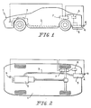
- FIGS 1 and 2 schematically depict respective side views and bottom views of a passenger motor vehicle having an active digital muffler system constructed according to preferred embodiments of the present invention.
- the system depicted in Figures 1 and 2 corresponds to the Figure 10 embodiment of the overall system (described in more detail below).
- the passenger vehicle 1 includes a multi-cylinder/piston internal combustion engine 2, the exhaust of which is transported by exhaust pipe system 3 to the exhaust outlet 4 at the rear of the vehicle.
- the rear portion of the exhaust pipe system 3 is depicted as a single exhaust pipe in the following description, although similar duplicate arrangements can be provided for dual exhaust pipe systems, is provided at its rear end with a surrounding anti-noise chamber arrangement 5, which includes anti-noise speakers driven by a power amplifier 6 and digital controller 7.
- the digital controller 7 has input signals from a residual sensing microphone 8 adjacent the exhaust outlet 4 and a synchronization sensor 9, such as a tachometer at the drive shaft of the engine 2.
- FIGs 3 and 4 schematically depict a preferred embodiment of an active digital muffler system according to the invention installed on a motor boat 1A, which, in a similar manner as the passenger motor vehicle of Figures 1 and 2, includes a reciprocating piston multi-cylinder internal combustion engine 2A, an exhaust pipe system 3A with an outlet 4A.
- An anti-noise chamber arrangement 5A is provided adjacent the downstream end of the exhaust pipe system 3 and includes speakers driven by a power amplifier 6A and controlled by a digital controller 7A.
- the digital controller 7A is in turn supplied with input signals from a residual sensor microphone 8A, the exhaust outlet of the boat motor and a synchronization sensor 9A of the output drive shaft of the boat motor engine 2.
- Certain embodiments for use with boats will include water supplied exhaust system cooling arrangements, such as water flow directly into the exhaust pipe and water flow in an annular jacket surrounding the exhaust such cooling arrangement being well known in the motor boat industry.
- FIGs 5-7 Schematically depict a first preferred embodiment of an anti-noise chamber arrangement 5 and exhaust pipe.
- Chamber 5 of Figures 6-7 is constructed as an intergal sheet metal structure and includes a centrally disposed cylindrical exhaust pipe 10 which is connected to the exhaust pipe system 3, 3A (compare Figures 1 to 4).
- the left hand end of the exhaust pipe section 10 is preferably configured so as to be insertable into an existing exhaust pipe of an engine exhaust system 3,3A, with an appropriate sealing clamping connection being provided.
- An anti-noise chamber 11 is provided in annular surrounding relationship to the exhaust pipe 10.
- the anti-noise-chamber 11 is defined by first cylindrical section 12 of a large diameter and an adjoining smaller diameter section 13.
- the left hand end of the large diameter section 12 is closed off by an annular end plate 14 which is supported at the outer surface of the exhaust pipe 10 by welding connection.
- the opposite end of the anti-noise chamber 11 is supported by radially extending support plates 15 attached by welding at the exhaust pipe 10 and by welding at the section 13 of the anti-noise chamber 11.
- a pair of cylindrical speaker support sections 17 are connected by a welding connection 18 to the cylindrical section 12 at a position adjacent the end cap 14.
- the cylindrical speaker support sections 17 have a slightly smaller diameter than the diameter of the section 12 of the anti-noise chamber and are there joined by welding seams 18. These anti-noise speaker support cylinder sections 17 are disposed symmetrically with respect to the longitudinal axis of the exhaust pipe 10 and anti-noise chamber 11. Anti-noise speakers 19 are mounted in each of the respective support section 17 and are disposed to generate sound waves emenating into the anti-noise chamber 11.
- the anti-noise chamber 11 is concentric and separate from the exhaust pipe 10, with the anti-noise sound waves generated by the speaker 19 and propagated along the length of the chamber 11 opening into the atmosphere at the same exit plane 4B as the exhaust gases from the exhaust pipe 10.
- the manufacture of the anti-noise muffler chamber arrangement is quite simple and it can be constructed as a unit that can be added on to an existing exhaust system 3 merely by connecting the left hand end of the pipe section 10 to the exhaust pipe of a vehicle.
- the exhaust pipe 10 and the cylindrical sections 12, 13 making up the anti-noise chamber 11 and the speaker supports 17 are all constructed of metal that can be easily welded together, thus further simplifying the manufacturing operation.
- Embodiments are also contemplated with a heat insulating connection at the exhaust pipe 10 such as an annular heat insulating material ring surrounding the pipe 10 which limits the transfer of heat to the components.
- a heat insulating connection at the exhaust pipe 10 such as an annular heat insulating material ring surrounding the pipe 10 which limits the transfer of heat to the components.
- the speakers 19 are disposed symmetrically with respect to the noise generating exhaust pipe 10, an especially efficient utilization of space and cancellation of noise is provided since there is symmetrical disposition of the anti-noise waves around the annular space at the outlet end plane 4B of the muffler pipe arrangement. Since the noise cancelling sound waves emanate in substantially the same plane 4B of the exhaust gases, the anti-sound wave propagation is symmetrical with the sound wave propagation from the exhaust pipe outlet, thereby simplifying the construction and operation.
- the speakers 19 are also isolated by chamber 11 from the exhaust gases and thereby do not have to withstand the highly corrosive hot gases in the exhaust stream.
- the dimensions are as follows referring to Figure 6: diameter 2D of the exhaust pipe 10 is 5,715 cm (2.250 inches) inside diameter, the length 71 between end plate 14 and the left end of the pipe 10 is 5,08 cm (2 inches), the radial width 11R of the chamber section 12 outside of the pipe 10 is 4,45 cm (1.75 inches), the radial width 15R between the outside of the pipe 10 and the outer wall of cylindrical section 13 is 1,9 cm (0.75 inches), the radial length 17R of the speaker support sections 17 is 6,35 cm (2.5 inches), the diameter 17D of the cylindrical sections 17 is 12,7 cm (5 inches), the distance 12L between the edge of the sections 17 and the end of chamber section 12 is 12,07 cm (4.75 inches), and the length 13L of the section 13 is 12,7 cm (5 inches).
- FIG. 8 and 9 is the same as the embodiment of Figures 5 through 7 described above, except for the addition of an intermediate low pressure cooling exhaust gas chamber 20 between the anti-noise chamber 11A and the exhaust pipe.
- like reference numerals with a suffix A will be included to designate corresponding structure from the embodiment of Figures 5 through 8. These structures are described only to the extent that they function differently from the corresponding structure embodiment of Figures 5 and 8.
- the annular intermediate chamber 20 is communicated with the exhaust pipe 10A by eight radially extending 1/8 inch diameter holes 21 in the pipe 10A.
- the holes 21 are disposed at the upstream end of the anti-noise chamber 11 and allow a small amount of cooling air to be sucked in by the exhaust gas flow through the opening at end plane 4B so cooling air flows in chamber 20 counter to the direction of flow of the exhaust gases and then into the exhaust pipe.
- the radially extending reinforcing plates 15 extend also through the end portion of this chamber 20 and support the respective concentric pipes forming same.
- the cooling air flow communicated to the exhaust pipe through openings 21 also aid in reducing the turbulence of the exhaust gases that exit from the exhaust pipe 10A and thereby further reduce over all noise levels.
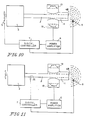
- FIG 10 schematically depicts a first embodiment of a control system for the active digital muffler system of the present invention.
- a synchronization sensor such as an engine tachometer 9 provides synchronization signal inputs to a digital controller 7 which is also supplied by a residual sensor microphone 8 which picks up the actual sound wave pattern downstream of the outlet plane 4B of the exhaust pipe 10 and the anti-noise chamber 11 the controller 7 controls power amplifier 6 which in turn drives the speakers 19 to generate the noise-cancelling waves in the chamber 11, which then travel to the outlet plane 4B of the exhaust pipe 10 and effect cancellation of the sound waves emenating from the pipe outlet.
- the audio power amplifier 6 is integrated with the digital electronic controller 7.
- the digital controller can utilize a frequency domain alogorithm as described in U.S. Patent 4,490,841 by Chaplin.
- the digital controller can utilize a time domain alogorithm as described in co-inventor Eldon Ziegler, Jr.'s pending U.S. Patent Application Serial No. 238,188 filed on August 30, 1988.
- a practical speaker and microphone usable with a configuration as in Figures 5-7 or 8 and 9 has the following characteristics.
- FIG. 11 A second control system for the active digital muffler system is schematically depicted in Figure 11. Since the Figure 11 system only differs from the Figure 10 system in the utilization of an upstream sensor microphone 22, in lieu of the tachometer synchronizing sensor 9, the remaining structure is depicted by similar reference numerals as in Figure 10. Similarly to the Figure 10 embodiment, either of a frequency domain alogorithm controller or a time domain alogorithm controller can be utilized. The difference between the Figure 10 and 11 embodiment being that the input from microphone 22 is utilized instead of the input from a tachometer sensor 9 as in Figure 10.
- controller 7 a controller corresponding to the NCT 20C0 controller marketed by Noise Cancellation Technologies Inc., can be used to serve as controller 7.
- Figure 12 is a graphical comparison showing a dramatic reduction in noise levels utilizing the active digital muffler system on a diesel engine, as compared with operating the same diesel engine without cancellation.
- the upper graph shows the noise levels without cancellation and the lower graph shows the noise levels with cancellation.
- the following is a Table of the experimental results shown on the Figure 12 graph.
- the passive muffler can be deleted from the vehicle exhaust pipe system. Deletion of the passive muffler (so-called "straight pipe” operations) results in remarkable increases in engine efficiency and power, as is known to those skilled in the art of automotive internal combustion engines.
Landscapes
- Engineering & Computer Science (AREA)
- Physics & Mathematics (AREA)
- Acoustics & Sound (AREA)
- Multimedia (AREA)
- Chemical & Material Sciences (AREA)
- Combustion & Propulsion (AREA)
- Mechanical Engineering (AREA)
- General Engineering & Computer Science (AREA)
- Exhaust Silencers (AREA)
- Soundproofing, Sound Blocking, And Sound Damping (AREA)
Abstract
Description
- The invention is related to an exhaust gas muffler arrangement according to the introductory part of
claim 1. - Numerous passive systems for suppressing noise at the intake and/or exhaust of gas movement systems have been proposed previously. Such passive systems use sound insulating material and/or baffles to suppress sound waves before they reach the surrounding atmosphere. These so-called "passive systems", such as conventional automotive exhaust gas mufflers, inherently restrict the exhaust gas flow, thereby resulting in energy losses with reductions in the efficiency of operation of the vehicle combustion engines. It is well known to those skilled in the art of internal combustion engines that reduction or removal of the exhaust gas restriction back pressure substantially improves the performance of the engine. However, permitting such "straight pipe" operation of automotive vehicles results in sound patterns in public places that are not only unpleasant, they are unhealthy. For these reasons, virtually every industrialized nation has restrictions on the level of noise propagation that can be generated by automotive vehicles and other machinery operating in public places. To date, in order to satisfy these noise abatement restrictions, virtually all automotive vehicles have relied on the passive muffler systems with consequent reduction in engine efficiency. Coupled with the reduction in engine efficiency there is of course inherent increased pollution due to increased hydrocarbon fuel consumption.
- So-called "active" noise-cancellation systems have been proposed in the past and adapted to certain environments on a small scale, usually environments involving relatively constant frequency sound generation pattern of the type that might be experienced in a fixed combustion engine constant velocity operating for a generator station or the like. U.S. Patents 4,122,303; 4,489,441; and 4,527,282 to Chaplin et al. disclose various aspects of active noise cancellation systems. French Patent 1,190,317 to Sherrer; U.S. Patents 4,677,676 and 4,677,677 to Eriksson, and U.S. Patent 4,473,906 to Wannaka disclose additional methods for active noise cancellation in building system air ducts or exhaust pipes in which the cancelling noise generator (speaker) is required to be exposed directly to the exhaust gas stream. Those systems requiring placement of the speakers in the exhaust gas stream generating the undesirable sound to be cancelled place the speakers in such a harsh chemical and heat environment that they cannot operate over an extended period of time, at least not without inordinate costs for insulating the speaker and/or designing them to withstand the loud environment. Further, such placement restricts the flow of exhaust gases to some extent, thereby resulting in the above-mentioned disadvantages regarding the back pressure on the combustion engine. Furthermore, those prior art systems that have been utilized in exhaust environments do not exhibit the compactness to facilitate commercialization and use on automotive and marine passenger vehicles and also do not have control systems that are responsive to the varying noise spectrum generated during the normal driving of such vehicles, with acceleration and deceleration over a wide range of vehicle engine speeds.
- An improved active noise cancellation system is known from 306 The Motor Ship 68 (1987) Sept., No. 806, Sutton, Surrey, Great Britain, which is compatible with the operating condition of motor vehicle, combustion engine exhaust systems. In that only schematically disclosed system loudspeakers are controlled by a digital controller which has inputs from a synchronizing sensor monitoring the engine rotational speed and from a residual noise sensing microphone which picks up the sound at the outlet of the exhaust pipe. The loudspeakers are arranged in an anti-noise chamber which asymmetrically surrounds the exhaust pipe and extends beyond the outlet opening of the exhaust pipe. The loudspeaker means are mounted on a radial wall of the anti-noise chamber.
- A further active noise cancellation system compatible with the operating condition of a motor vehicle combustion engine is known from JP-A 60-22010. The anti-speaker means is controlled by means of a control unit which processes a signal depending on the rotational speed of the engine only. The exhaust pipe for communicating exhaust gases to the atmosphere is surrounded by an anti-noise chamber opening to the atmosphere at a position substantially in the same plane as the exhaust pipe outlet opening. The anti-noise speaker means for generating anti-noise sound waves is mounted within the vehicle body and coupled to the anti-noise chamber by a heat resistant rubber bellows. The bellows is intended to compensate relative movements between the vehicle body and the anti-noise chamber fixed to the exhaust pipe. Such compensation of movements will cause the bellows to flex and to elongate and to contract its length. This change of length of the bellows changes the acoustic impedance of the system and thus also the tuning frequency and the efficiency of the transfer of the cancelling signal.
- It is object of the present invention to provide an exhaust gas muffler arrangement for active noise cancellation systems of combustion engines which is compact and economical to manufacture and which can be incorporated into mass production vehicles with a consequent substantial reduction of the overall costs of operating such vehicles as compared with vehicles having conventional passive muffler systems.
- This object is achieved by the features of
claim 1. - The anti-noise speaker means open into the anti-noise chamber which is totally isolated from the exhaust pipe and thereby the speakers are not subjected to the harsh chemical and heat environment of the exhaust gases. Also, the acoustic impedance of the system is constant.
- Although the preferred embodiments descrbied involve vehicle combustion engine exhaust systems, preferred embodiments of the invention are also contemplated for engine intake systems, for compressors and pumps with undesirable sound waves propagated in a pipe exhausting to atmosphere, and the like.
- Other objects, advantages and novel features of the present invention will become apparent from the following detailed description of the invention when considered in conjunction with the accompanying drawings.
- Figure 1 is a schematic side view of a passenger vehicle depicting the location of the engine exhaust system and a digital muffler system;
- Figure 2 is a schematic bottom view of the vehicle of Figure 1 depicting the vehicle exhaust system and active digital muffler system;
- Figure 3 is a side schematic view of a motor boat equipped with an active digital muffler system;
- Figure 4 is a schematic view showing the engine, exhaust system and active digital muffler system for use with the boat of Figure 3;
- Figure 5 is a schematic perspective view of an exhaust muffler arrangement constructed according to a preferred embodiment of the present invention;
- Figure 6 is a longitudinal section view of the muffler arrangement of Figure 5;
- Figure 7 is an end view taken from the right side of Figure 6;
- Figure 8 is a view similar to Figure 6, showing an alternative of the exhaust muffler arrangement of the present invention, having an intermediate exhaust gas low pressure cooling chamber;
- Figure 9 is an end view from the right side of Figure 8;
- Figure 10 is a schematic depiction of a complete active digital muffler system constructed according to a preferred embodiment of the present invention;
- Figure 11 is a schematic depiction of a complete active digital muffler system constructed according to another preferred embodiment of the present invention;
- Figure 12 is a graph comparing test results on a vehicle with a diesel engine, showing the sound spectrum at the exhaust with and without noise attenuation using the system of the present invention.
- Figures 1 and 2 schematically depict respective side views and bottom views of a passenger motor vehicle having an active digital muffler system constructed according to preferred embodiments of the present invention. The system depicted in Figures 1 and 2 corresponds to the Figure 10 embodiment of the overall system (described in more detail below). The
passenger vehicle 1 includes a multi-cylinder/pistoninternal combustion engine 2, the exhaust of which is transported byexhaust pipe system 3 to theexhaust outlet 4 at the rear of the vehicle. The rear portion of theexhaust pipe system 3, is depicted as a single exhaust pipe in the following description, although similar duplicate arrangements can be provided for dual exhaust pipe systems, is provided at its rear end with a surroundinganti-noise chamber arrangement 5, which includes anti-noise speakers driven by apower amplifier 6 anddigital controller 7. Thedigital controller 7 has input signals from aresidual sensing microphone 8 adjacent theexhaust outlet 4 and asynchronization sensor 9, such as a tachometer at the drive shaft of theengine 2. - Figures 3 and 4 schematically depict a preferred embodiment of an active digital muffler system according to the invention installed on a
motor boat 1A, which, in a similar manner as the passenger motor vehicle of Figures 1 and 2, includes a reciprocating piston multi-cylinderinternal combustion engine 2A, anexhaust pipe system 3A with an outlet 4A. Ananti-noise chamber arrangement 5A is provided adjacent the downstream end of theexhaust pipe system 3 and includes speakers driven by apower amplifier 6A and controlled by adigital controller 7A. Thedigital controller 7A is in turn supplied with input signals from aresidual sensor microphone 8A, the exhaust outlet of the boat motor and asynchronization sensor 9A of the output drive shaft of theboat motor engine 2. Certain embodiments for use with boats will include water supplied exhaust system cooling arrangements, such as water flow directly into the exhaust pipe and water flow in an annular jacket surrounding the exhaust such cooling arrangement being well known in the motor boat industry. - The following description of the details of the anti-noise chamber arrangement surrounding the exhaust pipe and the controller circuit for controlling the same is similar for the embodiments for both the over the road passenger motor vehicles of Figures 1 and 2 and the motor boat of Figures 3 and 4. It will be understood by those skilled in the art that certain components in the motor boat environment need to be "marine" qualified to withstand salt sea air and the like.
- Figures 5-7 Schematically depict a first preferred embodiment of an
anti-noise chamber arrangement 5 and exhaust pipe.Chamber 5 of Figures 6-7 is constructed as an intergal sheet metal structure and includes a centrally disposedcylindrical exhaust pipe 10 which is connected to theexhaust pipe system exhaust pipe section 10 is preferably configured so as to be insertable into an existing exhaust pipe of anengine exhaust system - An anti-noise chamber 11 is provided in annular surrounding relationship to the
exhaust pipe 10. The anti-noise-chamber 11 is defined by firstcylindrical section 12 of a large diameter and an adjoiningsmaller diameter section 13. The left hand end of thelarge diameter section 12 is closed off by anannular end plate 14 which is supported at the outer surface of theexhaust pipe 10 by welding connection. The opposite end of the anti-noise chamber 11 is supported by radially extendingsupport plates 15 attached by welding at theexhaust pipe 10 and by welding at thesection 13 of the anti-noise chamber 11. A pair of cylindricalspeaker support sections 17 are connected by awelding connection 18 to thecylindrical section 12 at a position adjacent theend cap 14. In the illustrated embodiment the cylindricalspeaker support sections 17 have a slightly smaller diameter than the diameter of thesection 12 of the anti-noise chamber and are there joined bywelding seams 18. These anti-noise speakersupport cylinder sections 17 are disposed symmetrically with respect to the longitudinal axis of theexhaust pipe 10 and anti-noise chamber 11.Anti-noise speakers 19 are mounted in each of therespective support section 17 and are disposed to generate sound waves emenating into the anti-noise chamber 11. The anti-noise chamber 11 is concentric and separate from theexhaust pipe 10, with the anti-noise sound waves generated by thespeaker 19 and propagated along the length of the chamber 11 opening into the atmosphere at thesame exit plane 4B as the exhaust gases from theexhaust pipe 10. - By arranging the
speakers 19 to be symmetrical with the longitudinal axis of theexhaust pipe 10 and by providing the anti-noise chamber 11 as an annular chamber surrounding thepipe 10, the manufacture of the anti-noise muffler chamber arrangement is quite simple and it can be constructed as a unit that can be added on to an existingexhaust system 3 merely by connecting the left hand end of thepipe section 10 to the exhaust pipe of a vehicle. In especially preferred embodiments, theexhaust pipe 10 and thecylindrical sections exhaust pipe 10 such as an annular heat insulating material ring surrounding thepipe 10 which limits the transfer of heat to the components. Since thespeakers 19 are disposed symmetrically with respect to the noise generatingexhaust pipe 10, an especially efficient utilization of space and cancellation of noise is provided since there is symmetrical disposition of the anti-noise waves around the annular space at theoutlet end plane 4B of the muffler pipe arrangement. Since the noise cancelling sound waves emanate in substantially thesame plane 4B of the exhaust gases, the anti-sound wave propagation is symmetrical with the sound wave propagation from the exhaust pipe outlet, thereby simplifying the construction and operation. Thespeakers 19 are also isolated by chamber 11 from the exhaust gases and thereby do not have to withstand the highly corrosive hot gases in the exhaust stream. - Other preferred embodiments are contemplated which utilize only a single speaker opening into the acoustically tuned chamber 11, the annular outlet at
plane 4B effectively providing an appropriate effective common point source for the cancelling and undesired sound. The additional speakers of the preferred embodiments illustrated facilitate the use of smaller speakers for the same output, thus economizing space. - In an especially preferred practical embodiment, the dimensions are as follows referring to Figure 6:
diameter 2D of theexhaust pipe 10 is 5,715 cm (2.250 inches) inside diameter,
the length 71 betweenend plate 14 and the left end of thepipe 10 is 5,08 cm (2 inches),
the radial width 11R of thechamber section 12 outside of thepipe 10 is 4,45 cm (1.75 inches),
theradial width 15R between the outside of thepipe 10 and the outer wall ofcylindrical section 13 is 1,9 cm (0.75 inches),
theradial length 17R of thespeaker support sections 17 is 6,35 cm (2.5 inches),
thediameter 17D of thecylindrical sections 17 is 12,7 cm (5 inches),
thedistance 12L between the edge of thesections 17 and the end ofchamber section 12 is 12,07 cm (4.75 inches),
and the length 13L of thesection 13 is 12,7 cm (5 inches). - The embodiment of Figures 8 and 9 is the same as the embodiment of Figures 5 through 7 described above, except for the addition of an intermediate low pressure cooling
exhaust gas chamber 20 between the anti-noise chamber 11A and the exhaust pipe. In Figures 8 and 9, like reference numerals with a suffix A will be included to designate corresponding structure from the embodiment of Figures 5 through 8. These structures are described only to the extent that they function differently from the corresponding structure embodiment of Figures 5 and 8. The annularintermediate chamber 20 is communicated with the exhaust pipe 10A by eight radially extending 1/8 inch diameter holes 21 in the pipe 10A. Theholes 21 are disposed at the upstream end of the anti-noise chamber 11 and allow a small amount of cooling air to be sucked in by the exhaust gas flow through the opening atend plane 4B so cooling air flows inchamber 20 counter to the direction of flow of the exhaust gases and then into the exhaust pipe. The radially extending reinforcingplates 15 extend also through the end portion of thischamber 20 and support the respective concentric pipes forming same. The cooling air flow communicated to the exhaust pipe throughopenings 21 also aid in reducing the turbulence of the exhaust gases that exit from the exhaust pipe 10A and thereby further reduce over all noise levels. - Figure 10 schematically depicts a first embodiment of a control system for the active digital muffler system of the present invention. A synchronization sensor such as an
engine tachometer 9 provides synchronization signal inputs to adigital controller 7 which is also supplied by aresidual sensor microphone 8 which picks up the actual sound wave pattern downstream of theoutlet plane 4B of theexhaust pipe 10 and the anti-noise chamber 11 thecontroller 7 controlspower amplifier 6 which in turn drives thespeakers 19 to generate the noise-cancelling waves in the chamber 11, which then travel to theoutlet plane 4B of theexhaust pipe 10 and effect cancellation of the sound waves emenating from the pipe outlet. In especially preferred embodiments, theaudio power amplifier 6 is integrated with the digitalelectronic controller 7. The digital controller can utilize a frequency domain alogorithm as described in U.S. Patent 4,490,841 by Chaplin. Alternatively, the digital controller can utilize a time domain alogorithm as described in co-inventor Eldon Ziegler, Jr.'s pending U.S. Patent Application Serial No. 238,188 filed on August 30, 1988. - A practical speaker and microphone usable with a configuration as in Figures 5-7 or 8 and 9 has the following characteristics.
- MAGNET FLUX DENSITY 11,000 GAUSS
TOTAL FLUX - 58,000 MAXWELLS
SENSITIVITY 96dB spc@ 1m, 11.2 v RMS
THEIL-SMALL PARAMETERS
SD = 92 cm²
MD = 9.8 gm
XD = 6 mm peak to peak
fs = 37 HZ
Rms = 1Ω
Cms = 1.8 x 10⁻³ M/N
VAS = 23.6 liters
QM = 2.44
QE = 0.38
QT = 0.33
IMPEDANCE 8 Ω
RANGE 55 HZ to 3,500 HZ
NET WEIGHT 1.13 kg. -
FREQ. RESPONSE 20 - 13,000 HZ IMPEDANCE 600 SENSITIVITY -71dB ± 5dB (REF OJB = 1v/µ bar, 1KHZ) POWER 1.5 VDC to 20 VDC- - A second control system for the active digital muffler system is schematically depicted in Figure 11. Since the Figure 11 system only differs from the Figure 10 system in the utilization of an
upstream sensor microphone 22, in lieu of thetachometer synchronizing sensor 9, the remaining structure is depicted by similar reference numerals as in Figure 10. Similarly to the Figure 10 embodiment, either of a frequency domain alogorithm controller or a time domain alogorithm controller can be utilized. The difference between the Figure 10 and 11 embodiment being that the input frommicrophone 22 is utilized instead of the input from atachometer sensor 9 as in Figure 10. - It is further noted that a controller corresponding to the NCT 20C0 controller marketed by Noise Cancellation Technologies Inc., can be used to serve as
controller 7. - Figure 12 is a graphical comparison showing a dramatic reduction in noise levels utilizing the active digital muffler system on a diesel engine, as compared with operating the same diesel engine without cancellation. In Figure 12 the upper graph shows the noise levels without cancellation and the lower graph shows the noise levels with cancellation. The following is a Table of the experimental results shown on the Figure 12 graph.
MARK LIST X Y(U) Y(L) 0 90.000 -18.0 -44.5 1 104.99 -45.3 -51.8 2 120.00 -45.9 -53.4 3 135.00 -41.8 -59.7 4 150.00 -38.3 -60.3 5 165.00 -45.9 -56.0 6 180.00 -24.8 -49.4 7 240.00 -36.1 -58.2 8 270.00 -40.8 -58.2 9 360.00 -46.1 -52.2 - From the Table and the graph, one can see substantial noise level reductions, e.g. 26 decibels at mark 0 at 90 HZ frequency with the engine exhaust noise silenced by the sound attenuation system by the present invention, the passive muffler can be deleted from the vehicle exhaust pipe system. Deletion of the passive muffler (so-called "straight pipe" operations) results in remarkable increases in engine efficiency and power, as is known to those skilled in the art of automotive internal combustion engines.
Claims (7)
- Exhaust gas muffler arrangement for combustion engines (2, 2A) having
exhaust pipe means (10, 10A) for communicating engine exhaust gases to surrounding ambient atmosphere at an exhaust pipe outlet opening means,
anti-noise chamber means (11, 11A) at least partly surrounding the exhaust pipe means and opening to the atmosphere via anti-noise exhaust gas opening means at a position substantially in the same plane (4B) as the exhaust pipe outlet opening means,
and anti-noise speaker means (19, 19A) for generating anti-noise sound waves in the anti-noise chamber means such that the anti-noise sound waves and original noise sound waves in the exhaust pipe means cancel the effect of one another at the region of the exhaust pipe outlet opening means to reduce the overall noise level of the arrangement,
characterized in that said anti-noise speaker means (19, 19A) is supported by a speaker section (17, 17A) rigidly connected to a chamber (11, 11A) extending from an end plate (14) to the outlet opening means and being mounted concentrically on the pipe (10, 10A). - An arrangement according to claim 1, wherein said anti-noise chamber means (11) is acoustically tuned and includes a large diameter section (12) joined by a smaller diameter section (13), said anti-noise speaker means (19, 19A) being mounted at the large diameter section, said smaller diameter section extending to the outlet plane (4B).
- An arrangement according to claim 1 or 2 wherein said anti-noise speaker means includes a plurality of speaker means (19, 19A) disposed symmetrically with respect to one another at opposite sides of the longitudinal axis.
- An arrangement according to anyone of claims 1 to 3 comprising an intermediate chamber (20) disposed between the exhaust pipe means (10A) and the anti-noise chamber means (11A) for accomodating cooling air flow to cool the exhaust pipe means, said cooling air flow in bypassing relation to the exhaust pipe and the anti-noise chamber means in a direction opposite the exhaust gas flow, said intermediate chamber opening to atmosphere substantially in the plane (4B) of the exhaust pipe outlet means.
- An arrangement according to claim 4, wherein cooling air flow openings (21) open from the exhaust pipe means (10A) to the intermediate chamber (20) and are symmetrically disposed about the circumference of the exhaust pipe means.
- An arrangement according to claim 4 or 5, wherein said cooling air flow openings (21) include at least four separate radial openings through the exhaust pipe means (10A).
- An arrangement according to claim 4 or 5, wherein said cooling air flow openings (21) include eight separate radial openings through the exhaust pipe means (10A).
Applications Claiming Priority (2)
| Application Number | Priority Date | Filing Date | Title |
|---|---|---|---|
| US15888388A | 1988-02-19 | 1988-02-19 | |
| US158883 | 1988-02-19 |
Publications (3)
| Publication Number | Publication Date |
|---|---|
| EP0373188A1 EP0373188A1 (en) | 1990-06-20 |
| EP0373188A4 EP0373188A4 (en) | 1990-09-19 |
| EP0373188B1 true EP0373188B1 (en) | 1993-12-01 |
Family
ID=22570133
Family Applications (1)
| Application Number | Title | Priority Date | Filing Date |
|---|---|---|---|
| EP89902911A Expired - Lifetime EP0373188B1 (en) | 1988-02-19 | 1989-02-17 | Exhaust gas muffler arrangement for combustion engine |
Country Status (8)
| Country | Link |
|---|---|
| EP (1) | EP0373188B1 (en) |
| JP (1) | JP2709743B2 (en) |
| KR (1) | KR0137271B1 (en) |
| BR (1) | BR8905996A (en) |
| CA (1) | CA1329140C (en) |
| DE (1) | DE68911112T2 (en) |
| RU (1) | RU2009334C1 (en) |
| WO (1) | WO1989007701A1 (en) |
Cited By (5)
| Publication number | Priority date | Publication date | Assignee | Title |
|---|---|---|---|---|
| DE102013011937B3 (en) * | 2013-07-17 | 2014-10-09 | Eberspächer Exhaust Technology GmbH & Co. KG | Sound generator for an anti-noise system for influencing exhaust noise and / or Ansauggeräuschen a motor vehicle |
| US9084039B2 (en) | 2011-11-02 | 2015-07-14 | Eberspächer Exhaust Technology GmbH & Co. | Overload protection for loudspeakers in exhaust systems |
| US9374632B2 (en) | 2013-05-08 | 2016-06-21 | Eberspächer Exhaust Technology GmbH & Co. KG | Sound generator for an anti-noise system for influencing exhaust noises and/or intake noises of a motor vehicle |
| US9706295B2 (en) | 2013-06-25 | 2017-07-11 | Eberspächer Exhaust Technology GmbH & Co. KG | System for influencing exhaust noise in a multi-flow exhaust system |
| US9997152B2 (en) | 2015-11-06 | 2018-06-12 | Eberspächer Exhaust Technology GmbH & Co. KG | Sound generator for mounting on a vehicle to manipulate vehicle noise |
Families Citing this family (36)
| Publication number | Priority date | Publication date | Assignee | Title |
|---|---|---|---|---|
| GB9003959D0 (en) * | 1990-02-21 | 1990-04-18 | Ross Colin F | Active control of internal combustion engine performance |
| US5125241A (en) * | 1990-03-12 | 1992-06-30 | Kabushiki Kaisha Toshiba | Refrigerating apparatus having noise attenuation |
| US5133017A (en) * | 1990-04-09 | 1992-07-21 | Active Noise And Vibration Technologies, Inc. | Noise suppression system |
| US5272286A (en) * | 1990-04-09 | 1993-12-21 | Active Noise And Vibration Technologies, Inc. | Single cavity automobile muffler |
| WO1991015666A1 (en) * | 1990-04-09 | 1991-10-17 | Active Noise And Vibration Technologies, Inc. | Single cavity automobile muffler |
| US5319165A (en) * | 1990-04-25 | 1994-06-07 | Ford Motor Company | Dual bandpass secondary source |
| US5229556A (en) * | 1990-04-25 | 1993-07-20 | Ford Motor Company | Internal ported band pass enclosure for sound cancellation |
| DE4033269A1 (en) * | 1990-10-19 | 1992-04-23 | Gillet Heinrich Gmbh | MUFFLER SYSTEM FOR MOTOR VEHICLES |
| GB9118779D0 (en) * | 1991-08-29 | 1991-10-16 | Active Noise & Vibration Tech | Muffler |
| ATE179273T1 (en) * | 1991-12-02 | 1999-05-15 | Noise Cancellation Tech | ACTIVE NOISE REDUCTION IN A HOUSING USING A VARIETY OF TRANSDUCERS |
| JP2585551Y2 (en) * | 1992-01-17 | 1998-11-18 | 三菱自動車工業株式会社 | Adaptive active silencer for engine exhaust noise |
| US5210805A (en) * | 1992-04-06 | 1993-05-11 | Ford Motor Company | Transducer flux optimization |
| EP0592693B1 (en) * | 1992-05-01 | 1999-06-16 | Fujitsu Ten, Ltd. | Noise control device |
| US5822439A (en) * | 1992-05-01 | 1998-10-13 | Fujitsu Ten Limited | Noise control device |
| DE4317403A1 (en) * | 1993-05-26 | 1994-12-01 | Nokia Deutschland Gmbh | Arrangement for active sound damping |
| DE4494827D2 (en) * | 1993-07-07 | 1996-08-22 | Leistritz Abgastech | Active silencer |
| US5494151A (en) * | 1993-08-06 | 1996-02-27 | Shinko Electric Co., Ltd. | Vibratory parts-feeder apparatus |
| KR20030049423A (en) * | 2001-12-15 | 2003-06-25 | 현대자동차주식회사 | Intake noise control device |
| RU2240427C2 (en) * | 2002-03-26 | 2004-11-20 | Тольяттинский государственный университет | Internal combustion engine intake and exhaust active suppression system |
| RU2275520C2 (en) * | 2003-02-03 | 2006-04-27 | Тольяттинский государственный университет | Method of and device for complex suppression of vehicle noise |
| US7309314B2 (en) | 2003-09-23 | 2007-12-18 | U.S. Department Of Veterans Affairs | Method for predicting apnea-hypopnea index from overnight pulse oximetry readings |
| DE102004040421A1 (en) | 2004-08-19 | 2006-03-09 | J. Eberspächer GmbH & Co. KG | Active exhaust silencer |
| RU2347689C1 (en) * | 2007-05-08 | 2009-02-27 | ОАО "Автомобильный завод "УРАЛ" | Method of reducing vehicle propeller shaft noise |
| DE102008018085A1 (en) | 2008-04-09 | 2009-10-15 | J. Eberspächer GmbH & Co. KG | Active muffler |
| DE102009049280B4 (en) | 2009-10-13 | 2016-10-06 | Eberspächer Exhaust Technology GmbH & Co. KG | Active muffler |
| SE535923C2 (en) * | 2011-04-29 | 2013-02-19 | Scania Cv Ab | Silencer and motor vehicles including such silencer |
| EP2530263B1 (en) | 2011-06-01 | 2013-08-21 | Eberspächer Exhaust Technology GmbH & Co. KG | Active noise control system for exhaust systems and method for controlling the same |
| DE102011106647A1 (en) | 2011-07-05 | 2013-01-10 | J. Eberspächer GmbH & Co. KG | ANTISCHALL SYSTEM FOR EXHAUST SYSTEMS AND METHOD FOR CONTROLLING THE SAME |
| EP2600342B1 (en) | 2011-12-02 | 2018-05-09 | Eberspächer Exhaust Technology GmbH & Co. KG | Active design of exhaust sounds |
| DE102012109872B4 (en) | 2012-10-16 | 2015-08-27 | Eberspächer Exhaust Technology GmbH & Co. KG | Speakers with improved thermal capacity |
| EP2797075B1 (en) | 2013-04-26 | 2018-09-12 | Eberspächer Exhaust Technology GmbH & Co. KG | System for influencing exhaust noise, engine noise and/or intake noise |
| DE102013104307A1 (en) | 2013-04-26 | 2014-10-30 | Eberspächer Exhaust Technology GmbH & Co. KG | System for influencing exhaust noise and / or intake noise and / or engine noise |
| FR3005993B1 (en) * | 2013-05-23 | 2015-06-26 | Dcns | ACTIVE SILENT SYSTEM FOR THE EXHAUST LINE OF A DIESEL ENGINE, IN PARTICULAR A NAVAL PLATFORM |
| EP2915967B1 (en) | 2014-03-04 | 2017-08-02 | Eberspächer Exhaust Technology GmbH & Co. KG | Active design of exhaust sounds |
| DE102014221323B4 (en) * | 2014-10-21 | 2017-11-23 | Thyssenkrupp Marine Systems Gmbh | submarine |
| DE102017000132A1 (en) * | 2017-01-09 | 2018-07-12 | Reinhard Steeg | Counter sound systems for air, land, water and rail vehicles etc. |
Citations (1)
| Publication number | Priority date | Publication date | Assignee | Title |
|---|---|---|---|---|
| JPS58214613A (en) * | 1982-06-07 | 1983-12-13 | Nissan Motor Co Ltd | Device for reducing pulsating sound of exhaust from engine |
Family Cites Families (11)
| Publication number | Priority date | Publication date | Assignee | Title |
|---|---|---|---|---|
| FR1190317A (en) * | 1958-01-21 | 1959-10-12 | Method of fitting out internal combustion or internal combustion engines for the elimination of exhaust noise, exhaust pipe drifting, and various applications of this process | |
| US3826870A (en) * | 1970-03-20 | 1974-07-30 | Quest Electronics Corp | Noise cancellation |
| US3712412A (en) * | 1971-11-18 | 1973-01-23 | Environeering | Sound suppressing system |
| JPS5031801A (en) * | 1973-07-20 | 1975-03-28 | ||
| US4122303A (en) * | 1976-12-10 | 1978-10-24 | Sound Attenuators Limited | Improvements in and relating to active sound attenuation |
| FR2385972A2 (en) * | 1977-04-01 | 1978-10-27 | Anvar | ACTIVE ACOUSTICAL ABSORBERS FOR DUCTS |
| SU836652A1 (en) * | 1979-07-18 | 1981-06-07 | Научно-Исследовательский Институтстроительной Физики Госстроя Cccp | Noise suppressing device |
| EP0040613B1 (en) * | 1979-11-21 | 1986-02-05 | Sound Attenuators Limited | Improved method and apparatus for cancelling vibration |
| ZA825676B (en) * | 1981-08-11 | 1983-06-29 | Sound Attenuators Ltd | Method and apparatus for low frequency active attennuation |
| JPS6022010A (en) * | 1983-07-18 | 1985-02-04 | Nissan Motor Co Ltd | Exhaust noise reduction device |
| JPH0639896B2 (en) * | 1985-08-28 | 1994-05-25 | 株式会社日本自動車部品総合研究所 | Active silencer |
-
1989
- 1989-02-17 EP EP89902911A patent/EP0373188B1/en not_active Expired - Lifetime
- 1989-02-17 JP JP1502703A patent/JP2709743B2/en not_active Expired - Fee Related
- 1989-02-17 BR BR898905996A patent/BR8905996A/en unknown
- 1989-02-17 DE DE68911112T patent/DE68911112T2/en not_active Expired - Fee Related
- 1989-02-17 WO PCT/US1989/000665 patent/WO1989007701A1/en not_active Ceased
- 1989-02-17 KR KR1019890701918A patent/KR0137271B1/en not_active Expired - Fee Related
- 1989-02-20 CA CA000591506A patent/CA1329140C/en not_active Expired - Fee Related
- 1989-10-18 RU SU894742315A patent/RU2009334C1/en not_active IP Right Cessation
Patent Citations (1)
| Publication number | Priority date | Publication date | Assignee | Title |
|---|---|---|---|---|
| JPS58214613A (en) * | 1982-06-07 | 1983-12-13 | Nissan Motor Co Ltd | Device for reducing pulsating sound of exhaust from engine |
Cited By (7)
| Publication number | Priority date | Publication date | Assignee | Title |
|---|---|---|---|---|
| US9084039B2 (en) | 2011-11-02 | 2015-07-14 | Eberspächer Exhaust Technology GmbH & Co. | Overload protection for loudspeakers in exhaust systems |
| US9374632B2 (en) | 2013-05-08 | 2016-06-21 | Eberspächer Exhaust Technology GmbH & Co. KG | Sound generator for an anti-noise system for influencing exhaust noises and/or intake noises of a motor vehicle |
| US9706295B2 (en) | 2013-06-25 | 2017-07-11 | Eberspächer Exhaust Technology GmbH & Co. KG | System for influencing exhaust noise in a multi-flow exhaust system |
| DE102013010609B4 (en) | 2013-06-25 | 2023-07-27 | Purem GmbH | System for influencing exhaust noise in a multi-flow exhaust system and motor vehicle |
| DE102013011937B3 (en) * | 2013-07-17 | 2014-10-09 | Eberspächer Exhaust Technology GmbH & Co. KG | Sound generator for an anti-noise system for influencing exhaust noise and / or Ansauggeräuschen a motor vehicle |
| US9066168B2 (en) | 2013-07-17 | 2015-06-23 | Eberspächer Exhaust Technology GmbH & Co. KG | Sound generator for an anti-noise system for influencing exhaust noise and/or intake noise of a motor vehicle |
| US9997152B2 (en) | 2015-11-06 | 2018-06-12 | Eberspächer Exhaust Technology GmbH & Co. KG | Sound generator for mounting on a vehicle to manipulate vehicle noise |
Also Published As
| Publication number | Publication date |
|---|---|
| RU2009334C1 (en) | 1994-03-15 |
| WO1989007701A1 (en) | 1989-08-24 |
| EP0373188A4 (en) | 1990-09-19 |
| DE68911112D1 (en) | 1994-01-13 |
| JP2709743B2 (en) | 1998-02-04 |
| JPH02503219A (en) | 1990-10-04 |
| KR0137271B1 (en) | 1998-04-25 |
| KR900700723A (en) | 1990-08-16 |
| DE68911112T2 (en) | 1994-05-26 |
| CA1329140C (en) | 1994-05-03 |
| BR8905996A (en) | 1990-11-20 |
| EP0373188A1 (en) | 1990-06-20 |
Similar Documents
| Publication | Publication Date | Title |
|---|---|---|
| US5097923A (en) | Active sound attenation system for engine exhaust systems and the like | |
| CA1329140C (en) | Active sound attenuation system for engine exhaust systems and the like | |
| EP0724761B1 (en) | An active noise cancellation apparatus for a motor vehicle | |
| US5272286A (en) | Single cavity automobile muffler | |
| EP0454341A2 (en) | An active noise cancellation apparatus | |
| JPH08114117A (en) | Vehicle exhaust system | |
| WO1997020307A1 (en) | System and method for reducing engine noise | |
| CN104895648A (en) | Active design of exhaust sounds | |
| EP0542749B1 (en) | Noise cancellation apparatus | |
| JPH06117399A (en) | Muffler for jet blower | |
| US5860400A (en) | Intake-exhaust manifold bridge noise attenuation system and method | |
| AU622158B2 (en) | Active sound attenuation system for engine exhaust systems and the like | |
| Arnold et al. | Development of a prototype active muffler for the Detroit diesel 6V-92 TA industrial engine | |
| JP4258064B2 (en) | Silencer | |
| JP3290991B2 (en) | Active noise canceling muffler | |
| JPH08232677A (en) | Surrounding engine noise reduction device | |
| RU2275520C2 (en) | Method of and device for complex suppression of vehicle noise | |
| JP2000110542A (en) | Silencer device for exhaust system | |
| JPH07293379A (en) | Engine intake silencer | |
| JPH08335087A (en) | Surrounding engine noise reduction device | |
| JP2594274Y2 (en) | Active silencer | |
| JPH0791222A (en) | Active type silencer | |
| JP3395245B2 (en) | Secondary sound generator for silencing ducts | |
| JP3323386B2 (en) | Noise reduction device for enclosed engine | |
| JPH08177455A (en) | Surrounding engine noise reduction device |
Legal Events
| Date | Code | Title | Description |
|---|---|---|---|
| PUAI | Public reference made under article 153(3) epc to a published international application that has entered the european phase |
Free format text: ORIGINAL CODE: 0009012 |
|
| 17P | Request for examination filed |
Effective date: 19900224 |
|
| AK | Designated contracting states |
Kind code of ref document: A1 Designated state(s): DE FR GB IT SE |
|
| A4 | Supplementary search report drawn up and despatched |
Effective date: 19900731 |
|
| AK | Designated contracting states |
Kind code of ref document: A4 Designated state(s): DE FR GB IT SE |
|
| RAP1 | Party data changed (applicant data changed or rights of an application transferred) |
Owner name: NOISE CANCELLATION TECHNOLOGIES, INC. |
|
| 17Q | First examination report despatched |
Effective date: 19920219 |
|
| GRAA | (expected) grant |
Free format text: ORIGINAL CODE: 0009210 |
|
| AK | Designated contracting states |
Kind code of ref document: B1 Designated state(s): DE FR GB IT SE |
|
| REF | Corresponds to: |
Ref document number: 68911112 Country of ref document: DE Date of ref document: 19940113 |
|
| ITF | It: translation for a ep patent filed | ||
| ET | Fr: translation filed | ||
| PLBE | No opposition filed within time limit |
Free format text: ORIGINAL CODE: 0009261 |
|
| STAA | Information on the status of an ep patent application or granted ep patent |
Free format text: STATUS: NO OPPOSITION FILED WITHIN TIME LIMIT |
|
| 26N | No opposition filed | ||
| EAL | Se: european patent in force in sweden |
Ref document number: 89902911.0 |
|
| REG | Reference to a national code |
Ref country code: GB Ref legal event code: IF02 |
|
| PGFP | Annual fee paid to national office [announced via postgrant information from national office to epo] |
Ref country code: GB Payment date: 20070105 Year of fee payment: 19 |
|
| PGFP | Annual fee paid to national office [announced via postgrant information from national office to epo] |
Ref country code: SE Payment date: 20070205 Year of fee payment: 19 |
|
| PGFP | Annual fee paid to national office [announced via postgrant information from national office to epo] |
Ref country code: DE Payment date: 20070228 Year of fee payment: 19 |
|
| PGFP | Annual fee paid to national office [announced via postgrant information from national office to epo] |
Ref country code: IT Payment date: 20070528 Year of fee payment: 19 |
|
| PGFP | Annual fee paid to national office [announced via postgrant information from national office to epo] |
Ref country code: FR Payment date: 20070201 Year of fee payment: 19 |
|
| EUG | Se: european patent has lapsed | ||
| GBPC | Gb: european patent ceased through non-payment of renewal fee |
Effective date: 20080217 |
|
| REG | Reference to a national code |
Ref country code: FR Ref legal event code: ST Effective date: 20081031 |
|
| PG25 | Lapsed in a contracting state [announced via postgrant information from national office to epo] |
Ref country code: SE Free format text: LAPSE BECAUSE OF NON-PAYMENT OF DUE FEES Effective date: 20080218 Ref country code: DE Free format text: LAPSE BECAUSE OF NON-PAYMENT OF DUE FEES Effective date: 20080902 |
|
| PG25 | Lapsed in a contracting state [announced via postgrant information from national office to epo] |
Ref country code: FR Free format text: LAPSE BECAUSE OF NON-PAYMENT OF DUE FEES Effective date: 20080229 |
|
| PG25 | Lapsed in a contracting state [announced via postgrant information from national office to epo] |
Ref country code: GB Free format text: LAPSE BECAUSE OF NON-PAYMENT OF DUE FEES Effective date: 20080217 |
|
| PG25 | Lapsed in a contracting state [announced via postgrant information from national office to epo] |
Ref country code: IT Free format text: LAPSE BECAUSE OF NON-PAYMENT OF DUE FEES Effective date: 20080217 |