EP0373141A2 - Physiotherapeutic apparatus to create a magnetic field used as a therapeutic means - Google Patents
Physiotherapeutic apparatus to create a magnetic field used as a therapeutic means Download PDFInfo
- Publication number
- EP0373141A2 EP0373141A2 EP89870199A EP89870199A EP0373141A2 EP 0373141 A2 EP0373141 A2 EP 0373141A2 EP 89870199 A EP89870199 A EP 89870199A EP 89870199 A EP89870199 A EP 89870199A EP 0373141 A2 EP0373141 A2 EP 0373141A2
- Authority
- EP
- European Patent Office
- Prior art keywords
- core
- coil
- magnetic field
- generator
- electric current
- Prior art date
- Legal status (The legal status is an assumption and is not a legal conclusion. Google has not performed a legal analysis and makes no representation as to the accuracy of the status listed.)
- Withdrawn
Links
Images

Classifications
-
- A—HUMAN NECESSITIES
- A61—MEDICAL OR VETERINARY SCIENCE; HYGIENE
- A61N—ELECTROTHERAPY; MAGNETOTHERAPY; RADIATION THERAPY; ULTRASOUND THERAPY
- A61N2/00—Magnetotherapy
- A61N2/004—Magnetotherapy specially adapted for a specific therapy
- A61N2/008—Magnetotherapy specially adapted for a specific therapy for pain treatment or analgesia
-
- A—HUMAN NECESSITIES
- A61—MEDICAL OR VETERINARY SCIENCE; HYGIENE
- A61N—ELECTROTHERAPY; MAGNETOTHERAPY; RADIATION THERAPY; ULTRASOUND THERAPY
- A61N2/00—Magnetotherapy
- A61N2/02—Magnetotherapy using magnetic fields produced by coils, including single turn loops or electromagnets
Abstract
Description
L'invention concerne un appareil de physiothérapie comprenant un générateur de courant électrique et une bobine reliée audit générateur de courant, ladite bobine comprend un solénoïde et un noyau fixé à l'intérieur du solénoïde et est agencée pour engendrer un champ magnétique qui est utilisé comme moyen thérapeutique.The invention relates to a physiotherapy apparatus comprising an electric current generator and a coil connected to said current generator, said coil comprises a solenoid and a core fixed inside the solenoid and is arranged to generate a magnetic field which is used as therapeutic means.
Un tel appareil est connu et utilisé pour traiter à l'aide d'un champ magnétique une affection douloureuse. Le courant électrique fourni par le générateur est envoyé à la bobine pour créer un champ magnétique. Dans les appareils connus soit une bobine plate est introduite dans une plaquette qui est posée sur le corps à traiter, soit la bobine possède un grand diamètre et le corps à traiter est introduit dans l'enceinte formée par le solénoïde.Such a device is known and used to treat with a magnetic field a painful condition. The electric current supplied by the generator is sent to the coil to create a magnetic field. In known devices, either a flat coil is introduced into a plate which is placed on the body to be treated, or the coil has a large diameter and the body to be treated is introduced into the enclosure formed by the solenoid.
Pour pouvoir traiter un large éventail d'affections douloureuses il est indispensable de pouvoir créer, à l'aide de l'appareil, un champ magnétique dont les lignes de champ sont d'une bonne qualité et parviennent à atteindre, de façon précise, un endroit ou un point bien déterminé situé à l'intérieur d'un corps à traiter. Le point pouvant même se trouver relativement profondément dans le corps à traiter.To be able to treat a wide range of painful conditions, it is essential to be able to create, using the device, a magnetic field whose field lines are of good quality and manage to reach, precisely, a place or a well-defined point located inside a body to be treated. The point can even be relatively deep in the body to be treated.
Un désavantage des appareils connus est que l'on n'obtient pas un champ magnétique dont les lignes de champ ont une qualité suffisante pour pouvoir traiter un large éventail d'affections.A disadvantage of known devices is that one does not obtain a magnetic field whose field lines are of sufficient quality to be able to treat a wide range of conditions.
L'invention a pour but de réaliser un appareil de physiothérapie produisant un champ magnétique dont les lignes de champ sont concentrées dans l'axe du noyau et dont la dispersion est réduite.The object of the invention is to provide a physiotherapy device producing a magnetic field whose field lines are concentrated in the axis of the nucleus and whose dispersion is reduced.
A cette fin un appareil de physiothérapie suivant l'invention est caractérisé en ce que ladite bobine a une longueur d'au moins deux fois celle du diamètre du noyau. Cette configuration de la bobine permet d'engendrer un champ magnétique ayant un haut degré d'homogénéité à l'intérieur de la bobine et permettant une concentration des lignes de champ dans l'axe du noyau, et ainsi de réduire la dispersion des lignes de champ.To this end, a physiotherapy device according to the invention is characterized in that said coil has a length of at least twice that of the diameter of the core. This configuration of the coil makes it possible to generate a magnetic field having a high degree of homogeneity inside the coil and allowing a concentration of the field lines in the axis of the core, and thus reducing the dispersion of the field lines.
Une première forme préférentielle d'un appareil suivant l'invention est caractérisée en ce que le solénoïde comporte au moins 1000 spires. Ceci permet d'engendrer un champ magnétique d'une intensité suffisante pour pouvoir traiter un grand nombre d'affections douloureuses.A first preferred form of an apparatus according to the invention is characterized in that the solenoid comprises at least 1000 turns. This makes it possible to generate a magnetic field of sufficient intensity to be able to treat a large number of painful conditions.
Une deuxième forme préférentielle d'un appareil suivant l'invention est caractérisée en ce que le noyau est un noyau en acier dont la teneur en carbone est inférieure à 0,40 %. Ceci permet d'obtenir une bonne perméabilité magnétique relative du noyau, tout en ayant une dimension réduite du noyau.A second preferred form of an apparatus according to the invention is characterized in that the core is a steel core whose carbon content is less than 0.40%. This makes it possible to obtain good relative magnetic permeability of the core, while having a reduced dimension of the core.
De préférence le noyau est fabriqué en un matériau ayant une perméabilité magnétique relative qui est inférieure à 1.200. Ceci permet de limiter la grandeur du champ magnétique, et donc la dispersion des lignes de champ.Preferably the core is made of a material having a relative magnetic permeability which is less than 1,200. This makes it possible to limit the magnitude of the magnetic field, and therefore the dispersion of the field lines.
De préférence une zone située autour de l'axe central du noyau est fabriquée en un matériau ayant une perméabilité magnétique relative supérieure à celle du matériau dont est formée la zone située autour de la paroi du noyau. Ceci permet de réduire la dispersion des lignes de champ.Preferably an area situated around the central axis of the core is made of a material having a relative magnetic permeability greater than that of the material from which the area situated around the wall of the core is formed. This makes it possible to reduce the dispersion of the field lines.
Une troisième forme préférentielle d'un appareil suivant l'invention est caractérisée en ce que le noyau est un noyau en acier doux étiré à froid. L'acier doux étiré à froid est particulièrement apte à être utilisé comme noyau et permet une "saturation" rapide des lignes de champ.A third preferred form of an apparatus according to the invention is characterized in that the core is a cold drawn mild steel core. Cold drawn mild steel is particularly suitable for use as a core and allows rapid "saturation" of field lines.
Une quatrième forme préférentielle d'un appareil suivant l'invention est caractérisée en ce que le générateur de courant électrique est agencé pour engendrer un courant alternatif dont l'intensité et/ou la fréquence sont variables. Ceci permet de traiter une première catégorie d'affections douloureuses.A fourth preferred form of an apparatus according to the invention is characterized in that the electric current generator is arranged to generate an alternating current whose intensity and / or frequency are variable. This makes it possible to treat a first category of painful conditions.
Une cinquième forme préférentielle d'un appareil suivant l'invention est caractérisée en ce que le générateur de courant électrique est agencé pour engendrer un courant pulsé dont la fréquence et/ou l'intensité sont variables. Ceci permet de traiter une autre catégorie d'affections douloureuses.A fifth preferred form of an apparatus according to the invention is characterized in that the current generator electric is arranged to generate a pulsed current whose frequency and / or intensity are variable. This allows another category of painful conditions to be treated.
De préférence l'appareil comporte un sélecteur de polarité. Ceci permet d'inverser la polarité du champ magnétique sans devoir modifier la position de la bobine.Preferably the device includes a polarity selector. This allows the polarity of the magnetic field to be reversed without having to change the position of the coil.
De préférence la bobine est logée dans un boîtier en matière plastique pourvu d'au moins une boucle et attachée à l'aide de ladite boucle à une sangle, ladite boucle étant montée sur le boîtier de telle façon à permettre au boîtier de tourner par rapport à la boucle. La sangle permet de placer et de fixer aisément la bobine aux corps à traiter. Le fait que le boîtier peut tourner par rapport à la boucle permet d'inverser la position de la bobine et donc d'inverser la polarité du champ magnétique.Preferably the spool is housed in a plastic casing provided with at least one loop and attached using said loop to a strap, said loop being mounted on the casing so as to allow the casing to rotate relative at the loop. The strap makes it easy to place and fix the coil to the bodies to be treated. The fact that the casing can rotate relative to the loop makes it possible to reverse the position of the coil and therefore to reverse the polarity of the magnetic field.
L'invention sera maintenant décrite plus en détails à l'aide d'un exemple illustré dans le dessin. Il va de soi que l'invention n'est pas limitée à l'exemple décrit et que dans le cadre de l'invention différentes variantes sont possibles. Dans le dessin :
- La figure 1 montre une vue d'ensemble d'un exemple d'un appareil de physiothérapie suivant l'invention.
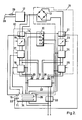
- La figure 2 illustre à l'aide d'un schéma bloc les principaux éléments d'un générateur de courant à utiliser dans un appareil suivant l'invention.
- La figure 3 montre une vue en coupe d'une bobine suivant l'invention.
- La figure 4 illustre les lignes de champ d'un champ magnétique engendré à l'aide d'un appareil suivant l'invention.
- La figure 5 illustre un premier type de noyau à utiliser dans une bobine suivant l'invention.
- La figure 6 illustre un deuxième type de noyau à utiliser dans une bobine suivant l'invention.
- La figure 7 illustre une bobine logée dans un boîtier attaché à une sangle.
- Figure 1 shows an overview of an example of a physiotherapy device according to the invention.
- FIG. 2 illustrates with the aid of a block diagram the main elements of a current generator to be used in an apparatus according to the invention.
- Figure 3 shows a sectional view of a coil according to the invention.
- FIG. 4 illustrates the field lines of a magnetic field generated using an apparatus according to the invention.
- FIG. 5 illustrates a first type of core to be used in a coil according to the invention.
- FIG. 6 illustrates a second type of core to be used in a coil according to the invention.
- Figure 7 illustrates a coil housed in a housing attached to a strap.
Dans le dessin, les mêmes éléments ou des éléments analogues portent une même référence.In the drawing, the same or similar elements have the same reference.
L'appareil de physiothérapie illustré à la figure 1 comporte un générateur 1 de courant électrique dont une sortie est reliée à l'aide d'un fil conducteur 2 à une bobine 3. La bobine est logée dans un boîtier 6, par exemple un boîtier en nylon ou en une autre matière plastique rigide et isolante. Le boîtier est de préférence pourvu de deux boucles 4 et 5 qui sont attachées à une sangle 50, tel qu'illustré à la figure 7, et qui permet alors de fixer le boîtier et la bobine autour d'une partie d'un corps à traiter. La sangle est de préférence pourvue de moyens adhésifs 51, 52 permettant de serrer la sangle autour de ladite partie du corps. De préférence les boucles 4 et 5 sont mobiles, permettant ainsi de faire tourner le boîtier autour de l'axe AB et donc de modifier le sens de la polarité du champ magnétique créé par la bobine lorsque cette dernière est alimentée en courant provenant du générateur 1.The physiotherapy appliance illustrated in FIG. 1 comprises an electric current generator 1, an output of which is connected by means of a conducting
Dans une autre forme de réalisation, l'appareil de physiothérapie suivant l'invention est agencé pour alimenter plusieurs bobines permettant ainsi d'appliquer un champ magnétique en plusieurs points du corps à traiter. De plus, en utilisant plusieurs bobines chacunes logées dans un boîtier et fixées à une ou plusieurs sangles tel qu'illustré à la figure 7, le fait qu'elles puissent tourner permet d'appliquer en un point un champ polarisé sud et en un autre point un champ polarisé nord.In another embodiment, the physiotherapy device according to the invention is arranged to supply several coils, thus making it possible to apply a magnetic field at several points of the body to be treated. In addition, by using several coils each housed in a box and fixed to one or more straps as illustrated in FIG. 7, the fact that they can rotate makes it possible to apply at one point a south polarized field and at another point a north polarized field.
Le générateur 1 de courant est agencé pour engendrer soit un courant continu, soit un courant alternatif, dont l'intensité est variable. Le générateur 1 est également pourvu de moyens pour faire varier la fréquence du courant. La sélection de ces différentes possibilités est réalisée à l'aide des commutateurs 7, 8 et 9 ainsi que d'un clavier de commande 10. Un tableau d'affichage 11, par exemple formé par un ensemble de LED's, permet l'affichage de la valeur du courant ainsi que d'autres informations comme par exemple la fréquence, la polarité, etc...The current generator 1 is arranged to generate either direct current or alternating current, the intensity of which is variable. The generator 1 is also provided with means for varying the frequency of the current. The selection of these different possibilities is carried out using switches 7, 8 and 9 as well as a
La figure 2 illustre à l'aide d'un schéma bloc les principaux éléments d'un générateur de courant faisant partie d'un appareil suivant l'invention. Le générateur comporte une entrée 28 à laquelle on applique une tension d'alimentation, par exemple 220 Volts en provenance d'un réseau. Cette tension est fournie à un transformateur 12 qui permet de transformer une tension primaire, par exemple de 220 Volts, en une ou plusieurs valeurs de tension secondaires, par exemple 9 Volts et/ou 12 Volts. Afin de limiter le courant fourni au générateur, un fusible 29, par exemple un fusible de 2 A, est monté dans une ligne d'arrivée du courant.FIG. 2 illustrates with the aid of a block diagram the main elements of a current generator forming part of an apparatus according to the invention. The generator has an
La sortie du transformateur 12 est reliée d'une part à un générateur 30 de courant alternatif et d'autre part à un générateur 31 de courant continu. Le générateur 30 de courant alternatif comporte un interrupteur 14, qui est par exemple commandé par une touche 10a du clavier de commande 10, et qui permet de brancher le générateur 30. L'interrupteur 14 est relié à un premier témoin lumineux 15, par exemple formé par un LED du tableau d'affichage 11, lequel premier témoin lumineux est allumé lorsque le générateur 30 est branché. Une sortie de l'interrupteur 14 est reliée à un régulateur de courant 16, par exemple une résistance variable. Le régulateur est positionnable (indiqué par la flèche) à l'aide d'un commutateur 7, permettant ainsi de faire varier l'intensité du courant débité. Une sortie du régulateur 16 est reliée à une entrée d'un sélecteur de fréquences 17 qui est commandé à l'aide du commutateur 8. Le sélecteur de fréquences permet de choisir la fréquence du courant alternatif fourni à la bobine et ainsi de choisir la fréquence du champ magnétique créé par la bobine 1. Le sélecteur 17 de fréquences est relié au tableau d'affichage 11, permettant ainsi d'afficher la fréquence choisie. De préférence la fréquence est variable en continu dans une plage de 1 à 100 Hz.The output of the
Une sortie du sélecteur 17 de fréquences est d'une part reliée à une première entrée 19 d'une unité de sélection 32 et d'autre part à une entrée d'un sélecteur d'alternances 18 dont une sortie est reliée à une deuxième entrée 20 de l'unité de sélection 32. Le sélecteur d'alternances 18 permet, lorsqu'il est branché, de sélectionner l'une ou l'autre alternance (demi-période) de l'onde de courant électrique et ainsi d'obtenir un champ magnétique pulsé nord ou sud, suivant que l'on ait choisi l'une ou l'autre demi-période. Le sélecteur d'alternances 18 est également relié au tableau d'affichage 11 permettant ainsi d'afficher laquelle des deux demi-périodes a été choisie. L'indication du choix d'une demi-période et le branchement de l'unité de sélection sont par exemple réalisés à l'aide d'une ou de deux touches (10b) du clavier de commande 10.An output of the frequency selector 17 is on the one hand connected to a
Le générateur de courant continu 31 comporte un pont de diodes 13, permettant de transformer le courant alternatif fourni à la sortie du transformateur 12 en un courant continu. Une sortie du pont de diodes 13 est reliée à un deuxième interrupteur 21, qui est par exemple également commandé par la touche 10a du clavier de commande 10, et qui permet de brancher le générateur de courant continu. La touche 10a du clavier de commande est agencée de telle sorte à empêcher que le générateur de courant continu et le générateur alternatif ne soient branchés en même temps, par exemple en utilisant un sélecteur pour la touche 10a. L'interrupteur 21 est relié à un LED 22 du tableau d'affichage qui, lorsqu'il est allumé, indique que le générateur de courant continu est branché.The direct
Une sortie de l'interrupteur 21 est reliée à un régulateur de courant 23, par exemple une résistance variable. Le régulateur 23 est positionnable à l'aide du commutateur 7 permettant ainsi de faire varier l'intensité du courant débité. Une sortie du régulateur 23 est reliée à un dispositif inverseur 24, qui permet de choisir la polarité du courant et donc du champ magnétique. Le dispositif inverseur 24 est relié à la touche 10c du clavier de commande qui permet ainsi de positionner le dispositif inverseur 24 et donc de modifier la polarité du courant. La touche 10c est également reliée au tableau d'affichage 11 pour permettre l'affichage, par exemple à l'aide d'un signe + ou -, de la polarité choisie. Une sortie du dispositif inverseur 24 est d'une part reliée à une troisième entrée 26 de l'unité de sélection 32 et d'autre part à une entrée d'un dispositif 25 d'interruption de courant. Une entrée de commande du dispositif 25 est reliée au commutateur 9. Le dispositif 25 d'interruption est muni de moyens, par exemple formés d'un circuit RC et d'un transistor, permettant d'interrompre le courant durant des périodes de temps dont la durée peut être variable, et d'obtenir ainsi une onde rectangulaire. La manipulation du commutateur 9 permet de faire varier la durée de ladite période de temps et donc la fréquence de l'onde rectangulaire. La fréquence peut ainsi par exemple varier entre 1 et 100 Hz. Une sortie du dispositif 25 est reliée à une quatrième entrée 27 de l'unité de sélection 32. La touche 10d du clavier est reliée à une autre entrée de commande du dispositif 25 et permet de brancher le dispositif 25. La touche 10d est également reliée au tableau d'affichage 11 permettant ainsi d'afficher que le dispositif 25 est branché.An output of the
L'unité de sélection 32 comporte une première respectivement une deuxième entrée de commande reliée à la touche du clavier de commande 10a qui commande l'interrupteur 14 respectivement à la touche 10b qui commande le sélectionneur d'alternances 18. Une troisième entrée de commande de l'unité de sélection 32 est reliée à la touche 10d qui commande le dispositif 25. En fonction du choix indiqué à l'aide du clavier 10, l'unité de sélection 32 choisit un signal présent sur l'une de ses quatres entrées 19, 20, 26 et 27 et le transmet à sa sortie, qui elle est reliée par l'intermédiaire d'un limitateur de courant 33 à la bobine (non reprise dans la figure 2).The
Lorsque à l'aide de la touche 10a le générateur de courant continu 31 respectivement le générateur de courant alternatif 30 a été choisi le LED 22 respectivement 15 sera allumé et l'unité de sélection 32 reliera l'une des entrées 26, 27 respectivement l'une des entrées 19, 20 avec sa sortie. Le choix entre les entrées 19, 20 respectivement les entrées 26, 27 est réalisé en fonction de la touche 10b respectivement 10c. Lorsque le sélecteur d'alternances 18 respectivement le dispositif 25 est branché, l'entrée 20 respectivement 27 sera reliée à la sortie.When using the button 10a the
La sortie du limitateur 33 de courant est également reliée au tableau d'affichage 11 permettant ainsi d'afficher sur un cadran 34 l'intensité du courant délivré à la bobine. Un cadran 35 permet d'afficher la fréquence du courant, telle que produite par le sélecteur de fréquences 17 ou le dispositif 25.The output of the
Le limitateur de courant sert, comme son nom l'indique, à limiter le courant (par exemple à maximum 200 mA) passant dans la bobine et permet ainsi de protéger la bobine.The current limiter serves, as its name suggests, to limit the current (for example to a maximum of 200 mA) passing through the coil and thus makes it possible to protect the coil.
Il va de soi que dans le cadre de l'invention diverses autres formes de réalisation pour le générateur 1 sont possibles. Ainsi dans une autre forme de réalisation le générateur 1 ne comporte pas d'unité de sélection 32 mais comporte par exemple quatre sorties individuelles auxquelles on peut chaque fois brancher la bobine. Dans ce dernier cas les touches 10a, b et d n'ont plus de raison d'être. Le générateur peut également comporter plusieurs sorties pour brancher plusieurs bobines.It goes without saying that in the context of the invention various other embodiments for the generator 1 are possible. Thus in another embodiment the generator 1 does not have a
Le courant électrique produit par le générateur 1 est fourni à la bobine 3 afin de créer un champ magnétique qui sera alors utilisé comme moyen thérapeutique. Cette utilisation à des fins thérapeutiques impose des normes particulières au champ magnétique engendré par la bobine, et donc à la bobine même. Ainsi les lignes de champ du champ magnétique doivent parfois être capables de pénétrer jusqu'à une distance de 40 cm dans le corps humain ou animal à traiter. De plus, les lignes de champ doivent, de préférence, être concentrées dans l'axe de la bobine et avoir une dispersion réduite. En effet, dans la magnéto-thérapie, il est important de pouvoir appliquer un champ magnétique à un point bien défini du corps qu'il faut traiter, et il faut parfois éviter que le champ magnétique soit appliqué sur des parties voisines du point qu'il faut traiter. En particulier pour des applications en accupunture cette restriction est primordiale. Il faut donc veiller à créer un champ magnétique d'une grande qualité ayant des lignes de champ d'une grande pureté. De plus, il faut aussi pour traiter certaines autres douleurs, telles par exemple des douleurs d'origine osseuse, par exemple une ostéomyélite, des champs magnétiques ayant une intensité magnétique d'au moins 7.500 Gauss. Par contre pour traiter d'autres types de douleurs plus superficielles, telles par exemple des douleurs de pathélogie tissulaire, il faut une intensité magnétique de 1.000 Gauss, ou il faut un champ pulsé comme par exemple pour traiter des douleurs inflammatoires ou des ulcères. L'intensité du champ magnétique requise pour combattre la lésion est essentiellement fonction de la profondeur à laquelle se trouve la lésion à traiter. Toutes ces différentes exigences imposent des normes très strictes à la construction de la bobine.The electric current produced by the generator 1 is supplied to the coil 3 in order to create a magnetic field which will then be used as a therapeutic means. This use for therapeutic purposes imposes particular standards on the magnetic field generated by the coil, and therefore on the coil itself. Thus the field lines of the magnetic field must sometimes be able to penetrate up to a distance of 40 cm into the human or animal body to be treated. In addition, the field lines should preferably be concentrated in the axis of the coil and have a reduced dispersion. Indeed, in magnetotherapy, it is important to be able to apply a magnetic field to a well-defined point on the body to be treated, and it is sometimes necessary to avoid the magnetic field being applied to parts close to the point that it must be treated. In particular for applications in accupunture this restriction is essential. Care must therefore be taken to create a high quality magnetic field having very pure field lines. In addition, it is also necessary to treat certain other pains, such as for example pains of bone origin, for example osteomyelitis, magnetic fields having a magnetic intensity of at least 7,500 Gauss. On the other hand, to treat other types of more superficial pain, such as tissue pathology pain, you need a magnetic intensity of 1,000 Gauss, or you need a pulsed field, for example to treat inflammatory pain or ulcers. The intensity of the magnetic field required to combat the lesion is essentially a function of the depth of the lesion to be treated. All these different requirements impose very strict standards on the construction of the coil.
Afin de pouvoir créer un champ magnétique capable de traiter efficacement un large éventail de douleurs, la bobine faisant partie d'un appareil de physiothérapie suivant l'invention satisfait à des normes bien particulières qui seront décrites en détail ci-dessous.In order to be able to create a magnetic field capable of effectively treating a wide range of pain, the coil forming part of a physiotherapy apparatus according to the invention meets very specific standards which will be described in detail below.
La figure 3 montre une vue en coupe d'une bobine 3 suivant l'invention. Le solénoïde 40 comporte au moins 1000 spires, mais de préférence 2000 spires d'un fil, en particulier un fil de cuivre ayant par exemple un diamètre de 0,25 mm. Afin d'augmenter la perméabilité magnétique relative (µR) de la bobine et donc l'intensité magnétique et le flux magnétique du champ magnétique engendré, la bobine comporte un noyau 41 fixé à l'intérieur du solénoïde. De préférence la bobine comporte une coupe circulaire.Figure 3 shows a sectional view of a coil 3 according to the invention. The
Pour obtenir le champ magnétique répondant aux normes voulues, il est important que la bobine ait une longueur d'au moins deux fois celle du diamètre du noyau. De préférence la longueur de la bobine est à peu près quatre fois celle du diamètre du noyau. Par exemple lorsque le noyau formé par un cylindre, comporte un diamètre de 10 mm il comporte une longueur de 38 mm qui correspond également à celle de la bobine, puisque de préférence le noyau s'étend sur toute la longueur de la bobine. Ce choix de dimension de la bobine permet en effet de concentrer les lignes de champ du champ magnétique dans l'axe du noyau et donc d'engendrer un champ magnétique ayant une homogénéité considérable.To obtain the magnetic field that meets the required standards, it is important that the coil has a length of at least twice that of the diameter of the core. Preferably the length of the coil is about four times that of the diameter of the core. For example when the core formed by a cylinder has a diameter of 10 mm it has a length of 38 mm which also corresponds to that of the coil, since preferably the core extends over the entire length of the coil. This choice of size of the coil in fact makes it possible to concentrate the field lines of the magnetic field in the axis of the core and therefore to generate a magnetic field having considerable homogeneity.
L'homogénéité du champ magnétique est encore améliorée en utilisant pour le noyau en acier dont la teneur en carbone est inférieure ou égale à 0,40 %, mais de préférence inférieure ou égale à 0,25 %. L'emploi d'un tel acier permet une plus forte concentration des lignes de champ qui de ce fait se trouvent rapidement en état de saturation dans le noyau. Ce phénomène fait apparaître un spectre de lignes de champ très dense pouvant atteindre un point situé à peu près 40 cm du centre de la bobine.The homogeneity of the magnetic field is further improved by using for the steel core whose carbon content is less than or equal to 0.40%, but preferably less than or equal to 0.25%. The use of such a steel allows a higher concentration of the field lines which therefore quickly find themselves in a state of saturation in the core. This phenomenon reveals a spectrum of very dense field lines that can reach a point located approximately 40 cm from the center of the coil.
Pour obtenir un tel noyau il est nécessaire de faire subir un traitement à l'acier. Ce traitement consiste à faire subir au noyau un rapide revenu à une température de maximum 600°C, suivi d'un écrouissage très léger pendant la période de refroidissement du noyau. Durant l'opération écrouissage l'acier du noyau est soumis à un martelage permettant d'assouplir l'acier et ainsi de réduire pratiquement à zéro des courants de Foucault qui pourraient être induits dans le noyau, lorsqu'un courant électrique passe à travers le solénoïde. On obtient ainsi très peu de pertes de courants dans la bobine qui de ce fait ne chauffera que très peu durant l'emploi. De cette façon on évite également les pertes d'énergie et par conséquent cela permet de maintenir plus longtemps le champ magnétique.To obtain such a core it is necessary to subject the steel to a treatment. This treatment consists in subjecting the core to rapid tempering at a temperature of maximum 600 ° C., followed by very light work hardening during the cooling period of the nucleus. During the work hardening operation the steel of the core is subjected to a hammering allowing to soften the steel and thus to reduce practically to zero eddy currents which could be induced in the core, when an electric current passes through the solenoid. There is thus very little loss of current in the coil which therefore will heat very little during use. In this way, energy losses are also avoided and consequently this makes it possible to maintain the magnetic field longer.
Comme matériau formant le noyau il est également possible d'utiliser du fer étiré à froid (par exemple de l'acier calibré ST37), ou du fer poli. Le choix des matériaux du noyau est dicté par le fait que de préférence la perméabilité magnétique relative est inférieure à 1.200. En effet pour limiter la dispersion des lignes de champ et l'énergie transmise (une trop forte énergie pourrait causer des dégâts au corps à traiter) il est important que le champ magnétique ne dépasse pas une intensité de par exemple 10.000 Gauss à l'intérieur du corps à traiter.As the material forming the core it is also possible to use cold drawn iron (for example ST37 calibrated steel), or polished iron. The choice of core materials is dictated by the fact that preferably the relative magnetic permeability is less than 1,200. Indeed to limit the dispersion of the field lines and the transmitted energy (too strong energy could cause damage to the body to be treated) it is important that the magnetic field does not exceed an intensity of for example 10,000 Gauss inside of the body to be treated.
La figure 4 illustre les lignes de champ d'un champ magnétique engendré à l'aide d'un appareil suivant l'invention. Comme on peut le voir sur cette figure 4, les lignes de champ sont concentrées dans l'axe XX′ du noyau et n'ont que très peu de dispersion permettant ainsi de focaliser le champ magnétique sur un endroit bien déterminé du corps à traiter.FIG. 4 illustrates the field lines of a magnetic field generated using an apparatus according to the invention. As can be seen in this FIG. 4, the field lines are concentrated in the axis XX ′ of the nucleus and have only very little dispersion, thus making it possible to focus the magnetic field on a well-defined location on the body to be treated.
La figure 5 illustre une autre forme de réalisation d'un noyau à utiliser dans une bobine suivant l'invention. Le noyau a son centre 42 fait d'une autre qualité d'acier que celle utilisée pour faire la paroi du noyau. Par exemple la paroi est réalisée en un acier plus dur que celui utilisé pour le centre du noyau. La paroi est par exemple réalisée en acier poli alors que le centre est en acier étiré à froid. On obtient ainsi que la perméabilité magnétique relative dans une zone située autour de l'axe central du noyau est supérieure à celle de la zone située autour de la paroi du noyau.FIG. 5 illustrates another embodiment of a core to be used in a coil according to the invention. The core has its
La figure 6 illustre encore une autre forme de réalisation d'un noyau à utiliser dans une bobine suivant l'invention. Le noyau est constitué d'un assemblage de baguettes de soudage en acier cuivré, par exemple du type G-y 41 (Norme ISO 636/G233). Les ba guettes sont assemblées de telle sorte à former un cylindre ayant par exemple un diamètre de 10 mm et une longueur de 38 mm.FIG. 6 illustrates yet another embodiment of a core to be used in a coil according to the invention. The core consists of an assembly of copper rod welding rods, for example of the
Le tableau ci-dessous donne, à titre d'exemple, quelques valeurs du champ magnétique engendré par l'appareil suivant l'invention. Les valeurs sont obtenues en utilisant une bobine de 38 mm de longueur avec 2000 spires et un noyau de 10 mm de diamètre fabriqué en acier doux et ayant une perméabilité magnétique relative de par exemple 500.
Grâce au diverses possibilités du générateur 1, il est possible de créer à l'aide de la bobine divers types de champs magnétiques. Ainsi en optant pour un courant continu (touche 10a) on peut créer un champ magnétique statique dont l'intensité peut par exemple varier (commutateur 7) entre 0 et 10.000 Gauss. Les champs magnétiques statiques sont utilisés lorsque le thérapeute souhaite obtenir une action antalgique ou un effet rééquilibrant du système nerveux autonome. La touche 10c permet d'inverser la polarité du courant et donc celle du champ magnétique sans pour autant devoir inverser l'orientation de la bobine. En effet lorsque le pôle nord est en contact avec le corps à traiter on obtient un effet de décontraction qui diminue le tonus musculaire, qui est vaso-dilatateur et cholinergique à prédominance anti-stress. Par contre lorsque le pôle sud est en contact avec le corps à traiter on obtient un effet de contraction qui augmente le tonus musculaire. Les champs magnétiques venant vers le pôle sud de la bobine provoquent des phénomènes de vaso- constriction qui s'opposent aux processus vaso-dilatatoires de l'inflammation.Thanks to the various possibilities of generator 1, it is possible to create various types of magnetic fields using the coil. Thus by opting for a direct current (key 10a) one can create a static magnetic field whose intensity can for example vary (switch 7) between 0 and 10,000 Gauss. Static magnetic fields are used when the therapist wishes to obtain an analgesic action or a rebalancing effect of the autonomic nervous system. The key 10c makes it possible to reverse the polarity of the current and therefore that of the magnetic field without having to reverse the orientation of the coil. When the north pole is in contact with the body to be treated, a relaxation effect is obtained which reduces muscle tone, which is vasodilator and cholinergic, predominantly anti-stress. On the other hand, when the south pole is in contact with the body to be treated, a contraction effect is obtained which increases the muscle tone. Magnetic fields coming towards the south pole of the coil cause vaso- constriction that oppose the vasodilatory processes of inflammation.
Le dispositif d'interruption 25 permet d'obtenir un champ magnétique pulsé nord ou sud suivant la polarité indiquée par la touche 10c.The
On peut également obtenir un champ magnétique pulsé à partir du générateur de courant 30 alternatif. Quelques exemples de traitement thérapeutique à l'aide de champs magnétiques pulsés sont donnés ci-dessous.
Enfin en branchant (touche 10b) le sélecteur d'alternance 18 on obtient un champ magnétique pulsé nord ou sud en fonction du choix de l'opérateur.Finally by plugging in (key 10b) the
Claims (17)
Applications Claiming Priority (2)
| Application Number | Priority Date | Filing Date | Title |
|---|---|---|---|
| BE8801372 | 1988-12-06 | ||
| BE8801372A BE1002610A6 (en) | 1988-12-06 | 1988-12-06 | PHYSIOTHERAPY APPARATUS FOR PRODUCING A MAGNETIC FIELD FOR USE AS A THERAPEUTIC MEANS. |
Publications (2)
| Publication Number | Publication Date |
|---|---|
| EP0373141A2 true EP0373141A2 (en) | 1990-06-13 |
| EP0373141A3 EP0373141A3 (en) | 1991-03-13 |
Family
ID=3883760
Family Applications (1)
| Application Number | Title | Priority Date | Filing Date |
|---|---|---|---|
| EP19890870199 Withdrawn EP0373141A3 (en) | 1988-12-06 | 1989-12-05 | Physiotherapeutic apparatus to create a magnetic field used as a therapeutic means |
Country Status (7)
| Country | Link |
|---|---|
| US (1) | US5085626A (en) |
| EP (1) | EP0373141A3 (en) |
| BE (1) | BE1002610A6 (en) |
| CA (1) | CA2004547A1 (en) |
| DK (1) | DK603989A (en) |
| FI (1) | FI895825A0 (en) |
| NO (1) | NO894780L (en) |
Cited By (4)
| Publication number | Priority date | Publication date | Assignee | Title |
|---|---|---|---|---|
| ES2048678A2 (en) * | 1992-10-06 | 1994-03-16 | Suros Frigola | System for treating illnesses using bio-resonance therapies. |
| FR2888983A1 (en) * | 2005-07-19 | 2007-01-26 | Philippe Charles Marc Beaucamp | Constant/variable magnetic field producing device for placing user in magnetic field during his sleep, has case supplying coil with low voltage by intermediary of power regulator, where coil is fixed on inner periphery of mattress support |
| EP2138204A1 (en) * | 2008-06-25 | 2009-12-30 | Medisana AG | Device for treating in particular arthrosis, at least when using pulsing magnetic fields |
| WO2013041862A1 (en) * | 2011-09-20 | 2013-03-28 | Isis Innovation Ltd | Magnetic dental stimulator |
Families Citing this family (52)
| Publication number | Priority date | Publication date | Assignee | Title |
|---|---|---|---|---|
| US6322491B1 (en) | 1992-01-21 | 2001-11-27 | Nu-Magnetics, Inc. | Flexible magnetic insole |
| AU661789B2 (en) * | 1992-08-26 | 1995-08-03 | Larkace Pty Ltd | Magnetic field induction multi-pulse therapy |
| GB2270000B (en) * | 1992-08-26 | 1996-04-24 | Robert John Grace | Magnetic field induction multi-pulse therapy |
| US5562706A (en) * | 1995-01-11 | 1996-10-08 | Electro Anti Age, Inc. | Device for cosmetic and relaxation treatment |
| US5720046A (en) * | 1995-06-29 | 1998-02-24 | Lopez; Richard A. | Articles of humanwear merchandise having magnetic structure for producing magnetic healing effects |
| GB9523513D0 (en) * | 1995-11-17 | 1996-01-17 | Ecoflow Ltd | Magnotherapy device |
| GB2325624B (en) * | 1997-05-28 | 2001-02-07 | David Jehan | Strap for trans-dermal therapy |
| US6083149A (en) * | 1997-10-22 | 2000-07-04 | Emf Therapeutics, Inc. | Magnetic field device and method for inhibiting angiogenesis and retarding growth rates of tumors in mammals |
| US6149577A (en) * | 1999-03-18 | 2000-11-21 | Emf Therapeutics, Inc. | Apparatus and method for creating a substantially contained, finite magnetic field useful for relieving the symptoms pain and discomfort associated with degenerative diseases and disorders in mammals |
| US6332862B1 (en) | 1999-12-21 | 2001-12-25 | Michael Zandman | Articles of clothing incorporating magnets for therapeutic purposes |
| US6275996B1 (en) | 2000-01-28 | 2001-08-21 | Acushnet Company | Articles with removable elements |
| EP1333886A2 (en) * | 2000-10-24 | 2003-08-13 | Philip John Manison | Physiological effect device |
| DE10302439A1 (en) * | 2003-01-21 | 2004-07-29 | Günther, Andreas | Magnetic field applicator for treatment of patients using magnetic field therapy, where one end of the applicator has a blanking element to increase the field concentration at the operating end |
| US8262556B2 (en) * | 2005-12-19 | 2012-09-11 | Neuralieve, Inc. | Magnetic pulsing system for inducing electric currents in a human body |
| US20080097142A1 (en) * | 2006-10-20 | 2008-04-24 | Paul Savage | Magnetic field generator, method of generating a pulsed sinusoidal magnetic wave and magnetic field generator system |
| TWM315580U (en) * | 2007-01-23 | 2007-07-21 | Shin-Shiang Pan | Electro-magnetic field therapeutic device |
| US20090012348A1 (en) * | 2007-07-07 | 2009-01-08 | Doyle Dean Simpson | Magnetotherapy |
| DE102012013534B3 (en) | 2012-07-05 | 2013-09-19 | Tobias Sokolowski | Apparatus for repetitive nerve stimulation for the degradation of adipose tissue by means of inductive magnetic fields |
| JP2016187364A (en) * | 2013-09-20 | 2016-11-04 | 第一高周波工業株式会社 | Magnetic flux irradiation device |
| US9919161B2 (en) | 2015-07-01 | 2018-03-20 | Btl Holdings Limited | Method of neural structure stimulation by magnetic field |
| US11491342B2 (en) | 2015-07-01 | 2022-11-08 | Btl Medical Solutions A.S. | Magnetic stimulation methods and devices for therapeutic treatments |
| US10124187B2 (en) | 2015-04-28 | 2018-11-13 | Btl Holdings Limited | Combination of radiofrequency and magnetic treatment methods |
| US9636519B2 (en) | 2015-07-01 | 2017-05-02 | Btl Holdings Limited | Magnetic stimulation methods and devices for therapeutic treatments |
| US10709894B2 (en) | 2015-07-01 | 2020-07-14 | Btl Medical Technologies S.R.O. | Aesthetic method of biological structure treatment by magnetic field |
| US10549109B2 (en) | 2015-07-01 | 2020-02-04 | Btl Medical Technologies S.R.O. | Aesthetic method of biological structure treatment by magnetic field |
| US10549110B1 (en) | 2015-07-01 | 2020-02-04 | Btl Medical Technologies S.R.O. | Aesthetic method of biological structure treatment by magnetic field |
| US10695575B1 (en) | 2016-05-10 | 2020-06-30 | Btl Medical Technologies S.R.O. | Aesthetic method of biological structure treatment by magnetic field |
| US11266850B2 (en) | 2015-07-01 | 2022-03-08 | Btl Healthcare Technologies A.S. | High power time varying magnetic field therapy |
| US10471269B1 (en) | 2015-07-01 | 2019-11-12 | Btl Medical Technologies S.R.O. | Aesthetic method of biological structure treatment by magnetic field |
| US10493293B2 (en) | 2015-07-01 | 2019-12-03 | Btl Medical Technologies S.R.O. | Aesthetic method of biological structure treatment by magnetic field |
| US9937358B2 (en) | 2015-07-01 | 2018-04-10 | Btl Holdings Limited | Aesthetic methods of biological structure treatment by magnetic field |
| US9974519B1 (en) | 2015-07-01 | 2018-05-22 | Btl Holdings Limited | Aesthetic method of biologoical structure treatment by magnetic field |
| US10478634B2 (en) | 2015-07-01 | 2019-11-19 | Btl Medical Technologies S.R.O. | Aesthetic method of biological structure treatment by magnetic field |
| US10821295B1 (en) | 2015-07-01 | 2020-11-03 | Btl Medical Technologies S.R.O. | Aesthetic method of biological structure treatment by magnetic field |
| US10695576B2 (en) | 2015-07-01 | 2020-06-30 | Btl Medical Technologies S.R.O. | Aesthetic method of biological structure treatment by magnetic field |
| US20180001107A1 (en) | 2016-07-01 | 2018-01-04 | Btl Holdings Limited | Aesthetic method of biological structure treatment by magnetic field |
| US10569094B2 (en) | 2015-07-01 | 2020-02-25 | Btl Medical Technologies S.R.O. | Aesthetic method of biological structure treatment by magnetic field |
| US10245439B1 (en) | 2015-07-01 | 2019-04-02 | Medical Technologies Cz A.S. | Aesthetic method of biological structure treatment by magnetic field |
| US10478633B2 (en) | 2015-07-01 | 2019-11-19 | Btl Medical Technologies S.R.O. | Aesthetic method of biological structure treatment by magnetic field |
| US11253717B2 (en) | 2015-10-29 | 2022-02-22 | Btl Healthcare Technologies A.S. | Aesthetic method of biological structure treatment by magnetic field |
| US11247039B2 (en) | 2016-05-03 | 2022-02-15 | Btl Healthcare Technologies A.S. | Device including RF source of energy and vacuum system |
| US11464993B2 (en) | 2016-05-03 | 2022-10-11 | Btl Healthcare Technologies A.S. | Device including RF source of energy and vacuum system |
| US11534619B2 (en) | 2016-05-10 | 2022-12-27 | Btl Medical Solutions A.S. | Aesthetic method of biological structure treatment by magnetic field |
| US10583287B2 (en) | 2016-05-23 | 2020-03-10 | Btl Medical Technologies S.R.O. | Systems and methods for tissue treatment |
| US10556122B1 (en) | 2016-07-01 | 2020-02-11 | Btl Medical Technologies S.R.O. | Aesthetic method of biological structure treatment by magnetic field |
| US11896823B2 (en) | 2017-04-04 | 2024-02-13 | Btl Healthcare Technologies A.S. | Method and device for pelvic floor tissue treatment |
| US10039929B1 (en) | 2017-04-04 | 2018-08-07 | BLT Holdings Limited | Method and device for pelvic floor tissue treatment |
| US20190232075A1 (en) * | 2018-01-30 | 2019-08-01 | Kenko Patto, Llc. | Electromagnetic device for therapies |
| EP4292645A3 (en) | 2019-04-11 | 2024-01-31 | BTL Medical Solutions a.s. | Devices for aesthetic treatment of biological structures by radiofrequency and magnetic energy |
| BR112022022112A2 (en) | 2020-05-04 | 2022-12-13 | Btl Healthcare Tech A S | DEVICE FOR UNASSISTED PATIENT TREATMENT |
| US11878167B2 (en) | 2020-05-04 | 2024-01-23 | Btl Healthcare Technologies A.S. | Device and method for unattended treatment of a patient |
| US11896816B2 (en) | 2021-11-03 | 2024-02-13 | Btl Healthcare Technologies A.S. | Device and method for unattended treatment of a patient |
Citations (6)
| Publication number | Priority date | Publication date | Assignee | Title |
|---|---|---|---|---|
| DE397227C (en) * | 1924-06-30 | August Sonderegger | Electromagnetic healing apparatus | |
| US2897411A (en) * | 1956-08-17 | 1959-07-28 | Gordon Brown Company | Electromagnet and control circuit |
| GB1058319A (en) * | 1964-08-18 | 1967-02-08 | Ulf Tore Walden | Improvements in or relating to therapeutic apparatus |
| DE1956305A1 (en) * | 1969-11-08 | 1971-05-19 | Brown Ivan H | Electromagnet with a tubular housing |
| DE3152008C1 (en) * | 1981-12-31 | 1983-07-07 | Fried. Krupp Gmbh, 4300 Essen | Elongated magnetic switching core |
| EP0193079A2 (en) * | 1985-02-27 | 1986-09-03 | Hitachi, Ltd. | Method of manufacturing electromagnetic members |
Family Cites Families (9)
| Publication number | Priority date | Publication date | Assignee | Title |
|---|---|---|---|---|
| US765690A (en) * | 1902-09-12 | 1904-07-26 | Reinhold Trueb | Apparatus for producing gyratory magnetic lines of force for therapeutic purposes. |
| US1216183A (en) * | 1916-09-18 | 1917-02-13 | Charles M Swingle | Electrotherapeutic rejuvenator. |
| US3337776A (en) * | 1964-06-10 | 1967-08-22 | Guidoni | Biomedical apparatus for generating controllable magnetic fields |
| US3963959A (en) * | 1974-09-26 | 1976-06-15 | General Electric Company | Ground fault circuit interrupting device and differential current sensor therefor |
| US4327344A (en) * | 1980-03-31 | 1982-04-27 | Hi-G Incorporated | Solenoid with mechanically latchable plunger |
| US4356476A (en) * | 1980-09-15 | 1982-10-26 | W. E. Healey & Associates, Inc. | Multiple alarm detector monitoring and command system |
| US4911686A (en) * | 1983-06-29 | 1990-03-27 | Sheldon Thaler | Apparatus for reactively applying electrical energy pulses to a living body |
| US4674482A (en) * | 1984-09-12 | 1987-06-23 | Irt, Inc. | Pulse electro-magnetic field therapy device with auto bias circuit |
| US4850959A (en) * | 1988-08-02 | 1989-07-25 | Bioresearch, Inc. | Bioelectrochemical modulation of biological functions using resonant/non-resonant fields synergistically |
-
1988
- 1988-12-06 BE BE8801372A patent/BE1002610A6/en not_active IP Right Cessation
-
1989
- 1989-11-30 DK DK603989A patent/DK603989A/en not_active Application Discontinuation
- 1989-11-30 NO NO89894780A patent/NO894780L/en unknown
- 1989-12-04 CA CA002004547A patent/CA2004547A1/en not_active Abandoned
- 1989-12-05 EP EP19890870199 patent/EP0373141A3/en not_active Withdrawn
- 1989-12-05 FI FI895825A patent/FI895825A0/en not_active IP Right Cessation
- 1989-12-05 US US07/446,334 patent/US5085626A/en not_active Expired - Fee Related
Patent Citations (6)
| Publication number | Priority date | Publication date | Assignee | Title |
|---|---|---|---|---|
| DE397227C (en) * | 1924-06-30 | August Sonderegger | Electromagnetic healing apparatus | |
| US2897411A (en) * | 1956-08-17 | 1959-07-28 | Gordon Brown Company | Electromagnet and control circuit |
| GB1058319A (en) * | 1964-08-18 | 1967-02-08 | Ulf Tore Walden | Improvements in or relating to therapeutic apparatus |
| DE1956305A1 (en) * | 1969-11-08 | 1971-05-19 | Brown Ivan H | Electromagnet with a tubular housing |
| DE3152008C1 (en) * | 1981-12-31 | 1983-07-07 | Fried. Krupp Gmbh, 4300 Essen | Elongated magnetic switching core |
| EP0193079A2 (en) * | 1985-02-27 | 1986-09-03 | Hitachi, Ltd. | Method of manufacturing electromagnetic members |
Cited By (4)
| Publication number | Priority date | Publication date | Assignee | Title |
|---|---|---|---|---|
| ES2048678A2 (en) * | 1992-10-06 | 1994-03-16 | Suros Frigola | System for treating illnesses using bio-resonance therapies. |
| FR2888983A1 (en) * | 2005-07-19 | 2007-01-26 | Philippe Charles Marc Beaucamp | Constant/variable magnetic field producing device for placing user in magnetic field during his sleep, has case supplying coil with low voltage by intermediary of power regulator, where coil is fixed on inner periphery of mattress support |
| EP2138204A1 (en) * | 2008-06-25 | 2009-12-30 | Medisana AG | Device for treating in particular arthrosis, at least when using pulsing magnetic fields |
| WO2013041862A1 (en) * | 2011-09-20 | 2013-03-28 | Isis Innovation Ltd | Magnetic dental stimulator |
Also Published As
| Publication number | Publication date |
|---|---|
| CA2004547A1 (en) | 1990-06-06 |
| EP0373141A3 (en) | 1991-03-13 |
| DK603989A (en) | 1990-06-07 |
| BE1002610A6 (en) | 1991-04-09 |
| DK603989D0 (en) | 1989-11-30 |
| NO894780D0 (en) | 1989-11-30 |
| FI895825A0 (en) | 1989-12-05 |
| NO894780L (en) | 1990-06-07 |
| US5085626A (en) | 1992-02-04 |
Similar Documents
| Publication | Publication Date | Title |
|---|---|---|
| EP0373141A2 (en) | Physiotherapeutic apparatus to create a magnetic field used as a therapeutic means | |
| EP0205384B1 (en) | Hyperthermia treatment device | |
| EP0988085B1 (en) | Device for electromagnetic cutaneous stimulation for treating pathological conditions | |
| CA1115833A (en) | High frequency electromagnetic wave transmitters | |
| FR2634383A1 (en) | ION BEAM IRRADIATION APPARATUS | |
| WO1992000119A1 (en) | Method and device for treating epilepsy | |
| KR100484618B1 (en) | Apparatus for stimulating nerves | |
| EP0888704B1 (en) | Induction heating device for surface treating the teeth of a mechanical part | |
| JPH1057441A (en) | Combined beauty processor | |
| EP0005663B1 (en) | Apparatus for the treatment of a living substrate | |
| JPS6354393B2 (en) | ||
| EP0511059B1 (en) | Method and apparatus for controlling the transverse magnetic field in an undulator for the generation of light from an electron beam | |
| FR2749515A1 (en) | Isolation tank for personal use with various relaxation means | |
| EP1352615B1 (en) | Flashlight treatment device | |
| EP0024070A1 (en) | Process and apparatus for the magnetic treatment of living organisms | |
| FR2702663A1 (en) | Proton therapy installation | |
| CA3097257C (en) | Device for generating a very-low-frequency pulsed magnetic field carried by a very-low-frequency alternating magnetic field | |
| FR2470452A1 (en) | Electromagnetic transmission regulator for therapeutical use - has electromagnetic wave transmitter and wave form transmitter electrically connected to each other and to HF generator | |
| FR2583974A1 (en) | Device for monitoring exteroceptive sensitivities in particular for medical and in particular neurological applications | |
| FR2704761B1 (en) | CURRENT GENERATING APPARATUS FOR THERAPEUTIC TREATMENTS IN THE FIELD OF BIOPHYSICS AND PHYSIOLOGY. | |
| FR2585579A1 (en) | Electromagnetic cushion for treating skin disorders | |
| FR2468380A2 (en) | Magnetic flux source for medical and biological use - has permanent magnet or electromagnet and polarising screen with flux transfer by flexible fibre bundle | |
| FR2948226A1 (en) | DEVICE CREATING A VARIABLE MAGNETIC FIELD VARIABLE AT FREQUENCY EQUIVALENT TO THE RHYTHM DELTA, THEN CONSTANT SO THAT THE USER DORMS AS PLACE ON THE NORTH OR SOUTH MAGNETIC POLE | |
| WO2003063965A1 (en) | Method and device for curing different diseases by physiotherapeutic action | |
| FR2616967A1 (en) | SWITCH USING SUPERCONDUCTIVITY AND ANTENNA APPLICATION FOR NUCLEAR MAGNETIC RESONANCE IMAGING APPARATUS |
Legal Events
| Date | Code | Title | Description |
|---|---|---|---|
| PUAI | Public reference made under article 153(3) epc to a published international application that has entered the european phase |
Free format text: ORIGINAL CODE: 0009012 |
|
| AK | Designated contracting states |
Kind code of ref document: A2 Designated state(s): AT BE CH DE ES FR GB GR IT LI SE |
|
| PUAL | Search report despatched |
Free format text: ORIGINAL CODE: 0009013 |
|
| AK | Designated contracting states |
Kind code of ref document: A3 Designated state(s): AT BE CH DE ES FR GB GR IT LI SE |
|
| 17P | Request for examination filed |
Effective date: 19910528 |
|
| STAA | Information on the status of an ep patent application or granted ep patent |
Free format text: STATUS: THE APPLICATION IS DEEMED TO BE WITHDRAWN |
|
| 18D | Application deemed to be withdrawn |
Effective date: 19920701 |