EP0372907B1 - Breitbandige Superfluoreszenz-Faserlaserquelle - Google Patents
Breitbandige Superfluoreszenz-Faserlaserquelle Download PDFInfo
- Publication number
- EP0372907B1 EP0372907B1 EP89312666A EP89312666A EP0372907B1 EP 0372907 B1 EP0372907 B1 EP 0372907B1 EP 89312666 A EP89312666 A EP 89312666A EP 89312666 A EP89312666 A EP 89312666A EP 0372907 B1 EP0372907 B1 EP 0372907B1
- Authority
- EP
- European Patent Office
- Prior art keywords
- fiber
- light
- spectrum
- coupler
- wavelengths
- Prior art date
- Legal status (The legal status is an assumption and is not a legal conclusion. Google has not performed a legal analysis and makes no representation as to the accuracy of the status listed.)
- Expired - Lifetime
Links
- 239000000835 fiber Substances 0.000 title claims description 305
- 238000010168 coupling process Methods 0.000 claims description 94
- 230000008878 coupling Effects 0.000 claims description 86
- 238000005859 coupling reaction Methods 0.000 claims description 86
- 238000001228 spectrum Methods 0.000 claims description 64
- 238000005086 pumping Methods 0.000 claims description 63
- 239000013307 optical fiber Substances 0.000 claims description 59
- 230000003287 optical effect Effects 0.000 claims description 57
- 239000000463 material Substances 0.000 claims description 43
- 238000005286 illumination Methods 0.000 claims description 21
- 230000002123 temporal effect Effects 0.000 claims description 19
- 238000000295 emission spectrum Methods 0.000 claims description 14
- 230000001419 dependent effect Effects 0.000 claims description 13
- 238000001914 filtration Methods 0.000 claims description 11
- 238000000034 method Methods 0.000 claims description 11
- 229910052779 Neodymium Inorganic materials 0.000 claims description 10
- -1 rare earth ion Chemical class 0.000 claims description 9
- QEFYFXOXNSNQGX-UHFFFAOYSA-N neodymium atom Chemical compound [Nd] QEFYFXOXNSNQGX-UHFFFAOYSA-N 0.000 claims description 7
- 239000000146 host glass Substances 0.000 claims description 6
- 150000004760 silicates Chemical class 0.000 claims description 6
- 229910052761 rare earth metal Inorganic materials 0.000 claims description 5
- 229910052691 Erbium Inorganic materials 0.000 claims description 4
- UYAHIZSMUZPPFV-UHFFFAOYSA-N erbium Chemical compound [Er] UYAHIZSMUZPPFV-UHFFFAOYSA-N 0.000 claims description 4
- 230000001939 inductive effect Effects 0.000 claims description 4
- 229910019142 PO4 Inorganic materials 0.000 claims description 3
- 229910052769 Ytterbium Inorganic materials 0.000 claims description 3
- 239000003513 alkali Substances 0.000 claims description 3
- 239000005385 borate glass Substances 0.000 claims description 3
- 235000021317 phosphate Nutrition 0.000 claims description 3
- 150000003013 phosphoric acid derivatives Chemical class 0.000 claims description 3
- 150000002910 rare earth metals Chemical class 0.000 claims description 3
- NAWDYIZEMPQZHO-UHFFFAOYSA-N ytterbium Chemical compound [Yb] NAWDYIZEMPQZHO-UHFFFAOYSA-N 0.000 claims description 3
- 230000006870 function Effects 0.000 description 49
- VYPSYNLAJGMNEJ-UHFFFAOYSA-N Silicium dioxide Chemical compound O=[Si]=O VYPSYNLAJGMNEJ-UHFFFAOYSA-N 0.000 description 26
- 230000003993 interaction Effects 0.000 description 23
- 230000000694 effects Effects 0.000 description 20
- 238000010586 diagram Methods 0.000 description 19
- 230000006872 improvement Effects 0.000 description 16
- 239000013078 crystal Substances 0.000 description 15
- 230000008901 benefit Effects 0.000 description 14
- 230000002269 spontaneous effect Effects 0.000 description 14
- 238000004364 calculation method Methods 0.000 description 13
- 239000000377 silicon dioxide Substances 0.000 description 13
- 238000005253 cladding Methods 0.000 description 11
- 230000003321 amplification Effects 0.000 description 10
- 230000005540 biological transmission Effects 0.000 description 10
- 230000001965 increasing effect Effects 0.000 description 10
- 238000003199 nucleic acid amplification method Methods 0.000 description 10
- 230000008859 change Effects 0.000 description 9
- 150000002500 ions Chemical class 0.000 description 8
- 238000010521 absorption reaction Methods 0.000 description 6
- 238000000862 absorption spectrum Methods 0.000 description 6
- 230000005855 radiation Effects 0.000 description 6
- 238000012546 transfer Methods 0.000 description 6
- 230000007423 decrease Effects 0.000 description 5
- 239000003365 glass fiber Substances 0.000 description 5
- 230000005283 ground state Effects 0.000 description 5
- 230000001808 coupling effect Effects 0.000 description 4
- 239000000382 optic material Substances 0.000 description 4
- 239000011149 active material Substances 0.000 description 3
- 239000002585 base Substances 0.000 description 3
- 238000006243 chemical reaction Methods 0.000 description 3
- 239000011521 glass Substances 0.000 description 3
- 230000001902 propagating effect Effects 0.000 description 3
- 238000000926 separation method Methods 0.000 description 3
- 238000004458 analytical method Methods 0.000 description 2
- 229910052681 coesite Inorganic materials 0.000 description 2
- 230000001427 coherent effect Effects 0.000 description 2
- 229910052906 cristobalite Inorganic materials 0.000 description 2
- 230000003247 decreasing effect Effects 0.000 description 2
- 238000009826 distribution Methods 0.000 description 2
- 239000000975 dye Substances 0.000 description 2
- 238000005516 engineering process Methods 0.000 description 2
- 238000012986 modification Methods 0.000 description 2
- 230000004048 modification Effects 0.000 description 2
- 239000003921 oil Substances 0.000 description 2
- 230000010355 oscillation Effects 0.000 description 2
- 230000003071 parasitic effect Effects 0.000 description 2
- 238000002310 reflectometry Methods 0.000 description 2
- 239000004065 semiconductor Substances 0.000 description 2
- 229910052682 stishovite Inorganic materials 0.000 description 2
- 125000005504 styryl group Chemical group 0.000 description 2
- 230000007704 transition Effects 0.000 description 2
- 229910052905 tridymite Inorganic materials 0.000 description 2
- 230000005374 Kerr effect Effects 0.000 description 1
- XUIMIQQOPSSXEZ-UHFFFAOYSA-N Silicon Chemical compound [Si] XUIMIQQOPSSXEZ-UHFFFAOYSA-N 0.000 description 1
- 230000009471 action Effects 0.000 description 1
- 239000000654 additive Substances 0.000 description 1
- 230000000996 additive effect Effects 0.000 description 1
- 230000003466 anti-cipated effect Effects 0.000 description 1
- 230000002301 combined effect Effects 0.000 description 1
- 238000013461 design Methods 0.000 description 1
- 238000001514 detection method Methods 0.000 description 1
- 239000003989 dielectric material Substances 0.000 description 1
- 238000006073 displacement reaction Methods 0.000 description 1
- 239000002019 doping agent Substances 0.000 description 1
- 238000005265 energy consumption Methods 0.000 description 1
- 239000000284 extract Substances 0.000 description 1
- 238000002329 infrared spectrum Methods 0.000 description 1
- 230000010354 integration Effects 0.000 description 1
- 210000001503 joint Anatomy 0.000 description 1
- 239000000990 laser dye Substances 0.000 description 1
- 239000007788 liquid Substances 0.000 description 1
- 238000004519 manufacturing process Methods 0.000 description 1
- 238000005259 measurement Methods 0.000 description 1
- 229910052751 metal Inorganic materials 0.000 description 1
- 239000002184 metal Substances 0.000 description 1
- 230000010363 phase shift Effects 0.000 description 1
- 238000005498 polishing Methods 0.000 description 1
- 238000012545 processing Methods 0.000 description 1
- 238000010791 quenching Methods 0.000 description 1
- 230000000171 quenching effect Effects 0.000 description 1
- 230000009467 reduction Effects 0.000 description 1
- 238000012552 review Methods 0.000 description 1
- 230000035945 sensitivity Effects 0.000 description 1
- 229910052710 silicon Inorganic materials 0.000 description 1
- 239000010703 silicon Substances 0.000 description 1
- 230000003595 spectral effect Effects 0.000 description 1
- 238000004611 spectroscopical analysis Methods 0.000 description 1
- 239000000126 substance Substances 0.000 description 1
- 230000001629 suppression Effects 0.000 description 1
- 238000012360 testing method Methods 0.000 description 1
- 239000010409 thin film Substances 0.000 description 1
Images


Classifications
-
- H—ELECTRICITY
- H01—ELECTRIC ELEMENTS
- H01S—DEVICES USING THE PROCESS OF LIGHT AMPLIFICATION BY STIMULATED EMISSION OF RADIATION [LASER] TO AMPLIFY OR GENERATE LIGHT; DEVICES USING STIMULATED EMISSION OF ELECTROMAGNETIC RADIATION IN WAVE RANGES OTHER THAN OPTICAL
- H01S3/00—Lasers, i.e. devices using stimulated emission of electromagnetic radiation in the infrared, visible or ultraviolet wave range
- H01S3/05—Construction or shape of optical resonators; Accommodation of active medium therein; Shape of active medium
- H01S3/06—Construction or shape of active medium
- H01S3/063—Waveguide lasers, i.e. whereby the dimensions of the waveguide are of the order of the light wavelength
- H01S3/067—Fibre lasers
- H01S3/06795—Fibre lasers with superfluorescent emission, e.g. amplified spontaneous emission sources for fibre laser gyrometers
-
- H—ELECTRICITY
- H01—ELECTRIC ELEMENTS
- H01S—DEVICES USING THE PROCESS OF LIGHT AMPLIFICATION BY STIMULATED EMISSION OF RADIATION [LASER] TO AMPLIFY OR GENERATE LIGHT; DEVICES USING STIMULATED EMISSION OF ELECTROMAGNETIC RADIATION IN WAVE RANGES OTHER THAN OPTICAL
- H01S3/00—Lasers, i.e. devices using stimulated emission of electromagnetic radiation in the infrared, visible or ultraviolet wave range
- H01S3/09—Processes or apparatus for excitation, e.g. pumping
- H01S3/091—Processes or apparatus for excitation, e.g. pumping using optical pumping
- H01S3/094—Processes or apparatus for excitation, e.g. pumping using optical pumping by coherent light
- H01S3/094003—Processes or apparatus for excitation, e.g. pumping using optical pumping by coherent light the pumped medium being a fibre
Definitions
- the present invention relates generally to fiber optic devices, and more specifically to superfluorescent fiber laser sources for emitting broadband light signals having a low temporal coherence.
- optical devices using low temporal coherence light signals such as optical gyroscopes, optical processors
- a gyroscope for example, an optical fiber, typically a kilometer or more in length, is wound into a loop and a light signal is recirculated within the loop in both directions.
- Motion of the loop causes a phase difference between the counterpropagating light signals in accordance with the well-known "Sagnac” effect.
- This phase difference is then used to measure the gyroscopic rotation.
- a rotation of the loop increases the effective path length of one of the counterpropagating light signals.
- a relative path length difference therefore results in the emerging light signals after circulation through the loop of the two counterpropagating light signals.
- This path difference is measured by a detector as a phase difference, which is thus indicative of the angular rate of rotation to which the gyroscopic system is subjected.
- the light signals injected into the loop have a low temporal coherence so as to avoid interference effects from Rayleigh back scattering.
- any interference effects may indeed substantially alter the phase difference measured by the detector and provide a false measurement of the actual rate of rotation of the loop. Disparity between theoretical predictions and actual results has also been attributed to other non-rotationally induced phase differences such as those associated with residual fiber birefringence.
- a broadband incoherent light source having a lower temporal coherence than laser sources but having a spatial coherence higher than regular thermal incoherent light source is therefore advantageous for introducing light into an optical device such as a gyroscope. Furthermore, it is preferable that these light sources be small and compact and have a low energy consumption.
- LEDs Light-emitting diodes
- a LED emits light under application of current flowing therethrough. The light comes from photons of energy caused by hole-electron combinations.
- the diode is forward-biased from an external source. Details on the structure of LEDs used for launching a light signal into an optical fiber can be found in: Fiber Optics by Robert G. Seippel, Reston Publishing Company, Inc., Reston, Virginia, pp. 107-116. While a LED emits light that is essentially incoherent and therefore suitable for application in a gyroscope, the output of the light signal emitted by a LED is generally insufficient in intensity and makes difficult the detection of very low rotation rates.
- the spectrum of wavelengths of the light emitted by a LED is substantially temperature dependent, an undesirable effect for many optical fiber applications such as gyroscopes.
- the coupling of a LED to an optical fiber gyroscope is typically of a poor quality.
- Superradiant LEDs have also been used to obviate the problem raised by the low energy output of regular LEDs.
- a superradiant LED represents a progress over ordinary LEDs, the light signal coupled into an optical fiber, preferably a single-mode optical fiber, from a superradiant LED is low.
- the temporal coherence of a superradiant LED is not as low as with a regular LED.
- the light emitted by superradiant LEDs is the result of band transitions, it is more susceptible to temperature dependence and therefore lacks the stability required for use in gyroscopes and other optical systems.
- Semiconductor laser diodes such as Ga(Al)As diode lasers operating continuously at room temperature in the near infrared region emit high output light very suitable for use as light sources in optical systems.
- the temporal coherence of the light emitted by a semiconductor laser diode is typically very high and can cause undesirable effects in an optical system requiring low temporal light such as a gyroscope.
- SLDs superluminescent diodes
- SLDs generally fail to satisfy the wavelength stability requirement, as their emission wavelength is very sensitive to temperature (300 ppm/°C) and optical feedback.
- they incur high coupling loss into single-mode fiber, yielding typically only a few mW of usable power.
- Commercially available superluminescent diodes also exhibit a short lifetime.
- coupling to a single-mode fiber is hindered by the poor spatial coherence of superluminescent diodes. Consequently, none of the non-fiber light sources hereabove described can be considered optimal light sources for use in gyroscopes and other optical devices as they all fail the requirements regarding temperature sensitivity and wavelength stability.
- a light source was disclosed in U.S. Patent No. 4,637,025 to Snitzer, et al., and EP-A-179320 which disclose the physical phenomenon of Amplified Spontaneous Emission.
- the light source described in the aforementioned patent comprises a pump source coupled to a fiber doped with an active laser material.
- the light emitted by the pump into the optical fiber has an intensity sufficient to produce Amplified Spontaneous Emission in the doped fiber.
- the resulting emission exits at the one end of the doped fiber which is not coupled to the pump source.
- the backward component of the resulting ASE laser emission is reflected onto a dichroic mirror located between the pumping source and the doped fiber and combined to the forward component.
- the superradiant light source disclosed by Snitzer is an improvement over light sources heretofore used in gyroscopes, it has several disadvantages that are obviated by the light source of the present invention.
- the resulting light signal has at least the same temperature dependence as the ASE source wherefrom it is emitted.
- the temperature dependence of an ASE laser source may be relatively high for certain applications, the temperature dependence of the resulting ASE laser source disclosed by Snitzer may not be acceptable for certain applications.
- the light emitted by the pump source is launched directly into the doped fiber.
- the forward component traverses the doped fiber once and is therefore amplified by a factor e G , G being the gain of the doped fiber.
- the backward component of the ASE light signal is fed back into the pump, thereby inducing resonance in the pump cavity and may alter the output of the pump source.
- a dichroic mirror is used which reflects the ASE signal.
- a dielectric mirror such as a dichroic mirror is typically formed of multiple dielectric layers stacked on the top of one another. These dielectric layers necessarily reflect a portion of the light impinging upon the surface of those layers and thus reflect some of the pumping illumination emitted by the source back thereto, thereby creating feedback in the cavity of the pumping source.
- This optical feedback reduces the power of the pump source and also produces fluctuations in the superfluorescence output power.
- the pump light signal is launched through the reflector, which decreases the coupling efficiency of the pump source.
- a reflector necessarily allows some portion of light to be transmitted even when it is designed to reflect light at a particular wavelength.
- the interposition of a mirror between the pump source and the doped fiber reduces the feedback induced by the backward component into the cavity of the pump source but by no means eliminates such feedback.
- the coupling between the pump source and the doped fiber in the Snitzer embodiments has other disadvantages that are all circumvented in the devices disclosed in the present application.
- the pump source in the Snitzer device is coupled to the doped fiber using a longitudinal, parabolic index, self-locating fiber lens or a transverse fiber lens or simply a spherical end on the core of the doped fiber.
- Optical coupling elements such as lenses or mirrors do not have a very good coupling efficiency.
- coupling methods employing optical fibers only have been preferred. Endtapering of an optic fiber to be coupled to a pumping source, in particular, substantially increases the coupling efficiency between the pumping source and the optical fiber.
- optical elements to be coupled be made essentially of optical fibers.
- the coupling optics used in the Snitzer device does not use optical fibers.
- the Snitzer device does not use the excellent coupling properties of optical fibers and is not even designed to be able to use them.
- a fiber optic system as defined in Claim 1.
- the coupler preferably provides substantially full coupling of the pumping light at the first spectrum of wavelengths and substantially inhibits coupling of the laser light at the second spectrum of wavelengths.
- the coupler provides substantially full coupling of the laser light at the second spectrum of wavelengths and substantially inhibits coupling of the pumping light at the first spectrum of wavelengths.
- the coupler may also provide substantially 50% coupling of the laser light at the second spectrum of wavelengths and substantially inhibits coupling of the pumping light at the first spectrum of wavelengths.
- the reflector is advantageously coupled to a second end of the doped fiber, the laser light exiting the doped fiber via the first end of the doped fiber.
- the laser light typically exits the doped fiber via the coupler at another port of the coupler.
- the coupler may have a third and a fourth port
- the reflector may comprise an optical fiber forming a loop between the third and fourth ports.
- the doped fiber is a single-mode fiber doped with the laser material.
- the coupling of light in the coupler is typically due to evanescent field coupling.
- the first spectrum of wavelengths essentially comprises the wavelength at 806 nm, whereas the second spectrum of wavelengths essentially comprises the wavelength at 1060 nm.
- the laser material preferably comprises a rare earth ion
- the doped optical fiber is preferably made of a host glass selected from the group essentially consisting of alkali, alkaline earth silicates, silicates, germinates, phosphates or borate glasses.
- the rare earth material is preferably neodymium, ytterbium, erbium.
- the doped fiber is either fused or spliced to an optical fiber for coupling with the second port of the coupler.
- the reflector is preferably a dielectric mirror but may also comprise a metallic mirror.
- the source it is preferably a laser diode or a dye laser.
- the present invention also consists in a method of producing light having low temporal coherence, as defined in Claim 28.
- the preferred embodiments of the present invention are based on a physical phenomenon referred to as "superfluorescence” or "amplified spontaneous emission.” This phenomenon plays an important role in the preferred embodiments of the present invention and a discussion of superfluorescence is presented hereinbelow.
- Superfluorescence was generally regarded by laser experimenters and designers as a parasitic effect which would interfere with the signal amplification occurring in a laser cavity.
- superfluorescence played a highly undesirable role in numerous large high-gain laser systems as will be described below.
- the lower lasing level be above the ground level so that a rapid, phonon-emitting relaxation occurs between the lower lasing level and the ground level, enabling a high inversion rate to exist between the upper and lower lasing levels within the pumped ions, molecules or atoms.
- the lasing material With the population so inverted, as is well known from laser technology, the lasing material provides a very slow fluorescence, that is, random emission of incoherent light.
- the average lifetime of the neodymium ions in the inverted state is 230 picoseconds.
- the energy represented by the population inversion can therefore be extracted as broadband radiation and can be quite intense.
- This phenomenon is generally known as amplified spontaneous emission (ASE) or also superfluorescence.
- ASE amplified spontaneous emission
- superfluorescence will hereinafter be used interchangeably.
- ASE limits the amount of gain and is an undesirable effect.
- ASE originating from any point in the lasing material can impair the integrity of the laser pulse itself and substantially drain stored energy from the lasing medium.
- ASE can also reduce the effective stored energy in an amplifier system by parasitic mode generation in individual amplifier units and in combination with certain optical elements within the optical system.
- Theoretical calculations show that if certain conditions hold, ASE extracts the energy from the inversion as fast as the pumping source can create it.
- Amplified spontaneous emission is regarded as a serious problem in high-gain laser systems, possibly leading to damages of optical components of the laser system.
- Technical details relating to the problems caused by ASE and describing this phenomenon can be found in the following references: Laser Electronics , John T. Verdeyen, Prentice-Hall, pp. 179-183, and in Lasers by Siegman, University Science Books, pp. 555-556.
- Figure 1a illustrates the different energy levels involved in spontaneous and stimulated emissions for the Nd:YAG crystal. It will be understood that when pump light at the absorption wavelength of the crystal is absorbed by the Nd:YAG crystal, the neodymium ions are excited from the ground state to the pump band. From the pump band, the ions quickly relax, through phonon interactions, to the upper lasing level. From this upper lasing level, the neodymium ions will undergo a relatively slow fluorescence to the lower lasing level. From this latter level, a final rapid phonon relaxation occurs to the ground state.
- the rate of fluorescence between the upper lasing level and lower lasing level is relatively slow in comparison with the phonon relaxation between the pump band and the upper lasing level, as well as between the lower lasing level and the ground state, the population density at the upper lasing level is substantially higher than that of the lower lasing level, yielding a high inversion ratio.
- the average lifetime of neodymium ions at the upper lasing level, prior to spontaneous fluorescence, is about 230 picoseconds at 300°K in Nd:YAG.
- the intensity of the pumping light must be sufficiently high such that a population inversion occurs, presenting conditions leading to amplified spontaneous emission with stimulated emission.
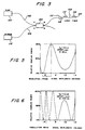
- FIG 2 is a diagram of the absorption spectrum of Nd:YAG crystal at 300°K
- Nd:YAG material has a relatively high optical density, and thus a short absorption length, at selected wavelengths.
- the wavelength of the pumping illumination source it is advisable to select the wavelength of the pumping illumination source in order to permit the absorption length to be as short as possible. This will permit substantially complete absorption of the pumping illumination within a very short length of the Nd:YAG crystal.
- the wavelength 0.58 micron is best suited for pumping illumination
- the wavelength 0.81 micron is preferably selected in the embodiments of the present invention using Nd:YAG crystal as the laser medium.
- Superfluorescent sources have been recently considered as candidates for low temporal coherence sources in many optical applications, in particular fiber gyroscopes and in some signal processing fiber systems.
- a superfluorescent source typically comprises a lasing cylinder end-pumped by a pumping source.
- the pump illumination launched into the lasing cylinder by well known coupling methods is sufficiently intense so as to present conditions leading to ASE.
- the resulting output laser beam is emitted at one end of the lasing cylinder after the beam has traversed the cylinder and undergone amplification by the group of atoms which initially emitted the beam.
- the output beam has characteristics intermediate between a truly coherent laser signal and a completely incoherent thermal source signal.
- the output beam has a low temporal coherence but a fair amount of spatial coherence.
- ASE is characterized by laser theorists as the phenomenon of light emission in which the spontaneous emission coming from a distribution of inverted laser atoms is linearly amplified by the same group of atoms. The gain should be substantial at least in one direction through the atoms. If the laser medium is large enough (long, thin cylinder of inverted atoms), the signal emitted and amplified by these atoms can produce an output beam which can be of high intensity, moderately directional and with very low temporal coherence.
- a source of pumping illumination 100 is coupled to a fiber 102 of a multiplexing coupler 104 to provide pumping illumination at port A of the multiplexing coupler 104.
- the coupler 104 preferably comprises two strands of optical fibers, the uppermost fiber 102 and a lowermost fiber 106.
- the pumping illumination from the source 100 is then transmitted to port B through the coupling action of the coupler 104, as described in further detail hereinbelow.
- the coupler 104 is indeed adjusted to have a 0% coupling efficiency at the wavelength of the source 100.
- An doped fiber 108 preferably an Nd:silica doped fiber, is coupled to port B of the coupler 104 by means of splices or other fiber connecting means 110 (butt joint or fused splice, for example).
- the illumination signal is sufficiently intense to produce amplified spontaneous emission within the doped fiber 108, thereby giving rise to a forward signal 114 and a backward signal 112 as indicated by the arrows in Figure 3.
- the signal emitted in the case of a Nd:silica doped fiber is in a range of wavelengths centered about 1060 nm, the full width at half maximum (FWHM) being generally approximately 17 nm.
- the forward signal 114 exits the doped fiber 108 at the end 120 thereof after travelling one length of the doped fiber 108.
- the backward signal 112 is launched into the coupler 104 at port B and is transmitted to port C through the coupling action of the coupler 104.
- the multiplexing coupler 104 is effectively fabricated for use in this invention to provide complete coupling of the lasing light at 1060 nm, while providing essentially no coupling at the wavelength of the pumping light at 800 nm or another wavelength suited for pumping illumination.
- a mirror or reflector 118 is attached, preferably cemented to the end of the lowermost fiber 106 of the coupler 104. The mirror 118 is designed to provide complete or quasi complete reflection at the wavelength of the output signal.
- the mirror 118 is preferably a dielectric mirror formed of multiple layers of dielectric material.
- the mirror 118 is typically cold-deposited on one end of the fiber 106 or bonded thereto according to techniques well-known in the art. Furthermore, the mirror 118 is selected such that the reflection of the backward signal 112 does not alter the wavelength thereof. The backward signal 112 is thus reflected back to port C and reinjected into port B of the coupler 104 through the same coupling action of the coupler 104. The backward signal 112 travels across the entire length of the doped fiber 108 and exits at the end 120 thereof.
- G is the gain experienced by the signal during its traverse of the doped fiber 108, it is apparent that the forward signal 114 is approximately amplified by a factor e G when it exits the doped fiber 108, whereas the backward signal 112 is amplified by a factor e 2G as it traverses the doped fiber 108 in two directions. If the gain G is high, it is clear that the output signal will be comprised principally of the backward signal 112. Such arrangement is extremely advantageous to increase the intensity of the total output signal.
- reflection occurs only at one end of the doped fiber 108, thereby preventing resonant laser oscillations and preserving the conditions for broadband amplified spontaneous emission.
- the optical system of the present invention therefore provides a convenient means to generate a superfluorescent signal by wavelength dependent coupling of a pump source to a doped fiber, while preventing loss of the backward laser signal by means of a mirror placed at one end of the fiber coupled to the coupler.
- Typical outputs in the order of 10-15 mW have been obtained with a linewidth of about 17 nm (FWHM) in a single mode Nd:SiO 2 fiber pumped near 810 nm with a CW Styryl 9 dye laser. Most of the output consists of the 1060 nm emission.
- the pump source 100 may be a laser diode which permits high concentrations of pump power in the fiber and thus in the doped fiber. Regardless of the type of pumping source utilized, the efficiency of the system will be enhanced if the wavelength of the radiation from the source corresponds with a peak in the absorption spectrum of the doped fiber, for example, of an Nd:silica doped fiber as shown in Figure 2.
- Electroluminescent diodes are commercially available with appropriate dopings to emit light in the 800 nm range. The spectrum of such diodes matches quite well the absorption spectrum of Nd:silica material at room temperature. For example, commercially available Ga(Al)As LEDs provide radiation spectra which are strong in the 800 nm region.
- laser diode structures are commercially available which emit energy over the 850 nm range.
- the pump wavelength should be as close to the signal wavelength as allowed by the spectroscopy of the Nd:silica material to maximize the overall pumping efficiency.
- the preferred embodiment of the present invention utilizes a cw styryl laser dye pump source readily available in the commerce to emit in the range of 800-830 nm.
- Such a laser source coupled into an optic fiber may allow an 80% transmission at the wavelength of the light emitted by the source.
- the FWHM of such a laser pump source is approximately 30 nm.
- the wavelength of the pump source light preferably corresponds to a peak in the absorption spectrum of the lasing material. In the case of Nd, this peak is selected at 804 nm. However, for practical considerations, a proximate wavelength such as 820 nm is acceptable.
- silica is used as the host material of the doped fiber, it has been observed that of the two emission lines of Nd:SiO 2 (900, 1060 nm), only the 1060 nm line reflected by the mirror has large net gain. The 900 nm line is simply self-absorbed in the fiber. Other weaker emission lines may be present but are too weak to be detected by commercial silicon detectors.
- the doped fiber 108 used in the device of the present invention is readily commercially available. It comprises a core, preferably fabricated from a host glass doped with an active laser material and a cladding that surrounds the core.
- the doped fiber 108 includes a core fabricated from a host glass doped with an active laser material and a cladding that surrounds the core.
- the cladding can contain the actual laser material in a thin layer adjacent to the core so that the single-mode light distribution overlaps the active material.
- the preferred active material is neodymium, although other rare earth materials including ytterbium and erbium are likewise suitable.
- the concentration of the dopant in the host glass can vary from a lower limit determined by convenience in length to absorb the pump light and to avoid light loss from excessive lengths required for the particular application and an upper limit determined by concentration quenching. In general, a concentration range between 0.1 and 30% (by weight) is suitable.
- the preferred host glasses include the alkali, alkaline earth silicates, although other silicates, germinates, phosphates and some borate glasses are likewise suitable.
- the index of refraction of the core is selected to be higher than that of cladding so that the pumping light introduced into the core and light emitted by the active material is contained within or in the vicinity of the core.
- the diameter "D" of the core is preferably determined, in part, by the particular application, that is, the diameter of optical fiber into which the light output of the light source 100 is introduced. In general, the diameter of the core is preferably the minimum necessary into which pump light can be efficiently coupled for the particular application to maximize the radiant energy emitted per unit area for a particular pumping light energy level.
- the diameter of the core is selected to give single-mode light transmission at the emission wavelength.
- the diameter of the core depends on the indices of refraction of the core and cladding; a diameter of 1-20 microns, or even up to 50 microns, for wavelengths in the near infrared and visible region of the light spectrum can provide single-mode transmission.
- the diameter of the core can be larger than the minimum for the particular application. For example, where the light source 100 is to be coupled to a single-mode doped fiber having a core diameter of 4 microns, the core can have a somewhat larger diameter, e.g., 6 microns, to facilitate coupling.
- the core size is determined by making ( ⁇ d/ ⁇ )NA equal to or less than 2.4 where d is the core diameter, ⁇ is the wavelength of the emitted light, and NA is the numerical aperture which is related to the indices of refraction of the core and cladding, n 1 and n 2 , by NA equals (n 1 n 2 -n 2 2 ) 1/2 .
- silica or YAG is used as host materials, whereas neodymium or erbium constitute the lasing material.
- the diameter of the doped fiber 108 may be extremely small in comparison with the diameter of Nd:silica rods used in prior art optical systems. For example, an optical system has been constructed wherein the fiber has a diameter of 100 microns. Even smaller diameters are feasible, approaching the diameter of a single-mode fiber. Coupling between the fiber and the crystal in single crystal fiber lasers is enhanced as the diameter of the crystal is reduced and signal gain is increased since density of pumping illumination from the source within the crystal increases as the crystal diameter is reduced.
- doped fibers are numerous and include their high gain, excellent conversion efficiency and interfaceability to single-mode silica fibers, low propagation loss and compactness. A more complete review of the characteristics of doped fibers can be found in U.S. Patent No. 3,456,211 to Koester, issued on July 15, 1969.
- the multiplexing coupler utilized in the preferred embodiment of present invention selectively couples a first optical frequency while not coupling a second optical frequency.
- polished fiber couplers are used.
- Other fiber multiplexers are also suitable, such as fused biconical-taper couplers or integrated optics couplers. Polished fiber couplers, as well as methods for constructing the same, required for such selective coupling are disclosed in U.S. Patent No. 4,556,279, published on December 3, 1985, and listing Herbert J. Shaw and Michael J. F. Digonnet as inventors, assigned to the assignee of the present invention.
- a coupler 210 made of two coupler halves 210a and 210b includes two strands 212a and 212b of a fiber optic material, preferably single-mode fibers, mounted in longitudinal arcuate grooves 213a and 213b, respectively, formed in optically flat confronting surfaces 214a and 214b, respectively, of rectangular bases or blocks 216a and 216b, respectively.
- a fiber optic material preferably single-mode fibers
- Each of the strands 212a, 212b comprise an optical fiber which is doped to have a central core and an outer cladding.
- the strands typically have a core diameter on the order of 5 microns and a cladding diameter on the order of 125 microns.
- the arcuate grooves 213a and 213b have a radius of curvature which is very large compared to the diameter of the fibers 212, and have a width slightly larger than the fibers 212, when mounted therein, to conform to a path defined by the bottom walls of the grooves 213.
- the depth of the grooves 213a and 213b varies from a minimum at the center of the blocks 216a and 216b, respectively, to a maximum at the edges of the blocks 216a and 216b, respectively.
- Fiber optic material was removed from each of the strands 212a and 212b, e.g., by polishing, to form the respective oval-shaped planar surfaces 218a, 218b, which are coplanar with the confronting surfaces 214a, 214b, respectively.
- the amount of fiber optic material removed increases gradually from zero towards the edges of the blocks 216 to a maximum towards the center of the blocks 216.
- This tapered removal of the fiber optic material enables the fiber cores to converge and diverge gradually, which is advantageous for avoiding backward reflection and excess loss of light energy.
- the coupler halves 210a and 210b are identical and are assembled by placing the confronting surfaces 214a and 214b of the blocks 216a and 216b together, so that the confronting surfaces 214a and 214b of the strands 212a and 212b are in facing relationship.
- An index matching substance (not shown), such as index matching oil, is provided between the confronting surfaces 214 in a thin film form.
- An interaction region 232 is formed at the junction of the strands 212, in which light is transferred between the strands by evanescent field coupling. It has been found that, to ensure proper evanescent field coupling, the amount of materials removed from the fibers 212 must be carefully controlled so that the spacing between the core portions of the strands 212 is within a predetermined "critical zone.” The evanescent fields extend into the cladding and decrease rapidly with distance outside their respective cores.
- the blocks or bases 216 may be fabricated of any suitable rigid material.
- evanescent wave polished couplers can have a coupling efficiency of up to 100%.
- these couplers may be "tuned" to adjust the coupling efficiency to any desired value between zero and the maximum.
- tuning may be accomplished, e.g., by relatively laterally sliding the fibers in a direction perpendicular to their length.
- the relative positions of the fibers may be defined in terms of their offset, i.e., the distance between the central axes of the fiber cores, measured in the direction perpendicular to their length, along the confronting surfaces.
- the offset is zero, and the offset increases as the fibers 212 are laterally separated by relatively sliding the blocks 216.
- the coupler 210 illustrated in Figure 4 is highly directional, with substantially all of the power applied at one side of the coupler being delivered to the other side of the coupler.
- the coupler directivity is defined as the ratio of the power at port D to the power at port C, with the input applied to port A.
- the coupler directivity is symmetrical for a given mode of propagation. That is, the coupler operates with the same characteristics regardless of which side of the coupler is the input side and which side is the output side.
- the coupler 210 achieves these results with very low throughput losses.
- the coupler 210 operates on evanescent field coupling principles in which guided modes of the strands 212 interact, through their evanescent fields, to cause light to be transferred between the strands 212. As previously indicated, this transfer of light occurs at the interaction region 232. The amount of light transferred is dependent upon the proximity and orientation of the cores, as well as the effective length of the interaction region 232. As will be described in detail below, the amount of light transferred is also dependent on the wavelength of the light. The length of the interaction region 232 is, in turn, dependent upon the radius of curvature of the fibers 212, and to a limited extent, the core spacing, although it has been found that the effective length of the interaction region 232 is substantially independent of the core spacing.
- the "coupling length,” i.e., the length within the interaction region 232 which is required for a single, complete transfer of a light signal from one fiber 212a to the other 212b, is a function of the core spacing as well as of the wavelength.
- the length of the interaction region 232 is increased, or the core spacing decreased, a phenomenon referred to herein as “overcoupling” will occur, since the coupling length is shorter than the effective interaction length. Under these circumstances, the light will transfer back to the strand from which it originated.
- the effective interaction length increases relative to the coupling length, and at least some of the light transfers back to the other strand.
- the light may make multiple transfers back and forth the two strands 212 as it travels through the region 232, the number of such transfers being dependent on the length of the interaction region 232, the light wavelength (as described below) and the core spacing.
- the coupling length in a fiber coupler typically a monomode fiber as described above, shows a strong dependence on signal wavelength, as described in detail in the aforementioned patents incorporated above, it is possible with properly chosen geometrical parameters for the coupler 210, to totally couple one signal wavelength while a second signal wavelength remains essentially uncoupled. This phenomenon permits the separation of two signals fed into the ports on two sides of the coupler 210.
- both signals can be separated such that the superfluorescent signal is entirely coupled from port B to port C, whereas the pumping signal undergoes no coupling from port A to port B.
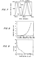
- Figure 5 provides a plot of coupled power versus signal wavelength in the visible and near infrared spectrum for a particular coupler geometry. Because for this coupler configuration the effective interaction length of the coupler is an odd multiple of the coupling length for the selected wavelength 720 mm, but an even multiple of the coupling length for the selected wavelength 550 nm, the wavelength 720 nm will be 100% coupled, while the wavelength 550 nm will be effectively uncoupled. With different efficiencies, different wavelengths may be combined or separated. For instance, 590 nm and 650 nm may be separated or combined at an 80% efficiency.
- Virtually any pair of wavelengths may be efficiently combined or separated so long as the effective interaction length is an even multiple of the coupling length for one wavelength and an odd multiple for coupling length for the other wavelength.
- the resolution of the multiplexer is enhanced by increasing the radius of curvature of the fibers 212a, 212b. Provided that the interaction length of the coupler is large enough, virtually any two signals may be exactly mixed or separated, regardless of how closely spaced their wavelengths are.
- the interaction length is a function of wavelength, and the resolution is approximately proportional to (R) -1/2 , where R is the radius of curvature of the strands 212.
- R is the radius of curvature of the strands 212.
- Figure 6 is comparable to the graph of Figure 5, except that the radius of curvature has been increased to 200 centimeters.
- the resolution of a multiplexing coupler depends on two independent parameters, H (fiber spacing) and R (radius of curvature of the fibers). For a given pair of signal wavelengths, efficient mixing may be achieved by first properly selecting a fiber spacing H for the coupler which yields a large wavelength dependence for the wavelengths of interest (choice of H) and then be selecting a radius of curvature which yields a resolution equal to the difference between the wavelengths (choice of R).
- the coupler may be tuned to precisely adjust the coupling lengths for the wavelengths of interest so that the effective interaction length is an even multiple of the coupling length of one wavelength and an odd multiple of the coupling length of the other wavelength. This is accomplished by offsetting the fibers by sliding the blocks 216a, 216b ( Figure 4) relative one another in a direction normal to the axis of the fibers 212a, 212b. Such an offset has the effect of increasing the minimum fiber spacing H and increasing the effective radius of curvature of the fibers. If the required offset is small enough, it will not upset the multiplexer resolution. This stems from the fact that the separation H of a large radius coupler changes rapidly with fiber offset in comparison to changes in the effective radius of curvature with fiber offset.
- the selective coupling is accomplished in accordance with the technique described above, by properly selecting the fiber spacing H to yield a large wavelength dependence for wavelengths between 0.8 microns and 1.06 microns, and then by selecting a radius of curvature for the fibers which yields a resolution equal to the difference between 1.06 and 0.8 microns, or 0.26 microns.
- the coupler may be tuned as previously described to adjust the coupling length for the wavelengths 0.8 micron and 1.06 microns so that the effective interaction length is an even multiple of the coupling length for one of this pair of wavelengths and an odd multiple of the coupling length for the remaining wavelength.
- the effective interaction length for the coupler should be adjusted to be an odd multiple of the coupling length of the wavelength of the doped fiber, 1.06 microns and to be an even multiple of the source light frequency, 0.8 micron. This will result in a complete coupling of the laser light coming from the doped fiber from the fiber 102 into the fiber 106, with essentially no coupling of the source illumination signal to be transmitted from the fiber 102 to the fiber 106. It will be understood, of course, that no coupling in this instance means an even number of complete couplings so that, for example, if the effective interaction length at the interaction region 232.
- adjustable couplers were used experimentally in embodying the present invention, it will be apparent to a person skilled in the art that other couplers can be used. Adjustable couplers are advantageous inasmuch as they can be readily “tuned” although the index-matching oil used at the interface of the two blocks of an adjustable coupler is prone to thermal dilatation. In many applications, fused couplers may be preferable to adjustable couplers as they are less sensitive to temperature.
- the optical system of the present invention may operate as an amplifier, in accordance with the teachings disclosed in the parent application, U.S. Patent No. 4,674,830.
- the signal to be amplified is selected to have a wavelength at the laser transition wavelength, 1.064 microns, i.e., the wavelength of light emitted by the Nd ions during relaxation between the upper and lower lasing levels.
- the signal to be amplified is injected into the lowermost finer 106 and supplied to the doped fiber 108 by the coupler 104, it will trigger the emission of stimulated photons at the same frequency as the signal, coherent with the signal, and will be thereby amplified.
- the passage of light at this frequency will cause a photon-emitting relaxation between the upper lasing level and lower lasing level as shown in Figures la and lb, in phase with the light signal to be amplified, yielding an effective gain for the input light signal.
- the optical system of the present invention thus functions as an amplifier. In this particular configuration, there is no reflector placed at the end of the lowermost fiber 106. are selected so that the signal can be transmitted through The amplifier signal is output at the end 120 of the doped fiber 108.
- Figure 8 represents a graph of the output power versus estimated absorbed pump power for a superfluorescent source as disclosed in connection with the description of Figure 3.
- the fiber output is essentially unpolarized. At 10 mW output power, the conversion slope efficiency is 45% with a net conversion efficiency between the absorbed pump power and the 1060 nm signal of 12%.
- the output power increases linearly with pump power due to additive spontaneous emission. As stimulated emission becomes significant, the output increases nonlinearly essentially as e 2G , where G is the line center gain experienced by a signal which has travelled the whole length of the device. Placing the mirror 118 at one end of the fiber 106 effectively doubles the active length and, barring any saturation effects, doubles the gain. It should be noted that this is a very large effect as the output now increases as e 2G . The output power drops to about 300 ⁇ W for 80 mW absorbed pump when the mirror 118 is removed.
- Figure 9 shows how the measured linewidth narrows asymptotically due to greater amplification at the peak of the output spectrum and becomes nearly constant at about 16 nm for total output power in the mW range.
- the pump wavelength is selected to be 825 nm.
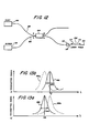
- Figure 10 shows a typical output spectrum of the 1060 nm line with 4.8 mW total power for a pump wavelength of 825 nm.
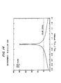
- FIGS. 11a, 11b and 11c there is illustrated the evolution of the gain factor and total fluorescence power along the length of a preferred embodiment of the present invention using a 1% Nd-doped YAG superfluorescent doped fiber.
- Figure 11a shows that at low pump power levels, spontaneous emission dominates and the forward and backward waves P + and P - build up almost linearly.
- the gain factor is essentially unsaturated and decays exponentially from left (input side) to right as a result of pump absorption.
- stimulated emission is dominant and the fluorescence power grows exponentially.
- the fluorescence grows to very large levels near the input and output ends of the fiber, where the gain factor is strongly reduced by population inversion depletion (Figure 11c).
- the gain factor exhibits a sharp maximum near the center of the fiber where the total fluorescence power, which is the sum of the power of the forward signal P + and of the power of the backward signal P - , is minimum.
- the results achieved in the present invention may also be realized using a coupler in which the coupling efficiency at the pumping illumination wavelength is 100%, while the coupling efficiency at the laser output wavelength is 0%.
- Figure 12 is an illustration of such an embodiment.
- the pump source and the mirror are coupled to the coupler similarly to the first embodiment described hereabove in connection with Figure 3.
- the multiplexing coupler of Figure 12 has characteristics different from the coupler 104 of Figure 3, and will be designated by the numeral 304.
- the pump source 100 therefore provides pumping illumination at port A of a multiplexing coupler 304 via a fiber 102, whereas a mirror 118 is coupled to one end of a fiber 106 at port C.
- a doped fiber 108 is coupled at port D in the manner explained in connection with the description of Figure 3.
- the doped fiber 108 is preferably coupled to the optical fiber by means of a splice 110 or may simply be fused to that optical fiber 106.
- Port B is preferably left uncoupled.
- the coupler 304 is adjusted to substantially have a 100% coupling efficiency at the wavelength of the pumping source and a 0% coupling efficiency at the wavelength of the light signal emitted by the doped fiber 108.
- the light from the pumping source 100 is first transmitted along the fiber 102, and coupled from port A to port D into the doped fiber 108.
- the doped fiber preferably an Nd:silica fiber, emits a superfluorescent signal in both the backward and the forward directions as indicated by the arrows 112 and 114 in Figure 22.
- the forward signal 114 is output, uncoupled, to the output end 120 of the doped fiber 108.
- the backward signal 112 is injected back into the coupler 304 at port D and is transmitted to the fiber 106, after being coupled an even number of times through the coupling function of the coupler 304.
- the backward signal 112 is therefore transmitted from port D to port C and is injected into the optical fiber 106 to which is attached to the mirror 118.
- the backward output 112 is therefore reflected back to the coupler 304 through the action of the mirror 118 and transmitted to port D of the coupler 304.
- the backward signal 112 after reflection on the mirror is finally output to the output end 120 of the doped fiber 108.
- the embodiments illustrated hereabove both function according to the same principles.
- One major advantage over the prior art resides in the fact that the pumping illumination is directly launched into the doped fiber without traversing the mirror as was performed heretofore in the prior art.
- the pumping illumination injected into the optic fiber 102 is subsequently coupled through coupling function of the coupler 104 (304) either to port B or to port D depending upon the selected embodiment.
- the pumping signal is never transmitted to the adjacent optic fiber 106 and the mirror 118.
- the pump coupling efficiency is substantially increased. This is particularly advantageous as pump power is critical in generating superfluorescence in the doped fiber.
- the use of the mirror 118 to reflect the superfluorescent signal greatly increases the total gain of the fiber and permits to reduce the power of the pumping source.
- a laser source of output approximately 60-70 mW is typically necessary to obtain a total gain of 9 dB.
- the double passage of the pumping signal by means of the reflector 118 dramatically reduces the required source power by a factor of 2 as a laser source of 30-35 mW is sufficient to obtain the same gain of 9 dB.
- the aforementioned embodiments of the present invention also greatly simplify the coupling process as well as the requirements pertaining to the operation of the mirror.
- the mirror is preferably a high reflector and need not be selected in accordance with other criteria such as its multiplexing properties.
- the pump signal need not traverse a mirror before launching into the doped fiber.
- Various coupling methods can therefore be envisaged to improve the coupling efficiency. This is particularly true for pump sources such as laser diodes whose coupling efficiency is generally low. In the preferred embodiments of the present invention, such efficiency, even with pumping sources such as laser diodes, is greatly improved.
- Coupling techniques well known in the art are therefore applicable to the devices of the present invention. These coupling techniques include, inter alia , tapering the extremity of the fiber at port A.
- Tapered fibers are generally used to channel light from a source or a fiber of comparatively large cross section into a fiber of smaller cross section. By drawing a fiber such that one end thereof has a larger cross section than the other end, it is possible to efficiently couple light emitted by a light source into an optical fiber. Integrated microlenses on the fiber end can also be advantageously used. It is well known in the art that those coupling techniques also improve the frequency stability of the system and more generally ameliorate the performance thereof. A thorough discussion of tapered fibers may be found in Optical Waveguide Theory by Allan Snyder and John Love, Chapman and Hall, 183, London, Great Britain, pp. 107-112.
- mode-matching is also optimized and is substantially better than with regular optical components such as lenses.
- the device thus obtained according to the present invention is very robust, compact and less prone to failure or susceptible to damage during transportation, for example.
- Another major progress over the prior art offered by the aforementioned embodiments of the present invention resides in the particularly advantageous design which permits a separation of the source signal and of the laser signal.
- both the source signal and the laser output travel along the same optical waveguides. It is preferable that the laser light does not return to the pump source nor the coupling optics as such signal propagating towards the cavity of the pumping source may create feedback on the signal path.
- the output laser signal is coupled to the mirror via the coupler either after a 100% transmission through the coupler (first embodiment illustrated in Figure 3) or after a 0% transmission through the coupler (second embodiment illustrated in Figure 12).
- the laser signal therefore does not "see" the cavity of the pump source or the coupling optics, which results in reduced feedback into the signal path emerging from the pump source.
- the coupler thus acts as an isolator by preventing the laser output signal to propagate back to the cavity of the pump source.
- Another and critical advantage of the present invention results from the substantial improvement in the temperature dependence of the superfluorescent source due to the filtering effect produced by the coupler.
- the coupler 104 or 304 in the preferred embodiments respectively illustrated in Figures 3 and 12 advantageously perform at least two important functions. It first acts as a multiplexer insofar as it provides specific routes to the signals propagating therethrough in accordance with the frequencies of these signals. This multiplexing function has been described hereabove in connection with the description of Figures 3 and 12. Furthermore, the coupler used in the present invention is advantageously used to stabilize the superfluorescent signal emitted by the doped fiber 108 against temperature changes.
- a coupler is typically characterized by a filter function which depends on the structural configuration of the coupler.
- Some filter functions representing a coupler power versus signal wavelength were described hereabove in connection with Figures 5, 6 and 7.
- Figure 13a is a diagram illustrating the temperature dependence of a given coupler function. The coupler wavelength dependence function is plotted in Figure 13a using the power transmitted through the coupler ⁇ as the ordinate and the wavelength ⁇ as the abscissa.
- the coefficient ( ⁇ + ⁇ ) is quasi-independent of the glass type and has a value in the order of 10 -5 /°C for all-glass couplers.
- the quantity 1/ ⁇ f ⁇ ⁇ f / ⁇ T is about -10 ppm/°C for an all-glass coupler.
- the thermo-optic coefficient of the coupler is higher. Temperature dependence in the order of several hundreds of ppm/°C is not uncommon in polished fiber couplers.
- the filter linewidth of the coupler may vary from a few angströms (narrow filter) to several hundreds of nanometers (200 nm or so) depending on the fiber selected and the radius of curvature of the fiber.
- the full-width at half maximum (FWHM) is typically represented by ⁇ f and is the line width of the filter function at half the maximum of power transmitted. ⁇ f is indicated in Figure 13a.
- the wavelength of the superfluorescent signal emitted by the fiber source is also dependent upon temperature.
- fiber sources including resonant and non-resonant sources, exhibit an intrinsic wavelength dependence of their emission wavelength ⁇ with respect to temperature characterized by the coefficient ⁇ ⁇ / ⁇ T.
- Figure 13b illustrates the temperature dependence of the emission spectrum of a superfluorescent fiber source in accordance with the present invention.
- the emission spectrum is represented by the curve 402.
- Temperature affects this spectrum by translating it towards the right-hand side so as to yield curve 402a.
- the temperature dependence of a fiber source is in the order of a few ppm per °C (10-20 ppm/°C).
- FWHM full-width at half maximum
- One of the advantages of the present invention is to advantageously use a coupler with selected temperature dependence characteristics so as to at least partially cancel the temperature drift of the emission spectrum.
- Figure 13b shows that the emission spectrum of the fiber source is translated towards the higher wavelengths with a temperature increase; simultaneously, the same temperature increase displaces the multiplexing curve of the coupler towards the lower wavelengths.
- the person skilled in the art will recognize that the quantity in the emission spectrum which should be made stable with respect to temperature is the average spectrum wavelength ⁇ >, rather than the center wavelength ⁇ of the spectrum.
- This average spectrum wavelength ⁇ > is defined by the following expression for a signal emitted by a source and filtered by a multiplexing coupler.
- ⁇ > ⁇ spectrum ⁇ P( ⁇ ) F( ⁇ ) d ⁇ ⁇ spectrum P( ⁇ ) F( ⁇ ) d ⁇ wherein P( ⁇ ) is the emission spectrum function of the source and F( ⁇ ) is the filter function of the coupler.
- the subscript "spectrum" appearing under the integral sign ⁇ refers to the fact that the integrations are performed for the values ⁇ of the emission spectrum.
- Tables 1 and 2 indicate the net improvement obtained by using a coupler as disclosed in the present invention.
- the filter function of the coupler is also assumed not to comprise any sidebands.
- a filter having a function which satisfies these assumptions can be readily achieved by concatenating appropriate fiber couplers.
- suppression of sidebands can be obtained using a bulk optic filter.
- a bulk optic filter has a large temperature dependence (typically in the order of 100 ppm or more per °C), its effect is small as the bulk filter edges are selected to fall near zeroes of the coupler filter function. A shift of the bulk optic filter function thus has little effect on the resulting filter transmission.
- Tables 1 and 2 clearly indicate a net improvement in the temperature dependence of the source when the source signal is preliminarily coupled by means of a multiplexing coupler.
- the net effect of the filter is therefore to reduce variations in the average spectrum wavelength caused by temperature by a factor of about 50 dB.
- the improvement in the temperature dependence of the laser signal is also appreciable in the case of a coupler having a larger temperature dependence (Table 2) and is also in the order of 50 dB.
- Figure 14 is a diagram showing how the improvement varies with respect to the value selected for ⁇ f .
- the ratio ⁇ f / ⁇ f (optimal) is represented on the abscissa axis whereas the improvement ⁇ >/ ⁇ T in dB is represented on the ordinate axis.
- the improvement of the temperature dependence of the source remains substantial (greater than 10 dB) as long as the value of ⁇ f is selected within 10% of its optimal value.
- a coupler in the device of the present invention and adequately selecting the temperature dependence of the coupler within 10% of its optimal value, it is possible to reduce the temperature dependence of the fiber source from a value of 10-20 ppm/°C to 1-2 ppm/°C or better.
- the above theoretical calculations have assumed that the temperature dependence of the coupler is linear.
- the filtering effect of the coupler can be enhanced in the embodiments described hereabove insofar as at least one component of the source signal traverses the coupler twice.
- the device of the present invention is thus extremely advantageous over the prior art as it circumvents many limitations well recognized in the art.
- a coupler such that its temperature dependence varies in the opposite direction of the source spectrum, it is possible to effectively reduce the average wavelength temperature-induced shift of the source spectrum.
- a net improvement as high as 50 dB can be obtained if the temperature dependence of the coupler is properly selected.
- the improvement in the temperature dependence of the source remains however substantial (on the order of 10 dB) if the value of ⁇ f / ⁇ T is selected within 10% of its optimal value.
- the gain is still appreciable (about 3) when the values of ⁇ f / ⁇ T is selected within 30% of its optimal value.
- the value of ⁇ f / ⁇ T is fully compatible with optical couplers presently known.
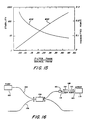
- Figure 15 illustrates the dependence of the stability and of the transmitted power with respect to the ratio of the filter FWHM over the source FWHM.
- the abscissa is represented by this ratio.
- the stability of the superfluorescent output signal is represented whereas the rightmost axis shows the transmitted output power of the superfluorescent signal.
- the filter whose characteristics are plotted in Figure 15 is assumed to be infinitely stable with respect to temperature.
- the increase of output signal stability is by definition the mean wavelength stability for a fixed stable filter function (e.g., a cos 2 function), over an unstable source (e.g., a Lorentzian source).
- the stability curve 600 clearly indicates that the stability of the output signal increases when the filter FWHM decreases for a given source FWHM.
- the output spectrum filtered by a narrower filter (small FWHM) is, therefore, less temperature dependent than the output spectrum filtered by a broader filter (large FWHM).
- the tradeoff for this increase of stability for narrow filtering functions is that less power is transmitted through the coupler, as designed by curve 602.
- the person skilled in the art will indeed recognize that the narrower a filtering function is, the less wavelengths are transmitted and, therefore, the less power is delivered through the coupler.
- the gain which can be achieved in the superfluorescent source of the present invention using an Nd doped fiber is dependent upon the density of the inverted neodymium ion population within the Nd doped fiber.
- Theoretical calculations of the gain signal indicate that the gain factor can be quite large, in the order of 15 dB for a single pass.
- a gain of 15 dB implies that a signal propagating along the laser rod undergoes an amplification by a factor of approximately 31.6.
- the amplification of the forward signal 114 clearly differs from the amplification of the backward signal 112.
- the forward signal 114 is emitted towards the output of the doped fiber rod 108 (rightmost doped fiber end 120) and undergoes an amplification by a factor of g.
- the backward signal 112 undergoes amplification twice, firstly as it exits the doped fiber 108 towards the coupler 104 or 304 and secondly as it re-traverses the doped fiber 108 to be finally output.
- the reflection on the reflector 118 thus allows the amplification of the backward signal 112 to be far superior than the amplification of the forward signal 114.
- the forward signal 112 merely accounts for a small fraction of the total output. However, it is recalled that the filter function of the coupler does not apply to the forward signal 114.
- the forward signal 114 indeed, immediately exits the doped fiber without being filtered by any optical means. If the gain g is sufficiently large, the forward signal 114 is a negligible fraction of the output and therefore the temperature dependence of the unfiltered forward signal 114 does not have a substantial effect on the total output signal.
- the forward signal contribution is significant and, as a result, the temperature dependence of the unfiltered forward signal 114 may influence the temperature function of the total output signal.
- FIG 16 illustrates a schematic representation of the third embodiment according to the present invention.
- the same optical components as described in conjunction with Figures 3 and 12 illustrating the first and second embodiments are utilized in this third embodiment.
- the system therefore comprises a pump source 100, two optical fibers 102 and 106, a doped fiber 108, a mirror 118 and a coupler 104.
- the mirror 118 is placed at one end 120 of the doped fiber 108, whereas the other end 116 of the fiber is coupled to the optical fiber 102, preferably by means of a splice 110, and further coupled to the coupler 104.
- the overall system in the third embodiment thus functions in the following manner.
- the pump source signal is emitted by the pump source 100 and transmitted to the optical fiber 102 as the coupler 104 has been selected not to couple signals at the source wavelength.
- the doped fiber 108 superfluorescence in the conditions described hereabove and yields two components, a forward signal 114 and a backward signal 112 as indicated by the arrows in Figure 16.
- the forward signal 114 (directed towards the left-hand side of the drawing) traverses the coupler 104 and is coupled to the optical fiber 106 as the coupler 104 is selected to 100% couple signals at the laser frequency.
- the output signal is collected on the optical fiber 106.
- the backward signal 112 is reflected by the mirror 118 and output to the optical fiber 106 in the same way as the forward signal 114. It will, however, be recognized that both the forward and the backward signals are filtered once by the coupler.
- the filter function of the coupler can thereby decrease the temperature dependence of the total output signal for the reasons explained hereabove. Therefore, improved temperature stability results from the arrangement illustrated in Figure 16. It is apparent that the net filter function of the output signal in the third embodiment of the present invention is different from the filter function in the first two embodiments illustrated in Figures 3 and 12.
- the total output signal in the system of Figure 16 is indeed filtered once, whereas in the first and second embodiments, the backward component solely is filtered twice and the forward component remains unfiltered. All the advantages described in connection with the first two embodiments still apply to this third embodiment.
- FIG. 17 Another embodiment corresponding to the coupling arrangement described in conjunction with Figure 12 is also envisionable.
- the properties of the coupler 304 are selected so that the coupler totally couples the pump source signal wavelength and essentially does not couple the laser signal wavelength.
- the doped fiber 108 and the mirror 118 are therefore coupled to the port D of the coupler 304.
- the pump signal is totally coupled to the doped fiber 108 via the coupler 304.
- the forward and backward components of the emitted laser signal are essentially uncoupled and transmitted to the optical fiber 106. All the advantages inherent to the previous embodiments are still valid (temperature dependence in particular).
- a fifth embodiment using an all-fiber reflector incorporating a gyroscope-like loop of fiber can also be envisioned.
- All-fiber reflectors are known in the art.
- a Nd 3+ doped cw fiber laser using all-fiber reflectors is disclosed in an article by J. D. Miller, et al., entitled "A Nd 3+ -doped cw fiber laser using all-fiber reflectors," Applied Optics , Vol. 26, No. 11, pp. 2197-2201, June 1, 1987.
- Fiber reflectors are produced by looping back the outputs of a directional coupler.
- a passive all-fiber mirror has properties different from those of a typical dielectric or metal reflector. Light incident on the coupler is divided so that two portions of the field travel around the coupler in opposite directions. Light which couples across the coupler undergoes a ⁇ /2 phase lag.
- Figure 18 is a schematic representation of an all-fiber mirror.
- the elements described in connection with Figures 3 and 12 are designated by the same numerals.
- a fiber 102 preferably a single-mode fiber, is used and looped back between two adjacent ports of a coupler 704.
- the coupler 704 is preferably a fused coupler.
- An input signal is injected from a source 100 into one port of the coupler 704.
- One component I 1 of the input signal does not cross the coupler 704 and circulates the loop counterclockwise.
- the other component I 2 circulates the loop counterclockwise with two cross-traverses of the coupler 704.
- a pump source 100 is coupled to the fiber 102 of the coupler 704 to provide pumping illumination at port A of the multiplexing coupler 704.
- the optical fiber 102 at ports B and D is looped back in the manner described hereabove so as to form an all-fiber reflector.
- the fiber 102 at port C is coupled, e.g., butt-jointed or splice-fused, to a doped fiber 108 such as the one used in the previous embodiments.
- the doped fiber 108 is a neodymium glass fiber (NGF).
- NGF neodymium glass fiber
- the geometrical parameters of the coupler are further selected so that the coupling ratio is 0.5 at the center wavelength of the doped fiber emission (corresponding to a coupling ratio of 3 dB) and so that the coupling ratio is 0 for the wavelength pump.
- the pump signal is therefore fully transmitted by the loop and fully coupled to the doped fiber.
- the reflected laser signal thus undergoes a ⁇ /2 phase change as shown in the above theoretical calculation regarding all-fiber reflectors.
- Equations (11) and (12) Two results can be inferred from Equations (11) and (12).
- An all-fiber reflector with low losses can give close to complete reflection.
- one of the important features of the present invention resides in the filter function performed by the multiplexing coupler.
- Such filter function allows a greater temperature stability. It is possible to replace the multiplexing coupler used in the previous embodiments with an optical filter whose parameters have been properly selected with regard to transmission at particular wavelengths.
- Figures 19 and 20 represent in a schematic way, in the form of a block diagram, the two further embodiments according to the present invention.
- FIGs 19 and 20 four blocks are represented, illustrating respectively a pump 100, a high reflectance mirror 118, a doped fiber 108 and a filter 804 having a selected temperature dependence.
- the system illustrated in Figure 19 operates in the following manner.
- a pump source 100 emits a light signal illuminating a mirror 118.
- the mirror 118 is chosen to be transparent to the pump source wavelength.
- the mirror 118 is further coupled to a doped fiber 108.
- the transmitted pump signal illuminates the fiber 108, preferably an Nd:glass fiber (NGF), and produces superfluorescence if adequate pumping conditions are met.
- the laser signal has two components, a forward component 114 which is output at one end of the doped fiber 108 and a backward component 112.
- the mirror 118 is made reflective for the backward component wavelength and the backward component 112 is reflected back towards the output end of the doped fiber 108.
- the output laser signal is subsequently filtered by the filter 804 so that it becomes less temperature sensitive.
- the temperature dependence of the filter is selected such that a signal emitted by the fiber source and filtered by the filter has a lower temperature dependence than an unfiltered laser signal.
- the filter 804 is positioned between the mirror 118 and the doped fiber 108.
- the backward component 112 only is filtered by the filter 804.
- the backward component 112 traverses the filter 804 twice, the first time en route towards the mirror 118 and the second time on its way back to the output end of the doped fiber 108. This embodiment is particularly advantageous if the gain of the doped fiber is sufficiently high.
- a variety of filters can be used in the embodiments illustrated in Figures 19 and 20. As indicated in the disclosure of the previous embodiments, a multiplexing coupler is well suited to act as a filter. However, any filter susceptible to decrease the temperature dependence of the superfluorescent output signal would be adequate.
- the superfluorescent nature of the output signal emitted by the fiber source does not play a role in the filtering effect produced by the filter, and thus the concepts discussed herein are broadly applicable to other types of light signals.
- the emission spectrum of the fiber source can have a broad bandwidth as in the preferred embodiments of the present invention or have a narrower bandwidth.
- the preferred embodiments of the present invention have been described using polished optical fiber couplers. It will also be understood that other types of couplers of the state of the art can be used such as integrated optics couplers, biconical-taper fused couplers, etc.
Landscapes
- Physics & Mathematics (AREA)
- Electromagnetism (AREA)
- Engineering & Computer Science (AREA)
- Plasma & Fusion (AREA)
- Optics & Photonics (AREA)
- Lasers (AREA)
- Light Guides In General And Applications Therefor (AREA)
- Gyroscopes (AREA)
- Optical Fibers, Optical Fiber Cores, And Optical Fiber Bundles (AREA)
Claims (32)
- Faseroptiksystem mit:gekennzeichnet durcheiner Pumpquelle (100) zum Emittieren von Pumplicht mit einem ersten Wellenlängenspektrum;einer mit Lasermaterial dotierten optischen Faser (108), wobei die Intensität des Pumplichts in dem ersten Wellenlängenspektrum ausreicht, um superfluoreszente Emission von Laserlicht in dem Lasermaterial bei einem zweiten Wellenlängenspektrum zu induzieren; und wobei das Laserlicht ein Vorwärtssignal (114) und ein Rückwärtssignal (112) aufweist, die an den Stellen, wo das Laserlicht emittiert wird, im wesentlichen einander entgegengerichtet sind,einen Multiplexkuppler (104) zum Leiten von durch die Pumpquelle (100) emittiertem Licht mit dem ersten Wellenlängenspektrum in ein Ende der dotierten Faser (108), wobei die Intensität dieses Pumplichtes ausreicht, um die Emission von superfluoreszentem Licht mit dem zweiten Wellenlängenspektrum in dem Lasermaterial zu induzieren, und wobei der Multiplexkuppler (104) für das erste Wellenlängenspektrum einen anderen Kupplungswirkungsgrad hat als für das zweite Wellenlängenspektrum;einen an den Multiplexkuppler (104) gekuppelten Reflektor (118), um das Vorwärtssignal (114) und/oder das Rückwärtssignal (112) in und durch den Multiplexkuppler (104) zu reflektieren; undeine für den Multiplexkuppler (104) gewählte niedrige Temperaturabhängigkeit, um die Temperaturverschiebung des Emissionsspektrums aufzuheben, so daß das von dem Multiplexkuppler (104) gefilterte Laserlicht weniger temperaturabhängig ist als das ungefilterte Laserlicht.
- Faseroptiksystem nach Anspruch 1, bei dem der Multiplexkuppler (104) ein im wesentlichen vollständiges Kuppeln des Pumplichtes bei dem ersten Wellenlängenspektrum bewirkt und ein Kuppeln des Laserlichts bei dem zweiten Wellenlängenspektrum im wesentlichen hemmt.
- Faseroptiksystem nach Anspruch 1, bei dem der Multiplexkuppler (104) ein im wesentlichen vollständiges Kuppeln des Laserlichtes bei dem zweiten Wellenlängenspektrum bewirkt und ein Kuppeln des Pumplichts bei dem ersten Wellenlängenspektrum im wesentlichen hemmt.
- Faseroptiksystem nach Anspruch 1, bei dem der Multiplexkuppler (104) ein im wesentlichen 50%iges Kuppeln des Laserlichts bei dem zweiten Wellenlängenspektrum bewirkt und ein Kuppeln des Pumplichtes bei dem ersten Wellenlängenspektrum im wesentlichen hemmt.
- Faseroptiksystem nach Anspruch 1, bei dem der Reflektor (118) an ein zweites Ende der dotierten optischen Faser (108) gekuppelt ist, wobei das Laserlicht aus der dotierten Faser (108) über das erste Ende der dotierten Faser (108) austritt.
- Faseroptiksystem nach Anspruch 1, bei dem das Laserlicht aus der dotierten Faser (108) über den Multiplexkuppler (104) an einem anderen Anschluß des Kupplers (104) austritt.
- Faseroptiksystem nach Anspruch 1, bei dem der Multiplexkuppler (104) einen dritten und einen vierten Anschluß hat und bei dem der Reflektor (118) eine optische Faser aufweist, die eine Schleife zwischen dem dritten und dem vierten Anschluß bildet.
- Faseroptiksystem nach einem der vorherigen Ansprüche, bei dem die dotierten optische Faser (108) eine mit dem Lasermaterial dotierte Einfachmodus-Faser ist.
- Faseroptiksystem nach einem der vorherigen Ansprüche, bei dem das Kuppeln von Licht in dem Multiplexkuppler (104) evaneszenter Feldkupplung unterliegt.
- Faseroptiksystem nach einem der vorherigen Ansprüche, bei dem das erste Wellenlängenspektrum im wesentlichen die Wellenlänge bei 806 nm umfaßt.
- Faseroptiksystem nach einem der vorherigen Ansprüche, bei dem das zweite Wellenlängenspektrum im wesentlichen die Wellenlänge bei 1060 nm umfaßt.
- Faseroptiksystem nach einem der vorherigen Ansprüche, bei dem das Lasermaterial ein Ion der Seltenen Erden enthält und die dotierte optische Faser (108) aus einem Wirtsglas aus einer Gruppe besteht, die im wesentlichen Alkali, Erdalkalisilikate, Silikate, Keime, Phosphate oder Boratgläser enthält.
- Faseroptiksystem nach Anspruch 12, bei dem das Material der seltenen Erde vorzugsweise Neodym, Ytterbium oder Erbium ist.
- Faseroptiksystem nach einem der vorherigen Ansprüche, bei dem die dotierte optische Faser (108) an eine optische Faser angeschmolzen oder gespleißt ist, um sie mit dem zweiten Anschluß des Multiplexkupplers (104) zu kuppeln.
- Faseroptiksystem nach Anspruch 1, bei dem der Reflektor (118) einen dielektrischen Spiegel aufweist.
- Faseroptiksystem nach Anspruch 1, bei dem der Reflektor (118) einen metallischen Spiegel aufweist.
- Faseroptiksystem nach einem der vorherigen Ansprüche, bei dem die Quelle (100) eine Laserdiode ist.
- Faseroptiksystem nach einem der vorherigen Ansprüche, bei dem die Quelle (100) ein Farbstofflaser ist.
- Faseroptiksystem nach einem der vorherigen Ansprüche, bei dem das mit dem zweiten Frequenzspektrum emittierte Licht eine große Bandbreite aufweist.
- Faseroptiksystem nach Anspruch 1, bei dem der Multiplexkuppler (104) eine erste und eine zweite Länge einer optischen Faser nebeneinanderliegend aufweist, um ein Kuppeln von Licht zwischen der ersten und der zweiten Länge zu bewirken, wobei die erste und die zweite Länge der optischen Faser einen ersten Endteil und einen zweiten Endteil besitzen, die Pumpquelle (100) an den ersten Endteil der ersten Länge der optischen Faser gekuppelt ist, die erste und die zweite Länge der optischen Faser einen einfachen, durchgehenden Strang einer optischen Faser bilden, und der optische Faserstrang einen Schleifenbereich und zwei Linienbereiche bildet, die mit der Pumpquelle (100) bzw. der dotierten optischen Faser (108) verbunden sind.
- Faseroptiksystem mit:einer Pumpquelle (100) zum Emittieren von Pumplicht mit einem ersten Wellenlängenspektrum;einer mit Lasermaterial dotierten optischen Faser (108), wobei die Intensität des Pumplichts ausreicht, um die Emission von superfluoreszentem Laserlicht in dem Lasermaterial bei einem zweiten Wellenlängenspektrum zu induzieren, wenn das Lasermaterial mit dem Pumplicht gepumpt wird, wobei der Laserlicht wenigstens ein Vorwärtssignal (114) und ein Rückwärtssignal (112) aufweist; und einem Reflektor (118) zum Reflektieren der ersten und/oder der zweiten Komponente des Laserlichts, gekennzeichnet durcheinen optischen Filter (804) zum Filtern des Vorwärtsund/oder des Rückwärtssignals (114, 112), wobei der Filter mit einer niedrigen Temperaturabhängigkeit ausgewählt ist, um die Temperaturverschiebung des Emissionsspektrums zu hemmen, so daß das von dem optischen Filter (804) gefilterte Laserlicht weniger temperaturabhängig ist als das ungefilterte Laserlicht.
- Faseroptiksystem nach Anspruch 21, bei dem der Reflektor (118) zwischen die Pumpquelle (100) und die dotierte optische Faser (108) eingefügt ist, wobei der Reflektor (118) selektiv das Pumplicht in dem ersten Wellenlängenspektrum durchläßt und das Laserlicht in dem zweiten Wellenlängenspektrum reflektiert.
- Faseroptiksystem nach Anspruch 21, bei dem die dotierte optische Faser (108) zwischen den Reflektor (118) und den optischen Filter (804) eingefügt ist.
- Faseroptiksystem nach Anspruch 21, bei dem der optische Filter (804) zwischen den Reflektor (118) und die dotierte optische Faser (108) eingefügt ist.
- Faseroptiksystem nach Anspruch 21, weiterhin mit einem zweiten Reflektor (118) zum Bilden eines Resonanzraums in der dotierten optischen Faser (108).
- Faseroptiksystem nach Anspruch 21, bei dem das Laserlicht eine große Bandbreite aufweist.
- Faseroptiksystem nach Anspruch 21, bei dem das Laserlicht eine enge Bandbreite aufweist.
- Verfahren zum Erzeugen von Licht geringer zeitlicher Kohärenz, mit folgenden Schritten:Vorsehen einer Quelle (100) zur Pumpbelichtung bei einem ersten Wellenlängenspektrum;Pumpen eines Endes einer mit Lasermaterial dotierten optischen Faser (108) mit der Pumpbelichtung, um eine Emission von superfluoreszentem Licht in dem Lasermaterial bei einem zweiten Wellenlängenspektrum zu erzeugen, wobei das superfluoreszente Licht wenigstens ein Vorwärtssignal (114) und ein Rückwärtssignal (112) aufweist, gekennzeichnet durch folgende Schritte:Multiplexen des Pumplichts und des superfluoreszenten Lichts in einem optischen Kuppler (104), der mit der dotierten optischen Faser (108) und der Quelle (100) verbunden ist und für das erste Wellenlängenspektrum und das zweite Wellenlängenspektrum einen unterschiedlichen Kupplungswirkungsgrad aufweist, und Reflektieren des Vorwärts-und/oder des Rückwärtssignals in und durch den optischen Kuppler (104);Auswählen des optischen Kupplers (104) mit einer niedrigen Temperaturabhängigkeit, um die Temperaturverschiebung des Emissionsspektrums aufzuheben, so daß das von dem optischen Kuppler (104) gefilterte Laserlicht weniger temperaturabhängig ist als das ungefilterte Laserlicht.
- Verfahren zum Erzeugen von Licht geringer zeitlicher Kohärenz nach Anspruch 28, mit dem weiteren Schritt das Leitens der reflektierten Komponente in die dotierte optische Faser (108).
- Verfahren zum Erzeugen von superfluoreszentem Licht mit geringer zeitlicher Kohärenz und geringer Temperaturabhängigkeit, mit folgenden Schritten:Vorsehen einer Quelle (100) zur Pumpbelichtung bei einem ersten Wellenlängenspektrum;Pumpen einer mit Lasermaterial dotierten optischen Faser (108) mit der Pumpbelichtung, um eine Emission von Laserlicht in dem Lasermaterial bei einem zweiten Wellenlängenspektrum zu erzeugen, wobei das Laserlicht wenigsten eine Vorwärtskomponente und eine Rückwärtskomponente aufweist; undReflektieren der Vorwärts- und/oder der Rückwärtskomponente in die dotierte optische Faser (108) zurück, gekennzeichnet durch folgende Schritte:Filtern der ersten und/oder der zweiten Komponente des Laserlichts mittels eines optischen Filters (804) mit einer ausgewählten Temperaturabhängigkeit, um die Temperaturverschiebung des Emissionsspektrums aufzuheben, so daß die gefilterte Komponente eine geringere Temperaturabhängigkeit aufweist als das ungefilterte Licht.
- Verfahren zum Erzeugen von Licht geringer zeitlicher Kohärenz nach Anspruch 30, bei dem der Schritt des Pumpens den Schritt umfaßt, in der dotierten Faser (108) Superfluoreszenz zu induzieren.
- Verfahren zum Erzeugen von Licht geringer zeitlicher Kohärenz nach Anspruch 30, bei dem der Schritt des Filterns folgende Schritte umfaßt:Vorsehen eines optischen Kupplers (104) mit einer vorgegebenen zweiten Temperaturverschiebung, die mit der ersten Temperaturverschiebung des Laserlichts im wesentlichen gleich und dieser entgegengerichtet ist; undKuppeln der Vorwärts- und/oder der Rückwärtskomponente des Laserlichts mittels des optischen Kupplers (104) zum Erzeugen einer gekuppelten Komponente mit einer dritten Temperaturverschiebung, wobei die dritte Temperaturverschiebung der gekuppelten Komponente im wesentlichen aufgehoben oder minimiert wird.
Priority Applications (1)
| Application Number | Priority Date | Filing Date | Title |
|---|---|---|---|
| EP97111612A EP0817335B1 (de) | 1988-12-07 | 1989-12-05 | Breitbandige Superfluoreszenz-Faserlaserquelle |
Applications Claiming Priority (2)
| Application Number | Priority Date | Filing Date | Title |
|---|---|---|---|
| US07/281,088 US4938556A (en) | 1983-11-25 | 1988-12-07 | Superfluorescent broadband fiber laser source |
| US281088 | 1988-12-07 |
Related Child Applications (1)
| Application Number | Title | Priority Date | Filing Date |
|---|---|---|---|
| EP97111612A Division EP0817335B1 (de) | 1988-12-07 | 1989-12-05 | Breitbandige Superfluoreszenz-Faserlaserquelle |
Publications (3)
| Publication Number | Publication Date |
|---|---|
| EP0372907A2 EP0372907A2 (de) | 1990-06-13 |
| EP0372907A3 EP0372907A3 (de) | 1991-07-24 |
| EP0372907B1 true EP0372907B1 (de) | 1998-06-17 |
Family
ID=23075910
Family Applications (1)
| Application Number | Title | Priority Date | Filing Date |
|---|---|---|---|
| EP89312666A Expired - Lifetime EP0372907B1 (de) | 1988-12-07 | 1989-12-05 | Breitbandige Superfluoreszenz-Faserlaserquelle |
Country Status (5)
| Country | Link |
|---|---|
| EP (1) | EP0372907B1 (de) |
| JP (1) | JPH07117669B2 (de) |
| KR (1) | KR100256435B1 (de) |
| CA (1) | CA2004716C (de) |
| DE (2) | DE68928713T2 (de) |
Families Citing this family (10)
| Publication number | Priority date | Publication date | Assignee | Title |
|---|---|---|---|---|
| US5268910A (en) * | 1991-07-18 | 1993-12-07 | General Instrument Corporation | Superluminescent optical source |
| US5191586A (en) * | 1991-07-18 | 1993-03-02 | General Instrument Corporation | Narrow band incoherent optical carrier generator |
| US5272560A (en) * | 1992-03-30 | 1993-12-21 | Hewlett-Packard Company | Variable spectral width multiple pass optical noise source |
| FR2736732B1 (fr) * | 1995-07-13 | 1997-10-03 | Photonetics | Source de lumiere a spectre large stabilise |
| US6867910B2 (en) | 2001-04-24 | 2005-03-15 | Kyocera Corporation | Wideband ASE light source |
| US7738109B2 (en) | 2002-08-20 | 2010-06-15 | The Board Of Trustees Of The Leland Stanford Junior University | Fiber optic sensor using a Bragg fiber |
| US20040061863A1 (en) * | 2002-08-20 | 2004-04-01 | Digonnet Michel J.F. | Fiber optic sensors with reduced noise |
| US6888981B2 (en) | 2002-09-13 | 2005-05-03 | Honeywell International Inc. | Wavelength division multiplexing coupler with loss element |
| JP2007206127A (ja) * | 2006-01-31 | 2007-08-16 | Nec Corp | 光反射器、及びそれを用いた光共振器、並びにそれを用いたレーザ |
| EP2035782A2 (de) | 2006-06-29 | 2009-03-18 | The Board of Trustees of The Leland Stanford Junior University | Glasfasersensor mit einer bragg-faser |
Family Cites Families (6)
| Publication number | Priority date | Publication date | Assignee | Title |
|---|---|---|---|---|
| US4515431A (en) * | 1982-08-11 | 1985-05-07 | The Board Of Trustees Of The Leland Stanford Junior University | Fiber optic amplifier |
| US4674830A (en) * | 1983-11-25 | 1987-06-23 | The Board Of Trustees Of The Leland Stanford Junior University | Fiber optic amplifier |
| US4637025A (en) * | 1984-10-22 | 1987-01-13 | Polaroid Corporation | Super radiant light source |
| FR2573547B1 (fr) * | 1984-11-16 | 1987-04-10 | Thomson Csf | Source optique monomode et dispositif amplificateur optique accordables dans le proche infra-rouge et l'application aux dispositifs amplificateurs selectifs et de regeneration |
| JPS63260189A (ja) * | 1987-04-17 | 1988-10-27 | Nippon Telegr & Teleph Corp <Ntt> | 光ソリトンフアイバレ−ザ |
| US4748631A (en) * | 1987-05-06 | 1988-05-31 | International Business Machines | Modulated laser source for optical storage |
-
1989
- 1989-12-05 DE DE68928713T patent/DE68928713T2/de not_active Expired - Fee Related
- 1989-12-05 EP EP89312666A patent/EP0372907B1/de not_active Expired - Lifetime
- 1989-12-05 DE DE68929397T patent/DE68929397T2/de not_active Expired - Fee Related
- 1989-12-06 CA CA002004716A patent/CA2004716C/en not_active Expired - Lifetime
- 1989-12-07 KR KR1019890018257A patent/KR100256435B1/ko not_active IP Right Cessation
- 1989-12-07 JP JP1320351A patent/JPH07117669B2/ja not_active Expired - Lifetime
Also Published As
| Publication number | Publication date |
|---|---|
| DE68928713D1 (de) | 1998-07-23 |
| KR100256435B1 (ko) | 2000-05-15 |
| CA2004716C (en) | 1999-02-23 |
| EP0372907A3 (de) | 1991-07-24 |
| EP0372907A2 (de) | 1990-06-13 |
| JPH07117669B2 (ja) | 1995-12-18 |
| JPH0328830A (ja) | 1991-02-07 |
| DE68929397D1 (de) | 2002-06-13 |
| DE68928713T2 (de) | 1998-10-29 |
| KR900011082A (ko) | 1990-07-11 |
| CA2004716A1 (en) | 1990-06-07 |
| DE68929397T2 (de) | 2002-12-19 |
Similar Documents
| Publication | Publication Date | Title |
|---|---|---|
| US4938556A (en) | Superfluorescent broadband fiber laser source | |
| US4964131A (en) | Broadband optical fiber laser | |
| US6487233B2 (en) | Fiber-coupled microsphere laser | |
| US4637025A (en) | Super radiant light source | |
| US4553238A (en) | Fiber optic amplifier | |
| US6041072A (en) | Apparatus for stabilizing multiple laser sources and their application | |
| US5659644A (en) | Fiber light source with multimode fiber coupler | |
| US5108183A (en) | Interferometer utilizing superfluorescent optical source | |
| US4829529A (en) | Laser diode pumped fiber lasers with pump cavity | |
| US4815804A (en) | In-line fiber optic memory and method of using same | |
| NO844512L (no) | Fiberoptisk forsterker | |
| US6859582B2 (en) | Dual-wavelength hybrid waveguide coupler | |
| NO834544L (no) | Fiberoptisk forsterker | |
| JP2000036630A (ja) | 光信号源 | |
| US5448586A (en) | Pumping arrangements for arrays of planar optical devices | |
| US4708421A (en) | In-line fiber optic memory | |
| US6282016B1 (en) | Polarization maintaining fiber lasers and amplifiers | |
| EP0372907B1 (de) | Breitbandige Superfluoreszenz-Faserlaserquelle | |
| CN100588056C (zh) | 单频单偏振线性腔掺镱光纤激光器 | |
| CN108988106A (zh) | 基于超表面外腔镜的可控多波长光纤外腔激光器 | |
| EP0817335B1 (de) | Breitbandige Superfluoreszenz-Faserlaserquelle | |
| CN109560453A (zh) | 基于sbs和法布里珀罗干涉仪的被动调q锁模环形激光器 | |
| EP0366756B1 (de) | Optische faser-breitbandlaser | |
| US6556343B1 (en) | Optical fiber device | |
| Babin et al. | Broadly tunable high-power random fibre laser |
Legal Events
| Date | Code | Title | Description |
|---|---|---|---|
| PUAI | Public reference made under article 153(3) epc to a published international application that has entered the european phase |
Free format text: ORIGINAL CODE: 0009012 |
|
| AK | Designated contracting states |
Kind code of ref document: A2 Designated state(s): DE FR GB IT |
|
| PUAL | Search report despatched |
Free format text: ORIGINAL CODE: 0009013 |
|
| AK | Designated contracting states |
Kind code of ref document: A3 Designated state(s): DE FR GB IT |
|
| 17P | Request for examination filed |
Effective date: 19920121 |
|
| 17Q | First examination report despatched |
Effective date: 19930819 |
|
| GRAG | Despatch of communication of intention to grant |
Free format text: ORIGINAL CODE: EPIDOS AGRA |
|
| GRAH | Despatch of communication of intention to grant a patent |
Free format text: ORIGINAL CODE: EPIDOS IGRA |
|
| GRAH | Despatch of communication of intention to grant a patent |
Free format text: ORIGINAL CODE: EPIDOS IGRA |
|
| GRAH | Despatch of communication of intention to grant a patent |
Free format text: ORIGINAL CODE: EPIDOS IGRA |
|
| GRAA | (expected) grant |
Free format text: ORIGINAL CODE: 0009210 |
|
| AK | Designated contracting states |
Kind code of ref document: B1 Designated state(s): DE FR GB IT |
|
| DX | Miscellaneous (deleted) | ||
| REF | Corresponds to: |
Ref document number: 68928713 Country of ref document: DE Date of ref document: 19980723 |
|
| ITF | It: translation for a ep patent filed | ||
| ET | Fr: translation filed | ||
| PLBE | No opposition filed within time limit |
Free format text: ORIGINAL CODE: 0009261 |
|
| STAA | Information on the status of an ep patent application or granted ep patent |
Free format text: STATUS: NO OPPOSITION FILED WITHIN TIME LIMIT |
|
| 26N | No opposition filed | ||
| REG | Reference to a national code |
Ref country code: GB Ref legal event code: IF02 |
|
| PGFP | Annual fee paid to national office [announced via postgrant information from national office to epo] |
Ref country code: IT Payment date: 20071229 Year of fee payment: 19 Ref country code: DE Payment date: 20080131 Year of fee payment: 19 |
|
| PGFP | Annual fee paid to national office [announced via postgrant information from national office to epo] |
Ref country code: FR Payment date: 20081212 Year of fee payment: 20 |
|
| PGFP | Annual fee paid to national office [announced via postgrant information from national office to epo] |
Ref country code: GB Payment date: 20081216 Year of fee payment: 20 |
|
| PG25 | Lapsed in a contracting state [announced via postgrant information from national office to epo] |
Ref country code: DE Free format text: LAPSE BECAUSE OF NON-PAYMENT OF DUE FEES Effective date: 20090701 |
|
| REG | Reference to a national code |
Ref country code: GB Ref legal event code: PE20 Expiry date: 20091204 |
|
| PG25 | Lapsed in a contracting state [announced via postgrant information from national office to epo] |
Ref country code: GB Free format text: LAPSE BECAUSE OF EXPIRATION OF PROTECTION Effective date: 20091204 |
|
| PG25 | Lapsed in a contracting state [announced via postgrant information from national office to epo] |
Ref country code: IT Free format text: LAPSE BECAUSE OF NON-PAYMENT OF DUE FEES Effective date: 20081205 |