EP0372834B1 - Méthode de traduction - Google Patents
Méthode de traduction Download PDFInfo
- Publication number
- EP0372834B1 EP0372834B1 EP89312500A EP89312500A EP0372834B1 EP 0372834 B1 EP0372834 B1 EP 0372834B1 EP 89312500 A EP89312500 A EP 89312500A EP 89312500 A EP89312500 A EP 89312500A EP 0372834 B1 EP0372834 B1 EP 0372834B1
- Authority
- EP
- European Patent Office
- Prior art keywords
- computer system
- software
- target computer
- source
- translated
- Prior art date
- Legal status (The legal status is an assumption and is not a legal conclusion. Google has not performed a legal analysis and makes no representation as to the accuracy of the status listed.)
- Expired - Lifetime
Links
- 238000000034 method Methods 0.000 title claims description 141
- 238000013519 translation Methods 0.000 title claims description 62
- 238000004088 simulation Methods 0.000 claims description 24
- 230000004044 response Effects 0.000 claims description 9
- 238000012544 monitoring process Methods 0.000 claims 6
- 230000014616 translation Effects 0.000 description 65
- 230000000694 effects Effects 0.000 description 52
- 230000008569 process Effects 0.000 description 33
- 238000012545 processing Methods 0.000 description 32
- 238000005457 optimization Methods 0.000 description 28
- 238000003379 elimination reaction Methods 0.000 description 26
- 230000008030 elimination Effects 0.000 description 25
- 238000013507 mapping Methods 0.000 description 22
- 238000013459 approach Methods 0.000 description 21
- 230000009466 transformation Effects 0.000 description 21
- 238000005206 flow analysis Methods 0.000 description 20
- 230000006870 function Effects 0.000 description 15
- 238000004364 calculation method Methods 0.000 description 12
- 238000004458 analytical method Methods 0.000 description 11
- 238000000844 transformation Methods 0.000 description 11
- 230000008901 benefit Effects 0.000 description 10
- 230000009290 primary effect Effects 0.000 description 10
- 238000011161 development Methods 0.000 description 9
- 230000015572 biosynthetic process Effects 0.000 description 7
- 238000003786 synthesis reaction Methods 0.000 description 7
- 238000005516 engineering process Methods 0.000 description 6
- 230000002093 peripheral effect Effects 0.000 description 6
- 230000009471 action Effects 0.000 description 5
- 230000008859 change Effects 0.000 description 5
- 238000006243 chemical reaction Methods 0.000 description 4
- 238000013461 design Methods 0.000 description 4
- 238000003860 storage Methods 0.000 description 4
- 238000012360 testing method Methods 0.000 description 4
- 230000001419 dependent effect Effects 0.000 description 3
- 238000010586 diagram Methods 0.000 description 3
- 239000013598 vector Substances 0.000 description 3
- 239000012634 fragment Substances 0.000 description 2
- 230000003993 interaction Effects 0.000 description 2
- 230000007246 mechanism Effects 0.000 description 2
- 238000003909 pattern recognition Methods 0.000 description 2
- 238000000638 solvent extraction Methods 0.000 description 2
- 238000001228 spectrum Methods 0.000 description 2
- 208000010543 22q11.2 deletion syndrome Diseases 0.000 description 1
- 230000006399 behavior Effects 0.000 description 1
- 239000006227 byproduct Substances 0.000 description 1
- 230000015556 catabolic process Effects 0.000 description 1
- 238000004891 communication Methods 0.000 description 1
- 238000004590 computer program Methods 0.000 description 1
- 238000007796 conventional method Methods 0.000 description 1
- 238000012937 correction Methods 0.000 description 1
- 238000007405 data analysis Methods 0.000 description 1
- 238000006731 degradation reaction Methods 0.000 description 1
- 238000004880 explosion Methods 0.000 description 1
- 239000002360 explosive Substances 0.000 description 1
- 238000004519 manufacturing process Methods 0.000 description 1
- 230000003278 mimic effect Effects 0.000 description 1
- 239000000047 product Substances 0.000 description 1
- 230000009467 reduction Effects 0.000 description 1
- 238000009877 rendering Methods 0.000 description 1
- 230000003068 static effect Effects 0.000 description 1
- 238000012546 transfer Methods 0.000 description 1
Images


Classifications
-
- G—PHYSICS
- G06—COMPUTING; CALCULATING OR COUNTING
- G06F—ELECTRIC DIGITAL DATA PROCESSING
- G06F9/00—Arrangements for program control, e.g. control units
- G06F9/06—Arrangements for program control, e.g. control units using stored programs, i.e. using an internal store of processing equipment to receive or retain programs
- G06F9/44—Arrangements for executing specific programs
- G06F9/455—Emulation; Interpretation; Software simulation, e.g. virtualisation or emulation of application or operating system execution engines
- G06F9/45533—Hypervisors; Virtual machine monitors
- G06F9/45537—Provision of facilities of other operating environments, e.g. WINE
-
- G—PHYSICS
- G06—COMPUTING; CALCULATING OR COUNTING
- G06F—ELECTRIC DIGITAL DATA PROCESSING
- G06F12/00—Accessing, addressing or allocating within memory systems or architectures
- G06F12/02—Addressing or allocation; Relocation
- G06F12/0223—User address space allocation, e.g. contiguous or non contiguous base addressing
- G06F12/0292—User address space allocation, e.g. contiguous or non contiguous base addressing using tables or multilevel address translation means
-
- G—PHYSICS
- G06—COMPUTING; CALCULATING OR COUNTING
- G06F—ELECTRIC DIGITAL DATA PROCESSING
- G06F8/00—Arrangements for software engineering
- G06F8/40—Transformation of program code
- G06F8/52—Binary to binary
-
- G—PHYSICS
- G06—COMPUTING; CALCULATING OR COUNTING
- G06F—ELECTRIC DIGITAL DATA PROCESSING
- G06F2212/00—Indexing scheme relating to accessing, addressing or allocation within memory systems or architectures
- G06F2212/20—Employing a main memory using a specific memory technology
- G06F2212/206—Memory mapped I/O
Definitions
- the present invention relates to the field of computer program code translation.
- Compiler technology is not the total solution, however.
- the source code for a program may be unavailable, because, perhaps, the party owning it is not willing to make it available for re-compiling or, in the case of older programs, it has simply been lost.
- the resolution of the dissimilarities among various hardware configurations may be beyond the scope of compiler technology; the principal function of a compiler is to resolve differences in semantics and syntax from one processor to another, not differences in particular features of the computer hardware and operating system. For example, a program taking advantage of particular graphics capabilities of one computer cannot simply be recompiled to run on a machine that does not have those capabilities. (The terms "computer” and “machine” are used interchangeably herein.)
- hardware emulation involves the introduction of, for example, a co-processor which replicates, in hardware, the functionality of the source computer.
- the merits of this approach include performance comparable to that of the source machine and the ability to execute most of the applications developed.
- Such limitations of hardware emulation approaches have relegated them to only limited success in the marketplace.
- the other approach, software emulation involves the use of so-called emulation software, which takes, as input in real time, object code programs compiled for the source machine, identifies each instruction as it needs to be executed, and performs an equivalent operation on the target machine by executing a sequence of target machine instructions which replicates the functionality of the original instruction. This has the effect of converting the source machine instruction to one or more target machine instructions.
- the emulation software In cases in which the source machine instruction would have invoked operating system or other machine-specific services of the source machine, the emulation software must further include software which recognizes the occurrence of each such invocation and accesses a corresponding target machine service.
- the emulation software can be easily modified to accommodate both a) changes made to the source and/or target machines and b) necessary corrections to the emulation software itself, e.g., to fix "bugs".
- the target machine hardware in order for the emulation to execute on the target machine with performance comparable to that of the source program executing on the source hardware, the target machine hardware must provide performance substantially superior to that of the source machine hardware as described below. Depending on the capabilities of the source machine, this criterion may be unattainable at reasonable cost.
- the first relates to the fact that, in addition to the actual execution of the emulating target machine instructions, time is required to first convert each source machine instruction as it is encountered in the input stream.
- the second reason relates to the need to replicate both the primary and so-called side effects of the source processor instruction set.
- the primary effect of any instruction is the fundamental purpose of the instruction.
- the primary effect of an ADD instruction is the addition of two quantities, while the primary effect of a JUMP instruction is the changing of the flow of control.
- side effects include pieces of information resulting from the execution of an instruction which are maintained by the hardware for further reference by the executing program.
- Side effects include, for example, the setting of condition code registers. Inasmuch as the emulation software operates on an instruction-by-instruction basis and therefore cannot determine when, if ever, such side effects will be referenced later in the execution, all side effects must be duplicated in the target machine.
- the target machine must be capable of executing a great number of instructions in the time that the source machine would have executed a single instruction in order to simply provide performance comparable to that of the program executing on the source machine.
- This may be readily achievable if the source machine is of an older, inferior technology, in which case a target machine with substantially superior performance may well be available at reasonable cost.
- the source and target machines are of similar technology, then the user must either accept substantially degraded performance or invest in a superior, and undoubtedly much more costly, target machine.
- Translation is similar to software emulation in that it involves the use of software which typically takes, as its input, object code programs compiled for the source machine and converts each source machine instruction to one or more target machine object code instructions which replicate both the primary and side effects of the source processor instruction set.
- software emulation approach involves the processing of source machine instructions in real time, i.e., as they are encountered in the program input stream, translation does this "off line" and stores the resulting target machine instructions for later execution.
- the advantage of this approach is that the loss of performance occasioned by the need to perform the conversion of source machine instructions at execution time is avoided.
- the translation typically requires vast amounts of storage space due to the aforementioned expansion of program code, as described above.
- the translation since the translation must still emulate side effects, it potentially suffers from the same performance degradation as software emulation.
- the process of creating such a system simulation requires the analysis of system services provided by the source machine, a mapping of those source machine services to services of the target machine, and the development of software to implement the mapping.
- the system simulation is part of the emulation software package; the emulation software recognizes an intended system access at run time and performs the intended function via the simulation.
- the simulation may commonly be part of a shareable library; accesses to system resources are recognized in the translation process and replaced by references to the appropriate system simulation software in the library. The translation is thereafter bound to the library so that the system simulation becomes an integral part of the translation.
- the present invention provides a solution to this problem.
- translation software written for a particular source machine/target machine pair is used to translate at least portions of the source machine system software.
- Translated applications to be executed on the target machine are bound, or otherwise directed, to the translated system software such that, when the translated application requests at least particular system services, it is the translated version of the source machine system software program implementing those services that is executed on the target machine, rather than a mere simulation, i.e., functionally rewritten version, thereof.
- addresses referenced by that software will be addresses of memory locations and devices in the source machine.
- the scheme of address assignments--the so-called address space--of the source and target machines are invariably different, however. This is not a problem to the extent that the addresses that are referenced correspond to non-device-related, or "ordinary" random access memory (RAM), locations in both machines, because ordinary RAM locations are indistinguishable from one another. Without something further being done, however, the differences in the two address spaces will mean that attempted accesses to locations associated with particular hardware devices will not, in general, be properly carried out.
- a virtual hardware environment is provided in the target machine to deal with this situation.
- This environment is set up in such a way that all addresses in the address space of the source machine correspond to ordinary RAM locations in the target machine.
- a so-called "image" of the entire source machine address space is thereby provided in ordinary RAM on the target machine.
- any attempted access by the executing translated system or application software to any portion of the source machine address space will, in fact, be successful (in that a read or write of such a location will be effected).
- the access will, in fact, be made to or from ordinary RAM instead.
- the virtual hardware event monitor periodically checks the status of all the locations in the image that correspond to source machine hardware devices and, if changes since the last check are observed, carries out the intended functional operation in the target machine, either by invoking target machine system services or by accessing the target machine hardware directly.
- the virtual hardware event monitor also monitors the target machine hardware and updates any corresponding locations in the source machine image so that any changes in the state of the target machine hardware will be made known to the executing translated system or application software.
- a byproduct of implementing a virtual hardware environment as just discussed is the ability to support translation of so-called rogue programs because such programs access the source machine address space in just the same way as the system software.
- rogue programs because such programs access the source machine address space in just the same way as the system software.
- Computer 100 of FIG. 1 is a personal computer, at the heart of which is a processor 111 having address, data and control buses denoted generically as bus 121.
- bus 121 Connected to bus 121 are a number of peripheral devices, including display memory 112 whose contents are used by a video controller 113 to generate video signals for a CRT 114; a universal asynchronous receiver transmitter (UART) 115, which serves as a serial interface between processor 111, on the one hand, and, on the other hand, a keyboard and mouse denoted generically at 116; an interrupt controller 117, to which hardware interrupt leads (not shown) extend, inter alia, from UART 115; a floppy disk controller 128, which serves as an interface between processor 111 and a floppy disk memory 129; a hard disk controller 131, which serves as an interface between processor 111 and hard disk memory 133; random access memory (RAM) 134, which holds copies of programs (including the operating system described below) currently available for execution as well as data created and
- computer 100 is a "source” computer and, as shown in FIG. 1, hard disk 133 holds copies of various "source” applications 1332, 1333,... 1339.
- Applications 1332, 1333, ... 1339, which have been compiled for execution on computer 100 may include, for example, word processors, graphic packages, spreadsheets, computer games, etc., and illustratively were read onto hard disk unit 133 from floppy disk unit 129.
- These applications can be loaded into RAM 134 for execution by computer 100 or, alternatively, be translated on a "translating" computer for execution on some other, "target", computer.
- Either the source or target computer may also serve as the translating computer. In the present embodiment, however, three different computers are used.
- the translating and target computers are, in particular, shown in FIGS. 2 and 3, respectively, and are described hereinbelow.
- Computer 100 operates under the control of its so-called system software, the function of which is to perform various services for applications and manage the overall functioning of the computer.
- system software provides file and memory management services; display, keyboard and mouse input/output (I/O) functions; serial port management; etc.
- the system software of computer 100 illustratively has two components: the Basic Input/Output System (BIOS) and the operating system.
- BIOS Basic Input/Output System
- the BIOS of a computer resides in non-volatile memory, i.e., ROM, and for this reason is often referred to as the ROM BIOS.
- ROM BIOS resides in ROM 135 and is denoted 1351.
- ROM BIOS 1351 contains software procedures for performing basic input/output services such as the aforementioned display, keyboard and mouse functions, as well as providing low-level access to both the hard and floppy disks.
- ROM BIOS 1351 further includes a procedure referred to as the "boot loader". This procedure is called via a so-called hardware reset mechanism when the computer is powered on.
- Operating system 1331 contains the balance of the system software including, therefore, procedures which, as noted above, manage the overall functioning of the computer, provide file and memory management services, serial port management, etc.
- Processor 111 communicates with its various peripheral devices over bus 121 by issuing addresses on the address leads of the bus and, at the same time, providing, on the data and control leads, commands and data directed to the device being addressed. Indeed, similar operations are used whether the device being accessed is physically implemented as a (ROM or RAM) memory location or as a so-called hardware device or peripheral, e.g., disk controller register.
- the addresses associated with a particular device are frequently fixed at the time of manufacture and the ensemble of all such addresses is referred to as the "address space" of the computer.
- FIG. 4 provides a logical view of an exemplary source machine address space.
- the so-called interrupt vectors (stored in RAM) are located in the address space beginning at location 0; a number of interrupt controller device registers are located in the address space beginning at (hexadecimal) location 0x000400; a number of floppy disk controller device registers are located in the address space beginning at location 0x000410; a number of hard disk controller device registers are located in the address space beginning at location 0x000420; the clock register is located in the address space beginning at location 0x000430; RAM addresses resume at location 0x000434; ROM BIOS and other firmware are located beginning at location 0xe00000; and display memory is located in the address space beginning at location 0xff6000 and ending at 0xffffff.
- FIG. 4 further shows an illustrative address space for a target machine on which applications compiled for a source computer may be either emulated (using either hardware or software emulation) or translated.
- the interrupt vectors of the target machine are located in the address space beginning at location 0; a number of hard disk controller device registers are located in the address space beginning at location 0x1000; a number of floppy disk controller device registers are located in the address space beginning at location 0x1020; a number of interrupt controller device registers are located in the address space beginning at location 0x1040; display memory is located in the address space beginning at location 0x1060; the clock register is located in the address space beginning at location 0x6000; RAM addresses resume at location 0x6004; and ROM BIOS and other firmware are located beginning at location 0xf000000 and ending at Oxffffffff.
- address space may always be thought of as encompassing memory as well as I/O and an address may refer to either a memory location or an I/O device register.
- address 0 appearing in any source machine instruction will be converted to address 0xc000 in the corresponding emulated/translated instruction, and so forth.
- address 0 appearing in any source machine instruction will be converted to address 0xc000 in the corresponding emulated/translated instruction, and so forth.
- RAM locations are indistinguishable from one another, accesses to particular locations in RAM by the executing software emulation or translation will, in fact, be successful.
- the correspondences between the various non-RAM portions of the source machine address space and their image in the target machine are, in general, lost, because, as noted above, the layouts of the respective address spaces are almost always different.
- the addresses of the device registers in the source machine are addresses of interrupt vectors in the target machine.
- FIG. 5 is a logical view of the hardware and software emulation approaches known in the prior art.
- source machine application 51 is used as input to either a hardware or software emulator 53 executing in the target machine.
- the emulator constructs an image 54 of the source machine address space by requesting, from the target machine system software 58, a suitable amount of memory within the target machine address space 55.
- Emulator 53 then proceeds to a) decode (as explained below) the program instructions of application 51; b) if the decoded instruction is not a system call, map (as also explained below) the instructions onto an equivalent sequence of operations of the target machine instruction set; and c) execute the resulting mapped instruction sequence.
- Decoding in particular, is the action of partitioning the compiled source machine application into its individual component instructions (each typically being comprised of an operation code--indicating which action to perform--followed optionally by one or more operands, e.g., the addresses of registers in which data to be operated on reside) and, in the process, identifying the action to be performed and the data to be operated upon.
- Mapping is the action of determining, for each source machine instruction, an equivalent sequence of operations in the target machine, including side effects, using the target machine instruction set.
- the emulator adds the aforementioned offset to the addresses contained in the various instructions, as mentioned above, so that the instructions in the software emulation refer to the appropriate locations in the target machine RAM.
- the resulting mapped instruction sequence is then executed in the target machine during the aforementioned executing step.
- emulator 53 determines that it is a system call, it does not proceed with mapping as described above. Rather, it passes control to the aforementioned simulation of the source machine system software--system simulation 57.
- System simulation 57 thereupon carries out the requested service by accessing target machine address space 55 either directly or via target machine system software 58.
- the hardware emulation must still rely on the target machine processor to carry out system services via system simulation as described above.
- the principal disadvantage of hardware emulation is that the hardware required to emulate a particular source machine adds significantly to the cost of the target machine. Indeed, a different hardware emulator is required in the target machine for each source machine being emulated. Thus, running software from, for example, three source machines requires four processors--the target processor plus one for each of the source machines.
- translation overcomes some of the drawbacks of both software and hardware emulation.
- Translation is similar to software emulation in that it involves the use of software--referred to herein as the "translator”--which takes, as its input, programs compiled for the source machine and decodes and maps each source machine instruction to one or more target machine instructions which replicate the functionality of each source machine instruction.
- the decoding and mapping is performed "off line” and the resulting software translation is saved so that it can be executed over and over again rather than being re-created each time the application is to be executed on the target machine.
- FIG. 6 depicts the off-line phase of the translation process which, as noted above, is carried out in a "translating" computer.
- source machine application 61 serves as input to translator 62, which outputs a translated application or, more simply, "translation” 63 which is stored for later use.
- translator 62 the target machine instruction sequences that comprise translation 63 are, for practical purposes, the same as would be used by a software emulator.
- translated application 71 accesses an image 74 of the source machine address space within target machine address space 75.
- System calls are handed over to a system simulation 77 which, in turn, accesses target machine address space 75 either directly or via target machine system software 78.
- attempts by rogue programs to access locations in the source machine address space image outside of the ordinary RAM portion of the image will not, in general, result in the desired functionality being carried out.
- FIG. 2 depicts an illustrative "translating" computer 200 on which the off-line phase of the translation process, shown in FIG. 6, is illustratively carried out.
- Translating computer 200 is illustratively a minicomputer whose overall architecture is similar to that of source machine 100 and, indeed, to that of most modern day computers. There are some differences between computers 100 and 200, however.
- translating computer 200 does not include a display memory nor separate keyboard and mouse control. Rather, all user interfacing is illustratively carried out via a serial port controller 212 which is connected to a conventional computer terminal 213. Additionally, the system does not include a floppy disk memory. Rather, as is typical in the minicomputer environment, software and/or data are loaded into, and output from, the computer by way of a magnetic tape drive 229 which is controlled by a tape controller 228. All other components of translating computer 200 have corresponding components in source computer 100 and bear reference numerals that have the same last two digits.
- FIG. 2 further shows those files in hard disk unit 233 of translating computer 200 which are particularly relevant to the translation process.
- hard disk unit 233 stores translator 2332--corresponding to translator 62 of FIG. 6--which is executed as an application on this computer to carry out the off-line phase of the translation process depicted in FIG. 6; two source machine applications 2333 and 2334--corresponding to source application 61 of FIG. 6--which serve as input to translator 2332; and, finally, two translated applications 2335 and 2336--corresponding to translated application 63 in FIG. 6--which represent the output product of translator 2332 as the result of its processing of source machine applications 2333 and 2334, respectively.
- translator 2332 is designed to create translations intended for execution not on computer 200, but rather on a third, target machine--illustratively computer 300 shown in FIG. 3 and described hereinbelow.
- source machine applications 2333 and 2334 nor translated applications 2335 and 2336 can execute on translating computer 200. Rather, as far as computer 200 is concerned, they simply constitute input and output, respectively.
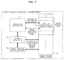
- FIG. 3 depicts an illustrative target computer 300 on which the translated applications execute as shown in FIG. 7 (and also, as described below, in FIG. 8).
- Target computer 300 is illustratively a graphics workstation.
- the two computers not surprisingly, contain many similar components which, again, bear reference numerals having the same last two digits. Also again, however, there are some differences.
- target computer 300 like translating computer 200, does not include a floppy disk unit. Its connection to the outside world is made by way of a local area network (LAN) by way of LAN controller 328.
- LAN local area network
- ROM 335 does not include a complete BIOS but, rather, only a boot loader 3351, as described above.
- FIG. 3 further shows those files in hard disk 333 of the target computer which are particularly relevant to the run-time portion of the translation process as depicted in FIG. 7.
- hard disk 333 stores the two translated applications 3332 and 3333 output by translating computer 200--corresponding to translated applications 2335 and 2336 of FIG. 2, translated application 63 of FIG. 6, and translated application 71 of FIG. 7.
- Also illustratively stored on hard disk 333 are two applications 3334 and 3335 which have been compiled for execution on target machine 300.
- FIG. 8 depicts an alternative translation arrangement.
- the translated source machine application program 81 accesses an image 84 of the source machine address space.
- the system software which serves the translated application instead of being a simulation, is, at least in part, a translation 87 of at least portions of the source machine system software.
- this translation of the source machine system software is created by subjecting the source machine system software to the very same translation processing as the application, i.e., the processing shown in FIG. 6.
- Translated system software 87 is stored as a library in target machine 300 (FIG. 3), where it bears the reference numeral 3336. As described in further detail hereinbelow with reference to FIG. 23, the translated application is linked to the translated system software prior to their being loaded for execution into RAM 334 of target machine 300. Thus when translated application 81 requests at least particular system services, it is the translated version of the source machine system software program implementing those services that is executed on the target machine, rather than a mere simulation, i.e., functionally rewritten version, thereof.
- Translated system software 87 operates on the image of the source machine address space exactly as it did in the source machine. The semantics of the source machine system software are thus preserved identically. This provides significant advantages over the prior art approach of simulating, i.e., rewriting, the source machine system software.
- addresses referenced by translated system software 87 are within image 84. That is, they are addresses of memory locations and devices in the source machine. The above-consideration relative to rogue programs is thus applicable to translated system software 87.
- the fact that the address space of the source and target machines are, invariably, different is not a problem to the extent that the addresses that are referenced correspond to non-device-related, or ordinary RAM, locations in both machines, because ordinary RAM locations are indistinguishable from one another.
- attempted accesses to locations associated with particular hardware devices for example, will not, in general, be properly carried out.
- a virtual hardware environment is provided in the target machine to deal with the foregoing.
- a component of the translation software--virtual hardware event monitor 89-- is periodically invoked on a frequent basis, e.g., every 0.01 second, in response to a timer interrupt.
- monitor 89 checks the status of all the locations in image 84 that correspond to source machine hardware devices and, if changes since the last check have occurred, it carries out the intended access in the target machine address space either directly or via target machine system software 88.
- monitor 89 also monitors those locations in the target machine address space corresponding to target machine hardware and updates any corresponding locations in image 84 so that any changes in the state of the target machine hardware will be made known to the translated application 81 and the translated system software 87.
- translated system software 87 to serve translated application 81 in the identical manner as the application is served in the source machine relies on the ability of the designer of event monitor 89, in conjunction with the target machine system software 88, to exactly simulate the operation of the source machine hardware.
- problems outlined above relative to the inadequacy of the documentation typically available for the source machine system software do not arise in the context of simulating its hardware. The reason is that the interfaces to the various hardware elements are well-defined and, indeed, the documentation available to the designer of event monitor 89 is the same as that available to, and relied upon, by the source computer hardware designer, this being the documentation supplied by the various manufacturers of the various hardware components.
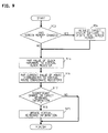
- FIG. 9 is a flowchart of the operation of virtual hardware event monitor 89.
- monitor 89 begins at step 902 by determining whether the executing translated (application or system) software has made a screen change--by writing to the screen memory within image 84--since the last invocation of the monitor. This test can be performed in any of a number of ways, depending on the capabilities of the target machine. If there has been a change, monitor 89 invokes a service of target machine system software 88 to update, in the actual screen memory of the target machine, the values of the pixels that have changed.
- Monitor 89 then proceeds to step 914, at which it copies the current value stored in the target machine clock register into the virtual clock register, i.e., the location within image 84 that corresponds to the source machine clock register. Similarly, at step 916, it copies the current values stored in the locations within the target machine at which the mouse coordinates are stored into the analogous locations within image 84.
- monitor 89 checks a queue maintained by the target machine system software in which keyboard events are placed. If it finds that there has been a change since the last time this queue was checked, processing proceeds to step 923 at which this information is made known to the executing translated application. Illustratively, this is accomplished by simply placing the keyboard event information directly into a similar queue maintained within image 84. Alternatively, an interrupt procedure within the translated source machine system software could be invoked by monitor 89 to put the information into that queue.
- monitor 89 exits, to be re-invoked later.
- FIG. 10 is a flowchart depicting an illustrative order of events for performing translation from the development of the translation software to the execution of translated software.
- the first steps are to create a translator and virtual hardware event monitor. This is, of course, principally a computer programming task.
- the translator and event monitor it is possible to proceed and a) translate all or part of the source machine system software and store it in the target machine, as indicated at 1006,1008 and 1011; b) implement any desired system simulation software and store it in the target machine, as indicated at 1012 and 1013; and c) translate one or more applications, bind them to the translated and any other system software, and also store them in the target machine, as indicated at 1014,1016,1019,1020 and 1022. If, as determined at step 1024, it is desired to execute a particular one of the translated applications on the target machine, the application can be directly executed as indicated at 1028.
- step 1028 is illustratively carried out by an application start-up procedure within target machine system software 88.
- This procedure serves the functions of invoking a target machine system service that will allocate memory space for image 84; loading translated application 81 into its proper place within the image, starting up monitor 89, essentially by instructing it to set up the aforementioned timer interrupt; and then passing control to application 81.
- the application start-up procedure functions to deactivate monitor 89, essentially by instructing it to de-activate its timer interrupt; release the memory space allocated for image 84; and return program control to target machine operating system 88.
- the principal advantage of translation over software emulation is the fact that the time that would otherwise be consumed in decoding and mapping is eliminated, resulting in a significant performance improvement--typically about 3 to 1.
- the translated software typically requires vast amounts of storage space--typically a 15-to-25-fold increase over the original program code--due to the above-mentioned expansion of program code that results from the need to replicate explicitly the primary and side effects of the source machine instruction set.
- An example of how source machine code expands when the side effects are made explicit is shown in the first two columns of FIG. 11. This expansion of the program code, and its attendant requirement of large amounts of storage and slower execution, has, to this point, rendered object code translation an essentially unused alternative.
- FIG. 12 presents an overview of the processing performed by the translator to carry out the translation.
- the translation process is similar in many respects to a conventional compiler process and, as such, has three principal components: parsing, transformation and code generation.
- the parsing component reads the input application software or system software object code and converts it into an intermediate language representation suitable for further, machine-independent processing.
- the transformation component then reduces the size of the intermediate language code by eliminating redundancies and unnecessary code.
- the code generation component converts the intermediate language representation to the object language of the target machine.
- the parsing component has three phases: disassembly, analysis and mapping.
- Disassembly involves the straightforward decoding of an individual instruction of the object code and conversion thereof to assembly language form, both the decoding and conversion being carried out in accordance with known, conventional techniques.
- the analysis phase is responsible for managing the disassembly process.
- the initial task of the disassembly/analysis is to create an assembly language representation of the input program divided into so-called basic blocks.
- a basic block is a sequence of instructions that has exactly one instruction at which control can enter the sequence during execution and exactly one instruction at which control leaves the sequence during execution.
- each basic block is annotated with comment lines identifying a) an arbitrarily selected name for the basic block, b) the beginning of the basic block, c) the end of the basic block, and d) the so-called "successors" of the basic block, these being basic blocks to which flow of control can be directly passed.
- a single comment line is illustratively used to effect both a) and b).
- a number of skeleton basic blocks annotated as just described, and grouped into so-called “procedures” as discussed more fully below, are shown in FIG. 15.
- the process of identifying the basic blocks is carried out by creating a so-called segment list, which contains the starting and ending locations of segments of the program which are identified as being either code or data.
- segment list initially contains a single entry, which contains the starting and ending locations of the entire program, denoted as "A" and "Z", respectively.
- FIG. 13 is a flowchart of the entire parsing component of the translator, with the majority of that flowchart being directed to the identification of code and data segments and thus, ultimately, of the basic blocks. Indeed, as will be appreciated after FIG. 13 is fully described, step 1311 carries out the disassembly; step 1335, the mapping; and the remaining steps, the analysis.
- the processing begins at step 1301 by fetching an entry from a so-called exploration list which is a list of known basic block starting points.
- the exploration list is a list of addresses of entry points for the object code program, i.e., locations in the object program that may receive control when execution of the program begins.
- an application has only one entry point.
- system software which may be also translated, typically has many entry points, i.e., all of the various locations where an application might call it.
- the initial exploration list is denoted at 1401 in FIG. 14 and in this case contains a single entry, viz., the location of the program entry point denoted "E".
- E the location of the program entry point
- step 1303 If, as determined at step 1303, the exploration list is empty, processing to identify the code and data segment blocks is complete. Otherwise, a further test is made at step 1307 to determine whether the instruction at the address under consideration has, indeed, already been encountered, the possibility of this occurring being explained at a more opportune point hereinbelow.
- the instruction under consideration has not been previously encountered, it is, by definition, the first instruction of a newly-identified basic block and its address is saved for later use. Initially, then, it is location "E" that is so saved.
- step 1311 the instruction is disassembled so that the subsequent step, 1313, can determine whether the instruction changes the flow of control, i.e, is a branch, call or return. If it does not, the end of the segment has not yet been found.
- the address is incremented at step 1315 and steps 1311 and 1313 are repeated for the next instruction.
- Step 1317 adds the addresses of the instructions to which the current instruction may transfer control to the exploration list since each such address is, by definition, the first instruction of a respective basic block.
- locations "G" and "K” are instructions to which flow of control can pass from the branch instruction at location "F”.
- Step 1319 uses the address saved at step 1309 and the current address to create a new code segment entry in the segment list.
- the segment list now contains three entries, tentative data segments at locations "A-E” and "F-Z" and a code segment at locations "E-F".
- processing returns to step 1301 to process another entry from the exploration list, now the entry "G".
- the same processing steps will be followed in this case, resulting in the identification of another code segment at locations "G-H” and the adding to the exploration list of location "M", the instruction at that location being a target of the instruction at location "H".
- Step 1308 determines whether the current instruction is the first instruction of an already-identified segment. This would occur if location "K" had been previously placed on the exploration list as the result of it being the target of an instruction that was encountered prior to the instruction at location "H". In that case, nothing more would need be done, and processing would again return to step 1301. In this case, however, location "K” has not yet been identified as the first instruction of an already-identified segment. Accordingly, a new segment at locations "K-F" is split off at step 1310 and processing again returns to step 1301.
- step 1303 it will be discovered at step 1303 that the exploration list is empty. Any segments not identified as code by this point in the processing are data, i.e., non-instructions, because no path in the flow of control was discovered by which such instructions could be possibly reached for execution. At this point, moreover, all code segments are, by virtue of the methodology employed, guaranteed to be basic blocks.
- step 1331 the aforementioned successors of the basic blocks are identified.
- This is readily accomplished by simply examining the last instruction of each basic block and determining the basic blocks to which flow of control can pass. So-called procedures of the original program are then identified at step 1333. This is achieved by first identifying individual ones of the basic blocks as being so-called “procedure head blocks", this being a basic block whose first instruction is either a) an entry point (as described above) or b) the target of a call instruction.
- a procedure is comprised of all blocks reachable (through a sequence of successors) from a so-called procedure head block a) which are not themselves procedure head blocks and b) to which flow of control does not pass through any intermediate procedure head block.
- FIG. 15 shows a plurality of basic blocks 1501 through 1505.
- each basic block has a comment line of the form "#BLOCK block150x” denoting both the beginning of the basic block and its name; a comment line of the form “#ENDBLOCK block150x” denoting the end of the basic block and, again, its name; a comment line of the form "#SUCCESSORS 150a, 150b, etc” denoting the successors of the basic block; and, of course, the program code. Only the instructions which alter flow of control are explicitly shown (in program pseudo-code) in the FIG.
- basic block is a procedure head block. All of the remaining basic blocks are reachable from block 1501.
- basic blocks 1502 and 1503 are reached via a conditional branch to LABEL1. If the branch is taken, flow of control passes to LABEL1, which marks the first instruction of basic block 1503. Otherwise, control "falls through” the branch to the first instruction of basic block 1502.
- Block 1504 is reached by a call to LABEL2 from basic block 1503, that label marking the first instruction of basic block 1504.
- basic block 1505 is reached both by a fall-through from basic block 1504 and from itself via the conditional branch to LABEL3.
- Successors 1502 and 1503 are part of the procedure headed by basic block 1501.
- basic blocks 1504 and 1505, although they are also successors to basic block 1501 belong to another procedure.
- basic block 1504 qualifies as a procedure head block in its own right since it is the target of a call.
- flow of control to basic block 1505 from basic block 1501 passes through an intermediate procedure head block, viz., basic block 1504.
- basic block 1505 is not in the procedure headed by basic block 1501. Rather, it is only in the procedure headed by basic block 1504.
- Step 1333 of FIG. 13 completes the analysis phase of the parsing component.
- the last parsing step--mapping-- is then performed at step 1335. This is the process of substituting, for each disassembled instruction, an equivalent sequence of operations--including the side effects--expressed in terms of a machine-independent intermediate language.
- the mapping process performed at step 1335 is thus quite similar to the mapping performed during conventional software emulation, as described above.
- an instruction set is the ensemble of all instructions that are available to the programmer of a computer.
- Each instruction has a syntax, which defines the form of the instruction, and semantics, which are the operations which are performed upon the execution of the instruction.
- the semantics include both primary and side effects.
- the primary effect may generate a data value, which may be thought of as "primary information".
- the primary effect of an ADD instruction is the addition of two quantities.
- the primary effect may be a non-data operation, for example, a change in the flow of control, as in a JUMP.
- a side effect is any effect of an instruction that is a) other than its primary effect and b) is potentially useful at a later point in the program execution.
- a side effect may, for example, generate various pieces of "secondary" information.
- side effects of arithmetic instructions often include the setting of condition code bits, the values of those bits being indicative of properties of either the arithmetic result (such as whether that result is zero or non-zero) or of the operation itself (such as whether the result overflowed).
- a side effect may relate not to the generation of secondary information, but rather to specifics of the semantics of an instruction. An example is whether the high-order half-word of a word-length register is or is not preserved when a half-word operation is performed on the register.
- a particular side effect may or may not have been intended by the processor design team. For example, it may turn out that, due to an error in the processor firmware, a particular condition code bit that is supposed to always be reset upon the execution of a particular instruction may be left un-reset when that instruction is executed with particular operand values.
- An example of the case where a particular non-subtle side-effect is used for other than its originally intended purpose is the setting of the carry condition code bit upon exit of a system call as a way of reporting back to the calling program that the system call failed.
- An example of a subtle side effect that may be used to advantage might be the fact that, when a half-word operation is performed on a word-length register, the high-order half-word of the register is preserved. This being so, a program may rely on this effect to pass data to subsequently executed portions of the program. In effect, the high-order half-word of the register functions as an extra half-word register.
- the mapping process must replicate all such side effects faithfully because the creator of the program being translated may have indeed relied on them in unforeseeable ways.
- each instruction of the source machine instruction set is analyzed to appreciate both its primary effect and all of its side effects.
- the processor reference manual or other documentation can be used to gather information about the side effects.
- a skeleton intermediate language code sequence can then be developed for each source machine instruction. This sequence includes intermediate language instructions which perform the primary effect of the instruction and the known side effects.
- the skeleton for an ADD instruction will include individual intermediate language statements which calculate and set the various condition code bits. (Although both the source and target machines may have nominally similar side effects, the detailed semantics of the side effects may be different.
- the MOVE instruction on one machine may set the zero and negative condition code bits while the equivalent instruction on the other machine may not affect the condition code bits at all.
- the skeleton sequence will explicitly replicate the source machine side effects rather than relying on the corresponding target machine side effects.
- mapping then consists of adding to the intermediate language code listing already created a) code for fetching the operands of each instruction, b) the appropriate skeleton and c) code for storing the result of the instruction if necessary.
- disassembly and mapping phases are source machine-dependent.
- a different disassembler and mapper must be created for each different source machine. This can be facilitated by reference to the manufacturer's instruction set manual.
- the analysis is machine-independent since its function is essentially one of managing the disassembly.
- the principal function of the optimization phase is, as mentioned above, to analyze the expanded program code and eliminate instructions that are, in fact, unnecessary for proper program functionality.
- the analysis and instruction elimination are carried out globally. That is, the necessity or non-necessity of retaining or eliminating a particular instruction is determined on the basis of an examination of the entire program being translated (as opposed, for example, to only a basic flow block or procedure).
- This approach maximizes the amount of program code that can be identified as being, in fact, unnecessary. (Indeed, this is important because the expanded code is so voluminous that it is advantageous to exploit every opportunity to reduce its size.)
- Known optimization techniques--initially developed for compilers--are illustratively used to carry out this operation.
- optimization techniques can actually improve the quality of the program by, for example, deleting artifacts that may have been created in a given application by the source machine compiler if that compiler did not, in fact, embody such optimization techniques.
- artifacts may include, for example, unreachable code and unnecessary loads from, and stores to, memory.
- the input to the optimization phase is the intermediate language representation of the source application annotated, as in FIG. 15, with all side-effects made explicit
- a small section of actual such program code is shown in the middle column of FIG. 11.
- the object of the data flow analysis is to classify all mentions of variables in the intermediate language instructions as being either "definitions" or "uses".
- a "variable” is the name of a register (including condition code bits), memory location or stack location.
- a “definition” is an occurrence of a variable in an instruction in which the variable gets a new value.
- a "use” is any other occurrence of the variable, i.e., a place where the defined value is used.
- Each use is a mention of a value created by some definition (or set of definitions) and, by examining the possible flow of control paths through a procedure the set of definitions which could generate the value in a particular use are deduced.
- the process of associating definitions with uses is, in fact, the aforementioned definition-use chaining and the information thus generated is referred to herein as "the data flow results".
- the data flow results are thereupon used to perform a number of developed-for-compilers transformations, illustratively including "common sub-expression elimination”, “invariant code motion”, “constant propagation”, “scalar propagation” and “dead code elimination”.
- Dead code elimination which is the last of the transformations to be performed, involves the removal of instructions involving definitions which have no uses. It is the most effective of the transformations (in terms of the number of instructions that can be eliminated during a translation optimization) because the expanded intermediate language version is replete with instructions devoted to the calculation of side effects which are never used. This is illustrated in FIG. 11 which shows, in three columns, how five lines of source machine program code are expanded to thirty-nine lines of intermediate language code and, after dead code elimination, is reduced to ten lines of translated code.
- Common sub-expression elimination involves the removal of redundant calculations of the same value.
- a common sub-expression is identified by determining that a given pair of definitions is calculated by performing the same operations on the same variables, provided that the variables in each calculation have the same associated definitions as the corresponding variables in the other calculation.
- register X is assigned the results of adding registers A and B
- later register Y is also assigned the results of adding registers A and B, and assume there are no intervening assignments of registers A or B. It is not optimal to perform this addition twice. Accordingly, a variable @1 is created to hold the results of the addition of variables A and B. That addition is then replaced in the assignments to variables X and Y by a reference to variable @1.
- Invariant code motion involves the case where the calculation of a value is performed within a loop in the flow of control. If the uses involved in the calculation only have associated definitions which are outside the loop, the calculation will be invariant within the loop. That is, the same value will be calculated in every iteration of the loop. Accordingly, the calculation can be moved ahead of the loop so that it is only performed once and execution time (although not code size) is improved.
- Register X is assigned the result of adding registers A and B within the loop defined by LABEL. Assume, however, that there are no assignments to registers A or B within the loop, i.e., the uses of registers A and B in the calculation have no associated definitions within the loop.
- Constant propagation involves replacing a use with a constant if the use has only one associated definition and that definition, in turn, is an assignment of a constant to a variable.
- the reference to register A in the second instruction is replaced by the value "1" itself.
- the data flow results are thereupon updated to remove the association between the use and definition in question.
- the subsequent dead code elimination transformation finding no uses for the definition, will delete it as superfluous.
- Scalar propagation is similar to constant propagation in that the use, again, has only one associated definition.
- the definition constitutes the assignment of the value of a first variable (instead of a constant) to a second variable.
- the use of the second variable can be replaced with a reference to the first as long as there is no intervening re-definition of the first variable.
- the data flow results are thereupon appropriately updated.
- the reference to register A in the second instruction is replaced by a reference to the contents of register B (as long as there is no intervening assignment to register B).
- the data flow results are updated, this time to remove the association between the use of register A and the definition in question (and, in order to keep the data flow results accurate, to add an association between the new use of register B and the definition associated with that use).
- the original definition may or may not become superfluous, depending on whether that definition has at least one other use for which there is, indeed, an intervening assignment. If there are none, that definition will be deleted by the (subsequent) dead code elimination.
- the transformation component of the optimization phase processes the source application on a procedure-by-procedure basis.
- the reason for this is that the data-flow analysis techniques used for optimization have explosive growth in execution time and space as the size of the program unit being optimized increases. By limiting optimization to procedure-sized units, the growth problem can be kept to a manageable level. This approach means, however, that special account must be taken of the presence of calls within a procedure to other procedures. The reason is that definitions made in a first procedure may have uses in a second procedure called thereby and vice versa, and the definition-use chaining process must take account of this or the overall translation process will produce incorrect code.
- One method for ensuring correctness in this regard is to blindly assume that every variable is both used and defined within every procedure call.
- the blind assumption that every definition is used in the called procedure will ensure that the definition in question is not removed during dead code elimination.
- a definition in the calling procedure is the assignment of a constant value to a register and the contents of that register are used in the calling procedure after a call.
- the called procedure redefines the contents of the register.
- a more efficacious approach is to use a so-called call tree to guide the optimization process.
- a call tree in particular, is a static reflection of the procedure-calling behavior of the program.
- the procedures at the entry points of the program are the "roots" of the tree. (Normally an application has only one entry point and thus there is only one root, as would be intuitively expected.)
- Each procedure called by the root is a "branch” of the tree; each procedure called by a branch is a "sub-branch” of that branch; and so forth.
- Procedures which call no other procedures are called “leaves”.
- the set of procedures that can be reached by one or more calls from a given procedure are its "descendants" and it, conversely, is their "ancestor".
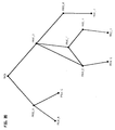
- FIG. 20 shows an illustrative call tree which has a procedure known as "MAIN" as its root and a number of procedures known as PROC_A, PROC_B,...PROC_K as its descendants.
- MAIN calls PROC_A which, in turn, calls PROC_B and PROC_C.
- PROC_D calls PROC_F which, in turn, calls PROC_E. The latter, recursively, calls PROC_D.
- the data flow analysis step processes all procedures twice--the first time in "forward" call tree order, i.e., from root to leaves, and the second time in "reverse” call tree order, i.e., from leaves to root.
- an illustrative order of processing in the first pass is MAIN, PROC_A, PROC_B, PROC_C, PROC_D, PROC_F, PROC_E, PROC_H, PROC_G, PROC_I, PROC_K and PROC_J.
- An illustrative order of processing in the second pass is PROC_B, PROC_C, PROC_A, PROC_G, PROC_I, PROC_H, PROC_E, PROC_F, PROC_J, PROC_K, PROC_D and MAIN. Note that the recursive arc from PROC_E to PROC_D is ignored in establishing these orderings. Indeed, when performing data flow analysis for portions of the call tree which are involved in such recursive cycles, the definition-use chaining, with respect to calls, may become extremely complicated. For this reason, the above-mentioned pessimistic assumption that every variable is both used and defined within every called procedure is typically used for such portions of the call tree. Thus the portion of the call tree in FIG.
- PROC_D which includes PROC_D, PROC_F and PROC_E and their calls to one another are treated in this fashion.
- the first data flow analysis pass is directed to the creation of a list of those variables used in a procedure that a) are at least potentially defined by a procedure called thereby and b) are used, after the call, in the calling procedure.
- This list is used as a first approximation of a list of variables whose definitions in the called procedure must be preserved for the benefit of the calling procedure which uses them.
- This approximation will be later refined in the second pass to include only those definitions that actually do occur in the called procedure. (For call tree leaves, this refinement could be done in the first pass but, in this embodiment, is not.)
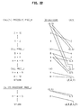
- FIG. 21 shows a skeleton of two of the procedures shown in the call tree of FIG. 20--PROC_K and PROC_J, the latter being called twice in the course of the former.
- the net effect of the first-pass data flow analysis of PROC_K vis-a-vis the list for PROC_J will be to find that variables A,B,R,X and Y--whose appearances in the various procedures are described below--all meet the above criteria. That is, they are potentially defined by PROC_J and are used after to a call thereto.
- the subsequent second-pass data flow analysis of PROC_J will refine this list to the single variable X, which is the only variable on the list actually defined in PROC_J.
- the first step of data flow analysis is to find every explicit mention of a variable and classify each one as being either the location of a definition or the location of a use. This is reflected in FIG. 21 in the two columns which list the definitions and uses present at each program instruction. These definitions and uses are termed "explicit" definitions and uses and, as seen in the FIG., A, B, X, Y and Z are all both defined and used in PROC_K.
- the second step of data flow analysis is to initially classify every call as being the location of a definition of all variables which have uses in the procedure. These are termed implicit definitions and are shown in parentheses in the "definitions" column across from each of the calls to PROC_J. Since A, B, R, W, X, Y, and Z all have uses in PROC_K, each CALL PROC_J instruction is initially regarded as the location of an implicit definition of each of those variables. This initial classification embodies the above-mentioned pessimistic assumption about definitions within calls; at this point it must be assumed that each call defines every variable mentioned in the calling procedure.
- the next step is to perform the definition-use chaining in order to associate each use with one or more definitions.
- the association of particular uses with particular definitions is shown in FIG. 21 by lines which connect each use with its apparent definition.
- each call is examined and the definitions ascribed thereto that have associated uses are added to a list of implicit uses associated with the return instruction of the procedure being called.
- variables A, B, R, X, and Y are recorded at the RETURN instruction of PROC_J. This represents the best guess from the standpoint of PROC_K as to the identity of those variables that may be defined by PROC_J. Note that since W and Z have no explicit uses after any call to PROC_J--at least not without an intervening definition--they are not included in the list of implicit uses associated with the RETURN at the end of PROC_J.
- variable R which has only implicit definitions and uses in PROC_K, is still included in the list. This is, indeed, appropriate because, as discussed above, variable R is used by some procedure which calls PROC_K and, at this point, it must be assumed that that variable may be defined in PROC_J. (Because PROC_J has not been examined yet, the definitive answer is not yet known.)
- PROC_J is a call tree leaf, it contains no calls and since the first pass is, in fact, directed to gathering information about calls, there is no need to process PROC_J or any other of the leaves in the first pass.
- the second, reverse pass through the call tree by the data analysis step performs the data flow analysis of each procedure all over again but now makes use of the information gathered in the first pass, as just described. Specifically, the definition-use chaining is again performed--from scratch--but it now incorporates the refined list of implicit definitions and uses developed for each procedure.
- PROC_J is processed before PROC_K, and the results of the processing are illustrated in FIG. 22.
- the first step of the second pass data flow analysis of PROC_J is, again, to find every explicit mention of a variable and classify it as being either the location of a definition or the location of a use. Included in the "uses" column is the list of implicit uses developed during the first pass, that list having variables A, B, R, X and Y.
- this pass includes the step of creating a list of implicit definitions associated with the entry point of the procedure, that list including those variables used in the procedure but not defined therein.
- that list is comprised of the variables Q and S.
- next data flow analysis step involves associating implicit definitions with all procedures that are called by the procedure being analyzed.
- PROC_J does not call any other procedures and therefore no action is taken at this step.
- the explicit uses of variables Q and S are associated with the implicit definitions associated with the entry point of PROC_J.
- variables A, B, R and Y have no definitions in PROC_J despite the fact that they were included in the list of variables that, from the vantage point of PROC_K, were potentially defined in PROC_J.
- the first pass list can be refined by discarding those variables (as shown in FIG. 22 by slashes placed through them), thereby leaving variable X as the only entry.
- variable X is the only variable defined in PROC_J which is used in PROC_K subsequent to a call to PROC_J.
- PROC_K unlike PROC_J, does contain calls.
- definitions need to be associated with these calls.
- a list of implicit uses is associated with each procedure call, that list being the list of implicit definitions previously developed during the second pass for the called procedure.
- PROC_K the list of variables Q and S developed as implicit definitions at the entry point of PROC_J are used as implicit uses for PROC_J calls in PROC_K.
- This step is necessary because definitions of variables Q and S in PROC_K--or in procedures which call it--are needed by PROC_J.
- variables Q and S are, in fact, not defined in PROC_K and are, therefore, provided in the implicit definitions list associated with the entry point of that procedure in precisely the same way as they were for PROC_J.
- variable R is no longer assumed to be defined by the PROC_J calls, the implicit use thereof at the exit of PROC_K now no longer has an associated definition and the list of implicit uses can be refined to exclude that variable (as shown in FIG. 22 by the slash placed through the "R").
- variable R In direct analogy to the case of variables A and B just discussed, the elimination of variable R from the implicit use list at the exit of PROC_K will subsequently assist in the optimization of procedures which call PROC_K because variable R will no longer appear on the list of variables that are assumed by those calling procedures to be defined in PROC_K.
- PROC_K The second pass of data flow analysis through PROC_K is also now complete.
- the subsequent transformations of common sub-expression elimination, invariant code motion, constant propagation, scalar propagation and dead code elimination are then performed on PROC_K and the optimization of the procedure is complete.
- the last phase of the transformation component of the optimization is "synthesis".
- the overall goal of the synthesis phase of transformation is to produce a representation of the program that is closer to the original compiler source language than is the assembly language representation currently being operated on. Doing this will provide the code generation component (discussed below) with greater opportunity to use the resources and capabilities of the target machine effectively. This improves the translated program both in terms of its size and speed of execution (performance).
- the synthesis phase of transformation looks for sequences of intermediate language instructions that are recognizable as "higher level" functions that can be more efficiently represented than they are in the now-converted-to-intermediate-language source machine object code.
- the source machine processor is not capable of performing a 32-bit multiply operation directly but, rather, requires a series of instructions to carry it out.
- the target machine may, however, be capable of performing a 32-bit multiply directly.
- the synthesis phase can be designed to recognize the pattern of instructions as, indeed, constituting a 32-bit multiply and to substitute an appropriate single instruction in the intermediate language version.
- Other examples are sequences resulting from C language "switch” statements, Pascal "case” statements, looping constructs, etc.
- the repertoire of recognizable sequences available to the synthesis phase is developed empirically during the development of the translation software by examining the facilities of the source and target machines and the characteristics of the original object code (which are, of course, dependent on the characteristics of the compiler which generated the source machine application object code in the first place).
- the code generation phase of the translation process is virtually the same as the code generation phase of a conventional compiler. That is, the intermediate language version of the application, optimized as described above, is converted to the assembly language of the target machine by substituting one or more appropriate target machine assembly language instructions for each intermediate language instruction. The resulting code is thereupon assembled into target machine object code and bound with the translated system software.
- FIG. 23 shows an illustrative way in which a translated application is bound to the translated system software and target machine system software.
- binding refers to the process by which symbolic addresses in software are converted, ultimately, to actual addresses that the processor can operate on.
- the binding is illustratively in two stages.
- first stage known as "linking”
- symbolic references within a first object code module (such as a translated application) to an entry point of a second object code module (such as the translated system software) are converted into numerical offsets which label all such entry points relative to the first address of the combined object programs.
- second stage which is encompassed within the so-called “loading” process, those offsets are thereafter converted into addresses that the processor can operate on.
- the first column shows three object modules--a translated application, translated system software and target machine system software--in their as-compiled form.
- each of the modules may be thought of as having its own set of address locations beginning at 0x0 and ending at 0x1000, 0x200 and 0x600, respectively.
- the translated application illustratively includes a call to a procedure PROC_J which is internal to the application.
- the code generation component of the translator--which provides a compiler function in this regard-- has been able to recognize the reference to PROC_J at 0x200 and has replaced what had been a mention of "PROC_J" in the intermediate language code with an offset indicative of the location of the entry point of PROC_J relative to the starting point of the module--that entry point illustratively being 0x800.
- the translated application further includes two calls to system services--SERVICE1 and SERVICE2--which are programs within the translated system software and target machine system software, respectively. Since these calls reference programs that are outside of the translated application, the mentions of SERVICE1 and SERVICE2 cannot be "resolved", i.e., replaced with offsets, by the code generator. Similarly, a reference within the translated system software to a system service SERVICE3 within the target machine system software remains unresolved at this point.
- the second column of FIG. 23 shows the three modules after linking. Specifically, the linker has combined the three modules into a single address spectrum from 0x0 to 0x1800 and each instruction has an address within that spectrum. Thus, the first address of the translated system software is now 0x1000 while the first address of the target machine system software is 0x1200.
- the various symbolic references to SERVICE1, SERVICE2 and SERVICE3 can now been replaced with offsets--0x1000, 0x1300 and 0x1600, respectively, reckoned relative to the starting point of the linked modules.
- the offsets provided by the linker provide an adequate basis for program execution; the actual address in memory of program code identified by an offset in, say, a call instruction is determined during actual program execution by adding the offset to the address of the call instruction itself.
- offset 0x800 in the second translated application call can be added to the location, 0x200, of the call itself in order to determine that flow of control should pass to location 0x1000.
- the processor requires the executable code to contain the addresses rather than offsets. This is accommodated when the code is loaded into RAM for execution by simply adding to each offset the actual starting RAM address at which the code is loaded.
- the linked modules have been loaded into RAM beginning at location 0x5000, and all calls now identify as the target of the call the pre-computed address given by the sum of 0x5000 with the relevant offset
- the source machine and the target machine have disparate processors having disparate instruction sets.
- the two processors belong to a common processor family--and thus may have the same instruction sets--but one of the processors has, for example, a 24-bit address space and the other has a 32-bit address space.
- the translation may involve only minor conversions of the instructions.
- the application executing on the target machine and invoking translated system software need not itself be a program that was translated.
- the source and target machines may use the identical processor type and thus an application compiled for the source machine will be executable on the target machine without having to be translated.
- the system software and/or the address spaces of the two machines may be different. It may thus be advantageous to link the not-needed-to-be-translated application with the translated system software for execution in the target machine.
- the input program could be, alternatively, for example, a) an assembly language version thereof or b) embodied in so-called interpretive code which is in a form intended to be interpreted on the source machine.
- interpretive code is in a form intended to be interpreted on the source machine.
- An example of the latter are programs output by the UCSD Pascal P-code compilers.
- the use of a different, intermediate assembly language may not be necessary. Rather, then expansion can be carried out in terms of the original assembly language or other instruction set.
Claims (12)
- Appareil d'exécution de programmes d'application (1332, 1333...1339), normalement exécutables sur un système informatique source (100), sur un système informatique cible différent (300), les programmes d'application (1332, 1333...1339) n'étant pas normalement exécutables sur le système informatique cible (300), caractérisé par un corps de logiciel de système (3331, 3336) pour fournir des services de système à un programme d'application traduit (3332, 3333) quand le programme d'application traduit (3332, 3333) est exécuté sur le système informatique cible (300), le corps de logiciel de système (3331, 3336) comportant au moins des parties de logiciel de système informatique source (1331), non normalement exécutables par le système informatique cible (300), traduites en une forme (3336) exécutable sur le système informatique cible (300) sans autre traduction, simulation ou émulation requise durant l'exécution du logiciel de système informatique source traduit (3336) sur le système informatique cible (300).
- Appareil selon la revendication 1, dans lequel ledit logiciel de système est adapté pour créer une image (84) de l'espace adresses dudit système informatique source (100) à l'intérieur d'un espace mémoire dudit système informatique cible, et ledit appareil comprend un moyen de contrôle d'événements (89) pour contrôler des emplacements prédéterminés à l'intérieur de ladite image et fonctionnant en réponse à des changements du contenu desdits emplacements pour effectuer des changements du contenu dans des emplacements correspondants de l'espace adresses dudit système informatique cible en dehors de ladite image.
- Appareil selon la revendication 1, dans lequel ledit logiciel de système (87) est adapté pour créer une image (84) de l'espace adresses dudit système informatique source (100) à l'intérieur d'un espace mémoire dudit système informatique cible (300), et ledit appareil comprend un moyen (89) pour contrôler des emplacements prédéterminés à l'intérieur de l'espace adresses dudit système informatique cible (300) en dehors de ladite image (84) et fonctionnant en réponse à des changements du contenu desdits emplacements pour effectuer des changements dans des emplacements correspondants à l'intérieur de ladite image (84).
- Appareil selon la revendication 1, dans lequel ledit logiciel de système (87) est adapté pour créer une image (84) de l'espace adresses dudit système informatique source (100) à l'intérieur d'un espace mémoire dudit système informatique cible (300), et ledit appareil comprend un moyen (89) pour contrôler des emplacements à l'intérieur de ladite image (84) qui correspondent à des dispositifs matériels dans ledit système informatique source (100) et fonctionnant en réponse à des changements du contenu desdits emplacements pour effectuer des changements dans des emplacements de l'espace adresses dudit système informatique cible (300) qui correspondent à des dispositifs matériels dudit système informatique cible (300).
- Appareil selon la revendication 1, dans lequel ledit logiciel de système (87) est adapté pour créer une image (84) de l'espace adresses dudit système informatique source (100) à l'intérieur d'un espace mémoire dudit système informatique cible (300), et ledit appareil comprend un moyen (89) pour contrôler des emplacements prédéterminés dans l'espace adresses dudit système informatique cible (300) associé à des dispositifs matériels particuliers ledit système informatique cible (300) et fonctionnant en réponse à des changements du contenu desdits emplacements pour accéder à des emplacements dans lesdites images (84) associés à des dispositifs matériels respectifs dans ledit système informatique source (100).
- Appareil selon la revendication 2 ou 5, dans lequel le fonctionnement dudit moyen de contrôle d'événements (89) est sollicité périodiquement dans ledit système informatique cible (300).
- Appareil selon la revendication 2 ou 5, dans lequel le fonctionnement dudit moyen de contrôle d'événements (89) est sollicité périodiquement dans ledit système informatique cible (300) en réponse à une interruption d'horloge.
- Méthode d'exécution, sur un système informatique cible (300), d'un logiciel d'application (1332, 1333...1339) exécutable sur un système informatique source (100), mais pas sur le système informatique cible (300), caractérisée par les étapes de: liaison (1020) du logiciel d'application traduit (3332, 3333) à un corps de logiciel de système traduit (3336) qui est référencé au logiciel d'application traduit (3332, 3333), le corps de logiciel de système (3336) étant adapté pour fournir des services de système au logiciel d'application traduit (3332, 3333) quand le programme d'application traduit (3332, 3333) est exécuté sur le système informatique cible (300), le corps de logiciel de système (3331, 3336) comportant au moins des parties de logiciel de système informatique source (1331) non normalement exécutables par le système informatique cible (300) traduites en une forme (3336) exécutable sur le système informatique cible (300) sans autre traduction, simulation ou émulation requise durant l'exécution du logiciel de système informatique source traduit (3336) sur le système informatique cible (300); et l'exécution du logiciel d'application et du logiciel de système liés sur le système informatique cible (300).
- Méthode selon la revendication 8, comprenant les étapes de création d'une image (84) de l'espace adresses dudit système informatique source (100) à l'intérieur d'un espace mémoire dudit système informatique cible (300), de contrôle (89) d'emplacements prédéterminés à l'intérieur de ladite image, et, en réponse à des changements du contenu desdits emplacements, de réalisation de changements dans des emplacements correspondants de l'espace adresses dudit système informatique cible (300) en dehors de ladite image (84).
- Méthode selon la revendication 8, comprenant les étapes de création d'une image (84) de l'espace adresses dudit système informatique source (100) à l'intérieur d'un espace mémoire dudit système informatique cible (300), de contrôle (89) d'emplacements prédéterminés à l'intérieur de l'espace adresses dudit système informatique cible (300) en dehors de ladite image (84), et en réponse à des changements du contenu desdits emplacements, de réalisation de changements dans des emplacements correspondants à l'intérieur de ladite image (84).
- Méthode selon la revendication 8, dans laquelle ladite version dudit programme d'application (81) est une version de celui-ci traduite à partir d'une forme exécutable sur ledit système informatique source (100) en une forme exécutable sur ledit système informatique cible (300).
- Méthode selon la revendication 8, comprenant les étapes de: traduction en différé d'un logiciel d'application de code non source (1332, 1333...1339) exécutable sur un système informatique source (100), mais pas sur un système informatique cible (300), en une forme de code non source (3332, 3333) exécutable sur le système informatique cible (300), le logiciel d'application traduit représentant sensiblement toute la fonctionnalité du logiciel d'application exécutable sur le système informatique source, le logiciel d'application traduit étant exécutable sur le système informatique cible (300) sans autre traduction, simulation ou émulation requise durant l'exécution sur le système informatique cible (300); et traduction en différé d'au moins une partie du logiciel du système informatique source (1331) exécutable sur un système informatique source (100), mais pas sur un système informatique cible (300), en une forme (3336) exécutable sur le système informatique cible (300), sans autre traduction, simulation ou émulation requise durant l'exécution sur le système informatique cible (300).
Applications Claiming Priority (2)
| Application Number | Priority Date | Filing Date | Title |
|---|---|---|---|
| US28076788A | 1988-12-06 | 1988-12-06 | |
| US280767 | 1988-12-06 |
Publications (3)
| Publication Number | Publication Date |
|---|---|
| EP0372834A2 EP0372834A2 (fr) | 1990-06-13 |
| EP0372834A3 EP0372834A3 (fr) | 1992-06-10 |
| EP0372834B1 true EP0372834B1 (fr) | 1996-06-19 |
Family
ID=23074545
Family Applications (1)
| Application Number | Title | Priority Date | Filing Date |
|---|---|---|---|
| EP89312500A Expired - Lifetime EP0372834B1 (fr) | 1988-12-06 | 1989-11-30 | Méthode de traduction |
Country Status (7)
| Country | Link |
|---|---|
| US (1) | US5724590A (fr) |
| EP (1) | EP0372834B1 (fr) |
| JP (1) | JPH0731604B2 (fr) |
| AU (1) | AU613248B2 (fr) |
| CA (1) | CA2002201C (fr) |
| DE (1) | DE68926706T2 (fr) |
| HK (1) | HK179496A (fr) |
Families Citing this family (62)
| Publication number | Priority date | Publication date | Assignee | Title |
|---|---|---|---|---|
| US5878246A (en) * | 1995-07-05 | 1999-03-02 | Sun Microsystems, Inc. | System for linking an interposition module between two modules to provide compatibility as module versions change |
| RU2115159C1 (ru) * | 1995-10-24 | 1998-07-10 | Владимир Олегович Сафонов | Способ и устройство для проверки использования полей записей во время компиляции |
| US5894578A (en) * | 1995-12-19 | 1999-04-13 | Advanced Micro Devices, Inc. | System and method for using random access memory in a programmable interrupt controller |
| US6305011B1 (en) | 1996-01-16 | 2001-10-16 | Sun Microsystems, Inc. | Tip technology and its application to sparcompiler pascal |
| US5946487A (en) * | 1996-06-10 | 1999-08-31 | Lsi Logic Corporation | Object-oriented multi-media architecture |
| US5881289A (en) * | 1996-11-26 | 1999-03-09 | Hewlett-Packard Company | Remote compiling of source code for cross development |
| US5896522A (en) * | 1996-12-31 | 1999-04-20 | Unisys Corporation | Selective emulation interpretation using transformed instructions |
| US5966536A (en) * | 1997-05-28 | 1999-10-12 | Sun Microsystems, Inc. | Method and apparatus for generating an optimized target executable computer program using an optimized source executable |
| US6035120A (en) * | 1997-05-28 | 2000-03-07 | Sun Microsystems, Inc. | Method and apparatus for converting executable computer programs in a heterogeneous computing environment |
| EP1010070B1 (fr) * | 1997-09-01 | 2002-10-23 | Fujitsu Siemens Computers GmbH | Procede pour convertir un code objet en un code programme |
| US6382846B1 (en) * | 1998-01-09 | 2002-05-07 | Industial Technology Research Institute | Intermediate instruction execution processor which resolves symbolic references without modifying intermediate instruction code |
| JPH11296381A (ja) | 1998-04-08 | 1999-10-29 | Matsushita Electric Ind Co Ltd | 仮想マシン及びコンパイラ |
| US6173249B1 (en) * | 1998-07-24 | 2001-01-09 | Tandem Computers Incorporated | Method of determining termination of a process under a simulated operating system |
| US6317873B1 (en) * | 1998-10-14 | 2001-11-13 | Alcatel Usa Sourcing, L.P. | Assembly language translator |
| EP0997815A3 (fr) * | 1998-10-29 | 2004-05-26 | Texas Instruments Incorporated | Système interactif et méthode interactive de traduction |
| US6330528B1 (en) | 1998-12-16 | 2001-12-11 | Compaq Computer Corp. | Method of terminating temporarily unstoppable code executing in a multi-threaded simulated operating system |
| US6662354B1 (en) | 1999-01-29 | 2003-12-09 | Unisys Corporation | Determining destinations of a dynamic branch |
| US7058932B1 (en) | 1999-04-19 | 2006-06-06 | Unisys Corporation | System, computer program product, and methods for emulation of computer programs |
| US6370683B1 (en) * | 1999-05-07 | 2002-04-09 | Arnold Sobers | Computer software for generating flowchart images of a source program |
| US6714904B1 (en) * | 1999-10-13 | 2004-03-30 | Transmeta Corporation | System for using rate of exception event generation during execution of translated instructions to control optimization of the translated instructions |
| US6880152B1 (en) | 1999-10-13 | 2005-04-12 | Transmeta Corporation | Method of determining a mode of code generation |
| US7761857B1 (en) | 1999-10-13 | 2010-07-20 | Robert Bedichek | Method for switching between interpretation and dynamic translation in a processor system based upon code sequence execution counts |
| US6986128B2 (en) * | 2000-01-07 | 2006-01-10 | Sony Computer Entertainment Inc. | Multiple stage program recompiler and method |
| US6523173B1 (en) * | 2000-01-11 | 2003-02-18 | International Business Machines Corporation | Method and apparatus for allocating registers during code compilation using different spill strategies to evaluate spill cost |
| US6594821B1 (en) | 2000-03-30 | 2003-07-15 | Transmeta Corporation | Translation consistency checking for modified target instructions by comparing to original copy |
| US6862730B1 (en) * | 2000-04-26 | 2005-03-01 | Lucent Technologies Inc. | Register allocation in code translation between processors |
| US6708329B1 (en) * | 2000-05-26 | 2004-03-16 | Itt Manufacturing Enterprises, Inc. | Method and apparatus for producing modules compatible with a target system platform from simulation system modules utilized to model target system behavior |
| US6615300B1 (en) | 2000-06-19 | 2003-09-02 | Transmeta Corporation | Fast look-up of indirect branch destination in a dynamic translation system |
| FR2817363B1 (fr) * | 2000-11-24 | 2002-12-27 | France Telecom | Verification formelle notamment d'une machine virtuelle securisee |
| JP2005515518A (ja) * | 2001-05-11 | 2005-05-26 | コンピュータ アソシエイツ シンク,インコーポレイテッド | レガシーソフトウエアアプリケーションを現代的オブジェクト指向型システムへ変換する方法及びシステム |
| US7065757B2 (en) * | 2001-09-28 | 2006-06-20 | Hewlett-Packard Development Company, L.P. | Efficient compilation of family of related functions |
| US6976249B1 (en) * | 2001-11-12 | 2005-12-13 | Apple Computer, Inc. | Method for embedding object codes in source codes |
| US7331040B2 (en) * | 2002-02-06 | 2008-02-12 | Transitive Limted | Condition code flag emulation for program code conversion |
| GB0202728D0 (en) * | 2002-02-06 | 2002-03-27 | Transitive Technologies Ltd | Condition code flag emulation for program code conversion |
| US7228526B2 (en) * | 2002-06-12 | 2007-06-05 | Microsoft Corporation | Application imaging infrastructure |
| US20040003383A1 (en) * | 2002-06-28 | 2004-01-01 | Microsoft Corporation | Stripping of unnecessary information from source code |
| US7310723B1 (en) | 2003-04-02 | 2007-12-18 | Transmeta Corporation | Methods and systems employing a flag for deferring exception handling to a commit or rollback point |
| GB0307805D0 (en) * | 2003-04-04 | 2003-05-07 | Intuwave Ltd | A method of enabling source code to be used to generate a first and a second software application,each compatible with a different operating system |
| US8424023B2 (en) | 2003-10-24 | 2013-04-16 | Hewlett-Packard Development Company, L.P. | Program interface architecture |
| US7765539B1 (en) | 2004-05-19 | 2010-07-27 | Nintendo Co., Ltd. | System and method for trans-compiling video games |
| JP2006244451A (ja) * | 2005-02-01 | 2006-09-14 | Seiko Epson Corp | リソース管理システムおよびリソース管理プログラム、並びにリソース管理方法 |
| JP4207938B2 (ja) * | 2005-02-01 | 2009-01-14 | セイコーエプソン株式会社 | ソフトウェア認証システム、ソフトウェア認証プログラム、およびソフトウェア認証方法 |
| US8413162B1 (en) | 2005-06-28 | 2013-04-02 | Guillermo J. Rozas | Multi-threading based on rollback |
| EP1752874A1 (fr) * | 2005-07-19 | 2007-02-14 | Alcatel | Logiciel adaptatif et évolutif |
| EP1762933B1 (fr) * | 2005-08-30 | 2010-10-27 | Sony Ericsson Mobile Communications AB | Méthode et logiciel pour optimiser le positionnement de fonctions dans une mémoire |
| US7721269B2 (en) * | 2005-12-23 | 2010-05-18 | Sas Institute Inc. | System and method for detecting redundant subroutine calls |
| US7873952B2 (en) * | 2006-03-09 | 2011-01-18 | Oracle America, Inc. | Code transformation to optimize fragments that implement constant loading |
| US8484556B2 (en) | 2006-08-22 | 2013-07-09 | Autodesk, Inc. | Drawing interoperability between different computer-aided design applications |
| US7810079B2 (en) * | 2007-01-23 | 2010-10-05 | Sas Institute Inc. | System and method for determining execution path difference in program |
| US8407675B1 (en) * | 2007-02-06 | 2013-03-26 | The United States Of America As Represented By The Secretary Of The Navy | Extraction of executable code and translation to alternate platform |
| US8566796B2 (en) | 2008-04-04 | 2013-10-22 | Sas Institute Inc. | Systems and methods for interactions with software probes |
| US8099721B2 (en) * | 2008-06-17 | 2012-01-17 | Microsoft Corporation | Parsing of declarations in all branches of preprocessor conditionals |
| US8276020B2 (en) | 2009-03-18 | 2012-09-25 | Sas Institute Inc. | Systems and methods for automated determination of error handling |
| US7904754B2 (en) * | 2009-03-18 | 2011-03-08 | Sas Institute Inc. | Systems and methods for automated determination of out of memory handling |
| US9208319B2 (en) | 2011-12-15 | 2015-12-08 | Microsoft Technology Licensing, Llc | Code base partitioning system |
| US10430169B2 (en) | 2014-05-30 | 2019-10-01 | Apple Inc. | Language, function library, and compiler for graphical and non-graphical computation on a graphical processor unit |
| US9740464B2 (en) | 2014-05-30 | 2017-08-22 | Apple Inc. | Unified intermediate representation |
| US10346941B2 (en) | 2014-05-30 | 2019-07-09 | Apple Inc. | System and method for unified application programming interface and model |
| US9767004B2 (en) * | 2014-06-16 | 2017-09-19 | Symantec Corporation | Dynamic call tracking method based on CPU interrupt instructions to improve disassembly quality of indirect calls |
| US20170228225A1 (en) * | 2016-02-05 | 2017-08-10 | Honeywell International, Inc. | System and method for preserving value and extending life of legacy software in face of processor unavailability, rising processor costs, or other issues |
| EP4002097B1 (fr) | 2016-03-11 | 2024-05-01 | LZLabs GmbH | Compilateur de module de charge |
| US10409559B2 (en) * | 2016-03-18 | 2019-09-10 | Oracle International Corporation | Single-source-base compilation for multiple target environments |
Family Cites Families (31)
| Publication number | Priority date | Publication date | Assignee | Title |
|---|---|---|---|---|
| US4031517A (en) * | 1974-04-24 | 1977-06-21 | Honeywell Information Systems, Inc. | Emulation of target system interrupts through the use of counters |
| US4084235A (en) * | 1975-04-14 | 1978-04-11 | Honeywell Information Systems Inc. | Emulation apparatus |
| US4205370A (en) * | 1975-04-16 | 1980-05-27 | Honeywell Information Systems Inc. | Trace method and apparatus for use in a data processing system |
| US4315321A (en) * | 1978-06-16 | 1982-02-09 | The Kardios Systems Corporation | Method and apparatus for enhancing the capabilities of a computing system |
| US4253145A (en) * | 1978-12-26 | 1981-02-24 | Honeywell Information Systems Inc. | Hardware virtualizer for supporting recursive virtual computer systems on a host computer system |
| US4370709A (en) * | 1980-08-01 | 1983-01-25 | Tracor, Inc. | Computer emulator with three segment microcode memory and two separate microcontrollers for operand derivation and execution phases |
| US4466098A (en) * | 1982-06-11 | 1984-08-14 | Siemens Corporation | Cross channel circuit for an electronic system having two or more redundant computers |
| US4672532A (en) * | 1982-06-14 | 1987-06-09 | Tektronix, Inc. | Software/hardware integration control system |
| JPS5938870A (ja) * | 1982-08-30 | 1984-03-02 | Sharp Corp | 電子式計算機 |
| US4587612A (en) * | 1982-10-22 | 1986-05-06 | International Business Machines Corporation | Accelerated instruction mapping external to source and target instruction streams for near realtime injection into the latter |
| JPS6017539A (ja) * | 1983-07-11 | 1985-01-29 | Hitachi Ltd | エミユレ−シヨン方式 |
| JPS60142428A (ja) * | 1983-12-28 | 1985-07-27 | Hitachi Ltd | エミユレ−シヨン方式 |
| US4727480A (en) * | 1984-07-09 | 1988-02-23 | Wang Laboratories, Inc. | Emulation of a data processing system |
| US4667290A (en) * | 1984-09-10 | 1987-05-19 | 501 Philon, Inc. | Compilers using a universal intermediate language |
| US4638423A (en) * | 1985-03-06 | 1987-01-20 | Motorola, Inc. | Emulating computer |
| US4794522A (en) * | 1985-09-30 | 1988-12-27 | International Business Machines Corporation | Method for detecting modified object code in an emulator |
| US4734854A (en) * | 1985-10-08 | 1988-03-29 | American Telephone And Telegraph Company | System for generating software source code components |
| US4875186A (en) * | 1986-02-28 | 1989-10-17 | Prime Computer, Inc. | Peripheral emulation apparatus |
| US5088033A (en) * | 1986-04-28 | 1992-02-11 | Xerox Corporation | Data processing system emulation in a window with a coprocessor and I/O emulation |
| US4841476A (en) * | 1986-10-06 | 1989-06-20 | International Business Machines Corporation | Extended floating point operations supporting emulation of source instruction execution |
| US5210832A (en) * | 1986-10-14 | 1993-05-11 | Amdahl Corporation | Multiple domain emulation system with separate domain facilities which tests for emulated instruction exceptions before completion of operand fetch cycle |
| US4791558A (en) * | 1987-02-13 | 1988-12-13 | International Business Machines Corporation | System and method for generating an object module in a first format and then converting the first format into a format which is loadable into a selected computer |
| WO1988008564A1 (fr) * | 1987-04-23 | 1988-11-03 | Commodore-Amiga, Inc. | Procede pour transmettre des donnees entre l'unite centrale d'un systeme informatique serveur et l'unite centrale d'un systeme informatique a coprocesseur |
| US4888680A (en) * | 1987-10-14 | 1989-12-19 | Little Blue Limited Partnership | Peripheral device interface and controller |
| CA1312959C (fr) * | 1987-11-06 | 1993-01-19 | Kiritkumar Talati | Systeme et methode d'interface virtuelle pour rendre les applications logicielles independantes du cadre d'utilisation |
| US4961133A (en) * | 1987-11-06 | 1990-10-02 | Visystems, Inc. | Method for providing a virtual execution environment on a target computer using a virtual software machine |
| US5067072A (en) * | 1987-11-06 | 1991-11-19 | Visystems, Inc. | Virtual software machine which preprocesses application program to isolate execution dependencies and uses target computer processes to implement the execution dependencies |
| JPH0628036B2 (ja) * | 1988-02-01 | 1994-04-13 | インターナショナル・ビジネス・マシーンズ・コーポレーシヨン | シミュレーシヨン方法 |
| US4951195A (en) * | 1988-02-01 | 1990-08-21 | International Business Machines Corporation | Condition code graph analysis for simulating a CPU processor |
| US5129064A (en) * | 1988-02-01 | 1992-07-07 | International Business Machines Corporation | System and method for simulating the I/O of a processing system |
| US5313614A (en) * | 1988-12-06 | 1994-05-17 | At&T Bell Laboratories | Method and apparatus for direct conversion of programs in object code form between different hardware architecture computer systems |
-
1989
- 1989-11-03 CA CA002002201A patent/CA2002201C/fr not_active Expired - Fee Related
- 1989-11-16 AU AU44741/89A patent/AU613248B2/en not_active Ceased
- 1989-11-30 DE DE68926706T patent/DE68926706T2/de not_active Expired - Fee Related
- 1989-11-30 EP EP89312500A patent/EP0372834B1/fr not_active Expired - Lifetime
- 1989-12-06 JP JP1315529A patent/JPH0731604B2/ja not_active Expired - Fee Related
-
1996
- 1996-09-18 US US08/715,308 patent/US5724590A/en not_active Expired - Lifetime
- 1996-09-26 HK HK179496A patent/HK179496A/xx not_active IP Right Cessation
Also Published As
| Publication number | Publication date |
|---|---|
| JPH02238527A (ja) | 1990-09-20 |
| EP0372834A3 (fr) | 1992-06-10 |
| AU4474189A (en) | 1990-08-02 |
| AU613248B2 (en) | 1991-07-25 |
| US5724590A (en) | 1998-03-03 |
| JPH0731604B2 (ja) | 1995-04-10 |
| EP0372834A2 (fr) | 1990-06-13 |
| DE68926706T2 (de) | 1997-01-09 |
| HK179496A (en) | 1996-10-04 |
| CA2002201C (fr) | 1999-04-27 |
| DE68926706D1 (de) | 1996-07-25 |
| CA2002201A1 (fr) | 1990-06-06 |
Similar Documents
| Publication | Publication Date | Title |
|---|---|---|
| EP0372834B1 (fr) | Méthode de traduction | |
| US5551015A (en) | Method and apparatus for direct conversion of programs in object code form between different hardware architecture computer systems | |
| US6226789B1 (en) | Method and apparatus for data flow analysis | |
| US5838978A (en) | System and method of using annotations to optimize dynamically translated code in the presence of signals | |
| US6199095B1 (en) | System and method for achieving object method transparency in a multi-code execution environment | |
| US6535903B2 (en) | Method and apparatus for maintaining translated routine stack in a binary translation environment | |
| US6704925B1 (en) | Dynamic binary translator with a system and method for updating and maintaining coherency of a translation cache | |
| US6502237B1 (en) | Method and apparatus for performing binary translation method and apparatus for performing binary translation | |
| US6496922B1 (en) | Method and apparatus for multiplatform stateless instruction set architecture (ISA) using ISA tags on-the-fly instruction translation | |
| US6247172B1 (en) | Method for a translation system that aggressively optimizes and preserves full synchronous exception state | |
| US5230049A (en) | Program source code translator | |
| US5274815A (en) | Dynamic instruction modifying controller and operation method | |
| EP0926592B1 (fr) | Système d'émulation de logiciels | |
| US7856618B2 (en) | Adaptively generating code for a computer program | |
| US5909578A (en) | Use of dynamic translation to burst profile computer applications | |
| US20070033592A1 (en) | Method, apparatus, and computer program product for adaptive process dispatch in a computer system having a plurality of processors | |
| US20020147969A1 (en) | Dynamic optimizing object code translator for architecture emulation and dynamic optimizing object code translation method | |
| EP1086419A1 (fr) | Methode de mise en oeuvre de types parametres devant etre compatibles avec des bibliotheques non parametrees | |
| EP1283465A2 (fr) | Transformation & stockage en antémémoire des programmes d'ordinateur | |
| US20030093649A1 (en) | Flexible caching of translated code under emulation | |
| US20030110478A1 (en) | Portable run-time code synthesis in a caching dynamic translator | |
| KR20090085048A (ko) | 프로그램 코드 변환에 관한 프로세스 파일시스템을 관리하는 방법 및 기기 | |
| Rogers et al. | JikesNODE and PearColator: A Jikes RVM operating system and legacy code execution environment | |
| Harris | A just-in-time Java bytecode compiler | |
| Lesser | AN INTRODUCTION 910 THE DTRET EMULATION OF CONTROL STRXTURES BY A PARALLEL MICRO-COMPUTER~ |
Legal Events
| Date | Code | Title | Description |
|---|---|---|---|
| PUAI | Public reference made under article 153(3) epc to a published international application that has entered the european phase |
Free format text: ORIGINAL CODE: 0009012 |
|
| AK | Designated contracting states |
Kind code of ref document: A2 Designated state(s): DE FR GB IT |
|
| PUAL | Search report despatched |
Free format text: ORIGINAL CODE: 0009013 |
|
| AK | Designated contracting states |
Kind code of ref document: A3 Designated state(s): DE FR GB IT |
|
| 17P | Request for examination filed |
Effective date: 19921130 |
|
| 17Q | First examination report despatched |
Effective date: 19930908 |
|
| RAP3 | Party data changed (applicant data changed or rights of an application transferred) |
Owner name: AT&T CORP. |
|
| GRAH | Despatch of communication of intention to grant a patent |
Free format text: ORIGINAL CODE: EPIDOS IGRA |
|
| GRAH | Despatch of communication of intention to grant a patent |
Free format text: ORIGINAL CODE: EPIDOS IGRA |
|
| GRAA | (expected) grant |
Free format text: ORIGINAL CODE: 0009210 |
|
| AK | Designated contracting states |
Kind code of ref document: B1 Designated state(s): DE FR GB IT |
|
| ITF | It: translation for a ep patent filed |
Owner name: JACOBACCI & PERANI S.P.A. |
|
| ET | Fr: translation filed | ||
| REF | Corresponds to: |
Ref document number: 68926706 Country of ref document: DE Date of ref document: 19960725 |
|
| PLBE | No opposition filed within time limit |
Free format text: ORIGINAL CODE: 0009261 |
|
| STAA | Information on the status of an ep patent application or granted ep patent |
Free format text: STATUS: NO OPPOSITION FILED WITHIN TIME LIMIT |
|
| 26N | No opposition filed | ||
| REG | Reference to a national code |
Ref country code: GB Ref legal event code: IF02 |
|
| PGFP | Annual fee paid to national office [announced via postgrant information from national office to epo] |
Ref country code: FR Payment date: 20021023 Year of fee payment: 14 |
|
| PGFP | Annual fee paid to national office [announced via postgrant information from national office to epo] |
Ref country code: GB Payment date: 20021029 Year of fee payment: 14 |
|
| PGFP | Annual fee paid to national office [announced via postgrant information from national office to epo] |
Ref country code: DE Payment date: 20021205 Year of fee payment: 14 |
|
| PG25 | Lapsed in a contracting state [announced via postgrant information from national office to epo] |
Ref country code: GB Free format text: LAPSE BECAUSE OF NON-PAYMENT OF DUE FEES Effective date: 20031130 |
|
| PG25 | Lapsed in a contracting state [announced via postgrant information from national office to epo] |
Ref country code: DE Free format text: LAPSE BECAUSE OF NON-PAYMENT OF DUE FEES Effective date: 20040602 |
|
| GBPC | Gb: european patent ceased through non-payment of renewal fee |
Effective date: 20031130 |
|
| PG25 | Lapsed in a contracting state [announced via postgrant information from national office to epo] |
Ref country code: FR Free format text: LAPSE BECAUSE OF NON-PAYMENT OF DUE FEES Effective date: 20040730 |
|
| REG | Reference to a national code |
Ref country code: FR Ref legal event code: ST |
|
| PG25 | Lapsed in a contracting state [announced via postgrant information from national office to epo] |
Ref country code: IT Free format text: LAPSE BECAUSE OF NON-PAYMENT OF DUE FEES;WARNING: LAPSES OF ITALIAN PATENTS WITH EFFECTIVE DATE BEFORE 2007 MAY HAVE OCCURRED AT ANY TIME BEFORE 2007. THE CORRECT EFFECTIVE DATE MAY BE DIFFERENT FROM THE ONE RECORDED. Effective date: 20051130 |