EP0372191A2 - Transporting and storage rack for three-dimensional unstable objects - Google Patents
Transporting and storage rack for three-dimensional unstable objects Download PDFInfo
- Publication number
- EP0372191A2 EP0372191A2 EP89118563A EP89118563A EP0372191A2 EP 0372191 A2 EP0372191 A2 EP 0372191A2 EP 89118563 A EP89118563 A EP 89118563A EP 89118563 A EP89118563 A EP 89118563A EP 0372191 A2 EP0372191 A2 EP 0372191A2
- Authority
- EP
- European Patent Office
- Prior art keywords
- transport
- storage rack
- objects
- rack according
- supports
- Prior art date
- Legal status (The legal status is an assumption and is not a legal conclusion. Google has not performed a legal analysis and makes no representation as to the accuracy of the status listed.)
- Granted
Links
- 238000003860 storage Methods 0.000 title claims abstract description 40
- 239000000969 carrier Substances 0.000 claims description 20
- 239000002985 plastic film Substances 0.000 claims description 4
- 229920006255 plastic film Polymers 0.000 claims description 4
- 230000008878 coupling Effects 0.000 claims description 3
- 238000010168 coupling process Methods 0.000 claims description 3
- 238000005859 coupling reaction Methods 0.000 claims description 3
- 230000007423 decrease Effects 0.000 claims description 3
- 238000009432 framing Methods 0.000 claims 1
- 241000283690 Bos taurus Species 0.000 abstract description 2
- 235000015241 bacon Nutrition 0.000 abstract description 2
- 230000000694 effects Effects 0.000 abstract description 2
- 238000000034 method Methods 0.000 description 6
- 238000011161 development Methods 0.000 description 5
- 230000018109 developmental process Effects 0.000 description 5
- 238000004806 packaging method and process Methods 0.000 description 5
- 238000013461 design Methods 0.000 description 4
- 238000012856 packing Methods 0.000 description 3
- 238000005187 foaming Methods 0.000 description 2
- 239000011888 foil Substances 0.000 description 2
- 238000004519 manufacturing process Methods 0.000 description 2
- 238000003825 pressing Methods 0.000 description 2
- 238000004026 adhesive bonding Methods 0.000 description 1
- 230000006835 compression Effects 0.000 description 1
- 238000007906 compression Methods 0.000 description 1
- 238000012937 correction Methods 0.000 description 1
- 230000002452 interceptive effect Effects 0.000 description 1
- 239000000463 material Substances 0.000 description 1
- 238000012545 processing Methods 0.000 description 1
- 230000000284 resting effect Effects 0.000 description 1
- 238000012549 training Methods 0.000 description 1
Images

Classifications
-
- B—PERFORMING OPERATIONS; TRANSPORTING
- B65—CONVEYING; PACKING; STORING; HANDLING THIN OR FILAMENTARY MATERIAL
- B65D—CONTAINERS FOR STORAGE OR TRANSPORT OF ARTICLES OR MATERIALS, e.g. BAGS, BARRELS, BOTTLES, BOXES, CANS, CARTONS, CRATES, DRUMS, JARS, TANKS, HOPPERS, FORWARDING CONTAINERS; ACCESSORIES, CLOSURES, OR FITTINGS THEREFOR; PACKAGING ELEMENTS; PACKAGES
- B65D19/00—Pallets or like platforms, with or without side walls, for supporting loads to be lifted or lowered
- B65D19/38—Details or accessories
- B65D19/44—Elements or devices for locating articles on platforms
-
- B—PERFORMING OPERATIONS; TRANSPORTING
- B65—CONVEYING; PACKING; STORING; HANDLING THIN OR FILAMENTARY MATERIAL
- B65D—CONTAINERS FOR STORAGE OR TRANSPORT OF ARTICLES OR MATERIALS, e.g. BAGS, BARRELS, BOTTLES, BOXES, CANS, CARTONS, CRATES, DRUMS, JARS, TANKS, HOPPERS, FORWARDING CONTAINERS; ACCESSORIES, CLOSURES, OR FITTINGS THEREFOR; PACKAGING ELEMENTS; PACKAGES
- B65D2585/00—Containers, packaging elements or packages specially adapted for particular articles or materials
- B65D2585/68—Containers, packaging elements or packages specially adapted for particular articles or materials for machines, engines, or vehicles in assembled or dismantled form
- B65D2585/6802—Containers, packaging elements or packages specially adapted for particular articles or materials for machines, engines, or vehicles in assembled or dismantled form specific machines, engines or vehicles
- B65D2585/6875—Containers, packaging elements or packages specially adapted for particular articles or materials for machines, engines, or vehicles in assembled or dismantled form specific machines, engines or vehicles engines, motors, machines and vehicle parts
- B65D2585/6882—Containers, packaging elements or packages specially adapted for particular articles or materials for machines, engines, or vehicles in assembled or dismantled form specific machines, engines or vehicles engines, motors, machines and vehicle parts vehicle parts
Definitions
- the invention relates to a transport and storage rack for three-dimensional, inherently unstable objects according to the preamble of claim 1.
- Three-dimensional objects of the type mentioned above are, for example, plastic films for dashboards in motor vehicles. These foils, referred to in the technical jargon as skins, are generally deep-drawn in a manufacturing plant and further processed by further processing companies, for example automobile factories, by back-foaming to form ready-to-install dashboards.
- the invention has for its object to provide a transport and storage rack for three-dimensional, inherently unstable objects, which allows a very high packing density with optimal protection of the objects from damage caused by vibrations.
- This task is at a transport and storage area stell solved according to the preamble of claim 1 by the features specified in the characterizing part.
- the transport and storage rack according to the invention enables the three-dimensional objects, e.g. in the same units of five pieces each as in the above-described type of packaging, by means of the cascaded superposed brackets one inside the other, but without contact and friction between different units.
- the storage of the units in one another results in a saving in storage and transport volume, which corresponds approximately to the base area of the objects multiplied by the maximum elevation of one of the objects.
- the transport and storage rack increases the transport capacity of Euro truck trains from 560 to 2,000 skins.
- the invention thus leads to a considerable saving in transport costs.
- the required storage space also drops if the objects have to be temporarily stored before and / or after transport.
- the brackets preferably each consist of a pair of supports on which a tray for receiving the objects rests.
- the supports since the shell supports and maintains the shape of the objects, the supports can be equipped with relatively small contact surfaces and can thus be made small and mobile.
- the top of the shell is preferably adapted to the shape of the objects.
- a practical embodiment of the carrier provides that they each consist of a pair of interconnected support legs, which end at one end in trunnions and at the other end in trunnions.
- the carrier can intervene in the shells for receiving the objects without mutual interference in the local arrangement and possibly mobility and a very small distance with the consequence of a high packing density between the uppermost object of a unit and the one above it ensure the existing shell.
- these are connected by a cross bar in the vicinity of the end on the support pin side.
- the support legs are coupled by this measure during holding and handling, but it is possible to compress the ends of the trunnion pin in order to insert or remove one or more support legs with their trunnions in corresponding bearings in the frame. Such a process takes place once during the initial assembly, but may also be necessary if the special design of the objects provides for a corresponding design of the supports and thus the replacement of differently designed supports is necessary.
- a preferred embodiment provides that the support pins engage under the shell.
- the same carriers can thus be used with different possibilities of variation of the objects, since their shape does not make it important to hold the objects themselves, but rather only to hold the shell supporting the objects.
- the shell When reaching under the shell, it is also ensured that due to the three-dimensional design of the shell adapted to the shape of the objects, the shell is also fixed with respect to the carrier Slipping takes place.
- the bearing journals are preferably mounted in bearings on the support side.
- This measure ensures that the supports are movable relative to the supports, thus creating the possibility of providing a working position in which the trays with the objects can be placed on the supports and a rest position in which the supports located therein are do not interfere with the loading of the trays with objects on the supports in the working position.
- the distance between the support legs of each carrier decreases from the journal-side ends to the journal-side ends.
- This partially wedge-shaped configuration of the support legs makes it possible to perform a pivoting movement of each individual carrier without causing a collision with the other neighboring carriers.
- the carriers can thus be moved one above the other at a short distance, with them using ih Ren legs can pass through the space formed by the legs of the overlying carrier or create such a space for an underlying carrier.
- a particularly expedient embodiment provides that the support-side bearings consist of horizontal bores embedded in the supports as well as bearing shells which frame the bores below and laterally and are arranged on the supports.
- the holes in the supports represent a very simple and easy-to-manufacture design of the bearings.
- the bearing shells make it easier to insert the trunnions into the holes by simply pressing the supports onto the bearing shells by pressing the support legs and releasing them.
- the bearing journal of the support legs then automatically slide into the horizontal holes in the supports.
- the bearing shells When inserting the carrier, the bearing shells also take over a lateral guidance.
- the carrier legs of the carriers rest on one of the flanks of the bearing shells.
- flanks also assume a limit stop for the pivoting movement of the carrier.
- One flank represents a pivoting end position of the carrier, which corresponds to a working position, and the other flank provides a pivoting end position, which corresponds to a rest position.
- a very useful development of the invention provides that the frame is provided with rollers at the lower end.
- Such a shift can e.g. be necessary in order to remove a transport and storage rack from a plurality of similar transport and storage racks, to insert it into a gap or to make corresponding correction shifts when loading and unloading a truck.
- a practical development provides that the frame on its cross members for connecting the upright supports with at least one bracket Recording a fork of a forklift is provided.
- This configuration is useful in order to provide the forklift driver with clues where he expediently picks up the frame, and on the other hand to secure the frame against slipping when it is picked up on the fork or during transport with the forklift.
- the supports are provided with receiving openings for coupling brackets.
- This training is useful to z several transport and storage racks.
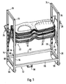
- Fig. 1 shows a transport and storage rack with the features of the invention in the loaded state and Fig. 2 shows the frame in the unloaded state.
- Objects 10 to be stored are deep-drawn art dashboards for dashboards in motor vehicles.
- foils also called skins
- These foils already have a three-dimensional shape, but are inherently unstable. Only after back-foaming takes place after transport do you receive the stiffening necessary for your application.
- the shape of the later stable shape is already determined by the deep-drawing process.
- the transport and storage rack receiving the objects 10 comprises a frame 12 with interconnected upright supports 14, 16, 18 and 20. In these supports 14, 16, 18 and 20, holders 22 for the objects are cascaded one above the other.
- the brackets 22 each consist of a pair of carriers 24 and 26, on which a shell 28 for receiving the objects 10 rests.
- the respective bracket 22 thus includes the arranged at the same level, opposite carriers 24 and 26 and the shell 28 resting on the carriers.
- the height levels of the brackets 22 are expediently arranged such that a unit of five three-dimensional objects lying on a shell 28 projects straight into the upper shell adapted to the shape of the objects 10, but without contact between the shell 28 and the uppermost object 10 the unit below can be done. In this way, a maximum packing density can be achieved without the objects rubbing against one another and being damaged by vibrations when the surface pressure is too high.
- both carriers 24 and 26 of a pair of carriers can be pivoted from a transport position into a rest position. Taking into account a certain disability during loading and unloading, however, it would also be conceivable to make only one carrier 24 or 26 of a pair of carriers movable and to arrange the other firmly.
- each carrier 24, 26 consists of a pair of interconnected support legs 30, 32, which end at one end in support pins 34, 36 and at the other end in support pins 38, 40.
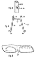
- Fig. 4 shows such a carrier in detail.
- the support pins 34, 36 are angled relative to the support legs 30, 32 so that they provide an approximately horizontal support surface for the shell 28 when the supports 24 and 26 are in the transport position.
- they also fix the shell 28 against slipping sideways and the shell 28 in turn, the top of which is adapted to the shape of the objects 10, fixes the objects. This ensures stable handling of the units from the objects 10 together with the tray 28 as well as in the transport and storage rack together with other units.
- the bearing pins 38 and 40 are also angled relative to the support legs 30 and 32, but in contrast to the support pins 34 and 36 they form a common axis. You can thus intervene in the corresponding support-side bearings 44 and 46 and be stored there. This storage provides the prerequisite for a swiveling movement around a horizontal swivel axis.
- the support legs 30 and 32 are connected in the vicinity of the end on the support pin side by a cross bar 42.
- This crossbar 42 couples the two support legs together, but allows compression of the carrier 24 and 26 at the lower end, so that the journals 38 and 40 can be pressed towards one another and thus be inserted or removed from the supports 44 and 46 in a simple manner these can be removed.
- the carriers 24 and 26 are designed such that the distance between the support legs 30 and 32 decreases from the ends on the journal side to the ends on the journal side.
- the carriers can thus be arranged one inside the other and also pivoted without interfering with one another during the pivoting movement.
- the support-side bearings 44 and 46, in which the journals 38 and 40 of the supports 24 and 26 engage, consist of horizontal bores 48 and 50 which are embedded in the supports 14, 16, 18 and 20.
- FIGS. 1 and 2 In the perspective view of FIGS. 1 and 2 are the bearings of the supports 16 and 20, so that they have not been specified.
- Bores 48 and 50 are framed below and laterally by bearing shells 52 and 54. These bearing shells 52 and 54 project laterally from the supports 14, 16, 18 and 20 inwards.
- the bearing shells 52 and 54 perform several functions. On the one hand, they provide a guide for the journals 38 and 40 when the carriers 24 and 26 are inserted into the bores 48 and 50, which makes assembly easier. On the other hand, they represent a stop for the support legs 30 and 32 in both pivoting end positions, that is to say both in the transport position and in the rest position. Finally, they offer a widened bearing surface for the bearing pins 38 and 40, as a result of which the bearing pins 38 and 40 wear out and the walls of the supports 14, 16, 18 and 20 in the area of the bores 48 and 50 is reduced.
- the frame 12 is provided with rollers 56 and 58 at the lower end. This makes it possible to move the fully loaded transport and storage rack over short distances without that this requires the use of a grant.
- a further embodiment provides tabs 68 on one of the cross members 60, 62, 64 and 66, which connect the upright supports 14, 16, 18 and 20 to one another.
- This tab 68 is used to receive a fork of a forklift truck, around the transport and storage rack e.g. to be lifted from the floor onto the loading area of a truck or unloaded from there. The tab 68 then provides a guide, so that the transport and storage rack cannot slide off the side of the fork during maneuvering movements of the forklift.
- the procedure for loading a transport and storage rack is as follows. First, the three-dimensional plastic films are e.g. placed as units of five pieces on a tray 28, as shown in Fig. 5.
- the shell 28, which is adapted to the shape of the plastic films, is stable in itself, in contrast to these, so that it keeps the films true to shape even when it is only supported by relatively small supporting pins 34 and 36 of the carriers 24 and 26.
- the bowl 28 with the objects 10 is now placed on the two lower supports 24 and 26 in the frame 12.
- these carriers are in the transport position, while all the carriers arranged above them are in the rest position and thereby allow free access to the lower carriers.
- the pair of supports 24 and 26 lying above is pivoted into the transport position and a further unit consisting of objects 10 lying on a tray 28 is placed on these supports.
- the process is then repeated accordingly until all pairs of carriers 24 and 26 are aligned in the transport position and also the upper pairs of carriers 24 and 26 accommodate a unit with objects 10.
- the procedure is expediently carried out in the opposite direction, i.e. the upper unit consisting of objects 10 and tray 28 is lifted and removed and the supports 24 and 26 are then pivoted into the rest position.
Landscapes
- Engineering & Computer Science (AREA)
- Mechanical Engineering (AREA)
- Packaging Of Machine Parts And Wound Products (AREA)
- Toys (AREA)
Abstract
Description
Die Erfindung betrifft ein Transport- und Lagergestell für dreidimensionale, in sich instabile Gegenstände nach dem Oberbegriff des Patentanspruchs 1.The invention relates to a transport and storage rack for three-dimensional, inherently unstable objects according to the preamble of claim 1.
Dreidimensionale Gegenstände der eingangs genannten Art sind z.B. Kunststoffolien für Armaturenbretter in Kraftfahrzeugen. Diese Folien, im Fachjargon als Häute bezeichnet, werden in der Regel in einem Herstellungsbetrieb tiefgezogen und von weiteren Verarbeitungsbetrieben,z.B. Automobilfabriken, durch Hinterschäumen zu einbaufertigen Armaturenbrettern weiterverarbeitet.Three-dimensional objects of the type mentioned above are, for example, plastic films for dashboards in motor vehicles. These foils, referred to in the technical jargon as skins, are generally deep-drawn in a manufacturing plant and further processed by further processing companies, for example automobile factories, by back-foaming to form ready-to-install dashboards.
Beim Transport der Häute in großen Stückzahlen ergibt sich das Problem, sie so zu lagern, daß sie durch die Transporterschütterungen nicht beschädigt werden. Werden nämlich zuviele Häute einfach übereinander gestapelt, so reiben sich weiter unten liegenden Häute im Laufe des Transportes durch die Erschütterungen aneinander und erhalten partial ein unansehnlich glänzendes Aussehen (Speckschwarteneffekt). Um dies zu vermeiden, wurden die Häute bisher in Einheiten zu je fünf Stück übereinander gestapelt und diese Einheiten dann gesondert in Kartons verpackt. Durch die beschriebene Art der Verpackung geht aber sehr viel Lager- und Transportvolumen verloren. So fast ein Euro-LKW-Zug bisher nur etwa 560 derart verpackte Häute, obwohl das zulässige Ladegewicht noch bei weitem nicht ausgeschöpft ist.When transporting the skins in large quantities, the problem arises of storing them in such a way that they are not damaged by the transporter vibrations. If too many skins are simply stacked on top of each other, the skins lying below rub against each other during the transport due to the vibrations and sometimes get an unsightly shiny appearance (bacon rind effect). In order to avoid this, the hides were previously stacked in units of five, and these units were then packed separately in boxes. A lot of storage and transport volume is lost due to the type of packaging described. So almost a euro truck train has only so far about 560 skins packaged in this way, although the permissible loading weight is far from being exhausted.
Der Erfindung liegt die Aufgabe zugrunde, ein Transport- und Lagergestell für dreidimensionale, in sich instabile Gegenstände zu schaffen, welches bei optimaler Schonung der Gegenstände vor Schäden durch Erschütterungen eine sehr hohe Packungsdichte ermöglicht.The invention has for its object to provide a transport and storage rack for three-dimensional, inherently unstable objects, which allows a very high packing density with optimal protection of the objects from damage caused by vibrations.
Diese Aufgabe wird bei einem Transport- und Lagerge stell nach dem Oberbegriff des Anspruchs 1 durch die im kennzeichnenden Teil angegebenen Merkmale gelöst.This task is at a transport and storage area stell solved according to the preamble of claim 1 by the features specified in the characterizing part.
Das Transport- und Lagergestell nach der Erfindung ermöglicht es, die dreidimensionalen Gegenstände, z.B. in gleichen Einheiten von jeweils fünf Stück wie bei der vorbeschriebenen Verpackungsart, mittels der kaskadiert übereinander angeordneten Halterungen ineinander zu lagern, ohne daß jedoch eine Berührung und Reibung unterschiedlicher Einheiten erfolgt. Durch das Ineinanderlagern der Einheiten wird im Gegensatz der Verpackungen in Kartons für jede Einheit eine Lager- und Transportvolumeneinsparung erzielt, die etwa der Grundfläche der Gegenstände multipliziert mit der maximalen Erhebung eines der Gegenstände entspricht.The transport and storage rack according to the invention enables the three-dimensional objects, e.g. in the same units of five pieces each as in the above-described type of packaging, by means of the cascaded superposed brackets one inside the other, but without contact and friction between different units. In contrast to the packaging in boxes, the storage of the units in one another results in a saving in storage and transport volume, which corresponds approximately to the base area of the objects multiplied by the maximum elevation of one of the objects.
Im Zusammenhang mit den insbesondere erwähnten Häuten für Armaturenbretter in Kraftfahrzeugen steigert das erfindungsgemäße Transport- und Lagergestell die Transportkapazität von Euro-LKW-Zügen von 560 auf 2.000 Häute.In connection with the particularly mentioned skins for dashboards in motor vehicles, the transport and storage rack according to the invention increases the transport capacity of Euro truck trains from 560 to 2,000 skins.
Die Erfindung führt somit zu einer erheblichen Transportkosteneinsparung. In Folge des verringerten Transportvolumens für die gleiche Anzahl von Gegenständen sinkt auch der benötigte Lagerraum, wenn die Gegenstände vor und/oder nach dem Transport zwischengelagert werden müssen. Außerdem entfällt das arbeitsintensive Verpacken der Gegenstände in Kartons und das Verkleben derselben, das anschließende Öffnen, Auspacken sowie die Handhabung des leeren Kartonmaterials oder der relativ kleinen Verpackungseinheiten.The invention thus leads to a considerable saving in transport costs. As a result of the reduced transport volume for the same number of items the required storage space also drops if the objects have to be temporarily stored before and / or after transport. In addition, there is no labor-intensive packaging of the objects in boxes and gluing them, the subsequent opening, unpacking and handling of the empty cardboard material or the relatively small packaging units.
Vorzugsweise bestehen die Halterungen jeweils aus einem Paar Träger, auf denen eine Schale zur Aufnahme der Gegenstände aufliegt.The brackets preferably each consist of a pair of supports on which a tray for receiving the objects rests.
Da bei dieser Ausgestaltung der Halterungen die Schale die Abstützung und Formerhaltung der Gegenstände übernimmt, können die Träger mit verhältnismäßig geringen Auflageflächen ausgestattet werden und somit klein und beweglich gestaltet werden.In this embodiment of the holders, since the shell supports and maintains the shape of the objects, the supports can be equipped with relatively small contact surfaces and can thus be made small and mobile.
Vorzugsweise ist die Oberseite der Schale der Form der Gegenstände angepaßt.The top of the shell is preferably adapted to the shape of the objects.
Auf diese Weise wird erreicht, daß die Gegenstände ganzflächig unterstützt werden und somit keine Knickung oder starke Flächenbelastung einzelner Be reiche zu erwarten ist, die dann zu eventuellen Schäden führen könnte. Weiterhin wird bei dreidimensionalen Gegenständen diese Ausgestaltung formschlüssig, so daß ein Hin- und Herrutschen der Gegenstände auf der Schale verhindert wird.In this way it is achieved that the objects are supported over the entire surface and thus no kinking or heavy surface loading of individual loading rich is to be expected, which could then lead to possible damage. Furthermore, in the case of three-dimensional objects, this configuration becomes form-fitting, so that the objects cannot slide back and forth on the shell.
Eine praktische Ausgestaltung der Träger sieht vor, daß diese jeweils aus einem Paar untereinander verbundener Tragschenkel bestehen, die an einem Ende in Tragzapfen und am anderen Ende in Lagerzapfen auslaufen.A practical embodiment of the carrier provides that they each consist of a pair of interconnected support legs, which end at one end in trunnions and at the other end in trunnions.
Es wird durch diese Ausgestaltung erreicht, daß die Träger ohne gegenseitige Störung in der örtlichen Anordnung und gegebenenfalls Beweglichkeit in die Schalen zur Aufnahme der Gegenstände eingreifen können und dabei einen sehr geringen Abstand mit der Folge einer hohen Packungsdichte zwischen dem obersten Gegenstand einer Einheit und der darüber befindlichen Schale sicherzustellen.It is achieved by this configuration that the carrier can intervene in the shells for receiving the objects without mutual interference in the local arrangement and possibly mobility and a very small distance with the consequence of a high packing density between the uppermost object of a unit and the one above it ensure the existing shell.
In weiterer Ausgestaltung der Tragschenkel sind diese in der Nähe des tragzapfenseitigen Endes durch einen Querstab verbunden.In a further embodiment of the support legs, these are connected by a cross bar in the vicinity of the end on the support pin side.
Die Tragschenkel sind durch diese Maßnahme zwar während des Halterns und bei der Handhabung gekoppelt, es ist jedoch möglich, die tragazapfenseitigen Enden zusammenzudrücken, um so einen oder mehrere Tragschenkel mit ihren Lagerzapfen in entsrprechende Lager des Rahmens einzusetzen oder aus diesen herauszunehmen. Ein solcher Vorgang findet einmal bei der Erstmontage statt, kann aber auch erforderlich sein, wenn die besondere Ausgestaltung der Gegenstände eine entsprechende Ausgestaltung der Träger vorsieht und damit der Austausch anders ausgestalteter Träger erforderlich ist. Eine bevorzugte Ausgestaltung sieht vor, daß die Tragzapfen die Schale untergreifen.The support legs are coupled by this measure during holding and handling, but it is possible to compress the ends of the trunnion pin in order to insert or remove one or more support legs with their trunnions in corresponding bearings in the frame. Such a process takes place once during the initial assembly, but may also be necessary if the special design of the objects provides for a corresponding design of the supports and thus the replacement of differently designed supports is necessary. A preferred embodiment provides that the support pins engage under the shell.
Damit können bei untereschiedlichen Variationsmöglichkeiten der Gegenstände in vielen Fällen dieselben Träger verwendet werden, da es bei ihrer Form nicht darauf ankommt, die Gegenstände selbst zu haltern, sondern lediglich die die Gegenstände unterstützende Schale zu haltern.In many cases, the same carriers can thus be used with different possibilities of variation of the objects, since their shape does not make it important to hold the objects themselves, but rather only to hold the shell supporting the objects.
Beim Untergreifen der Schale wird außerdem sichergestellt, daß wegen der dreidimensionalen Ausbildung der der Form der Gegenstände angepaßten Schale auch eine Fixierung der Schale bezüglich der Träger gegen Verrutschen erfolgt.When reaching under the shell, it is also ensured that due to the three-dimensional design of the shell adapted to the shape of the objects, the shell is also fixed with respect to the carrier Slipping takes place.
Vorzugsweise sind die Lagerzapfen in stützenseitigen Lagern gelagert.The bearing journals are preferably mounted in bearings on the support side.
Durch diese Maßnahme wird erreicht, daß die Träger relativ zu den Stützen beweglich sind und so die Möglichkeit geschaffen ist, einmal eine Arbeitslage vorzusehen, in der die Schalen mit den Gegenständen auf die Träger aufgelegt werden können und eine Ruhelage, in der die darin befindlichen Träger den Ladevorgang der Schalen mit Gegenständen auf die in der Arbeitslage befindlichen Träger nicht stören.This measure ensures that the supports are movable relative to the supports, thus creating the possibility of providing a working position in which the trays with the objects can be placed on the supports and a rest position in which the supports located therein are do not interfere with the loading of the trays with objects on the supports in the working position.
Bei einer praktischen Ausgestaltung der Erfindung nimmt der Abstand der Tragschenkel jedes Trägers von den lagerzapfenseitigen Enden zu den tragzapfenseitigen Enden ab.In a practical embodiment of the invention, the distance between the support legs of each carrier decreases from the journal-side ends to the journal-side ends.
Diese teilweise keilförmige Ausgestaltung der Tragschenkel ermöglicht es, eine Schwenkbewegung jedes einzelnen Trägers auszuführen, ohne daß dadurch eine Kollision mit den anderen benachbarten Trägern zustande kommt. Die Träger können also in kurzem Abstand übereinander bewegt werden, wobei sie mit ih ren Schenkeln den von den Schenkeln des darüberliegenden Trägers gebildeten Zwischenraum durchwandern können bzw. für einen darunterliegenden Träger einen solchen Zwischenraum schaffen.This partially wedge-shaped configuration of the support legs makes it possible to perform a pivoting movement of each individual carrier without causing a collision with the other neighboring carriers. The carriers can thus be moved one above the other at a short distance, with them using ih Ren legs can pass through the space formed by the legs of the overlying carrier or create such a space for an underlying carrier.
Eine besonders zweckmäßige Ausgestaltung sieht vor, daß die stützenseitigen Lager aus in die Stützen eingelassenen, waagerechten Bohrungen sowie aus die Bohrungen unten und seitlich umrahmenden, auf den Stützen angeordneten Lagerschalen bestehen.A particularly expedient embodiment provides that the support-side bearings consist of horizontal bores embedded in the supports as well as bearing shells which frame the bores below and laterally and are arranged on the supports.
Die Bohrungen in den Stützen stellen einmal eine sehr einfache und leicht herzustellende Ausgestaltung der Lager dar. Die Lagerschalen erleichtern das Einsetzen der Lagerzapfen in die Bohrungen, indem die Träger einfach unter Zusammendrücken der Tragschenkel auf die Lagerschalen aufgelegt werden brauchen und losgelassen werden können. Dabei gleiten dann die Lagerzapfen der Tragschenkel automatisch in die waagerechten Bohrungen der Stützen ein. Beim Einsetzen der Träger übernehmen die Lagerschalen zudem eine seitliche Führung.The holes in the supports represent a very simple and easy-to-manufacture design of the bearings. The bearing shells make it easier to insert the trunnions into the holes by simply pressing the supports onto the bearing shells by pressing the support legs and releasing them. The bearing journal of the support legs then automatically slide into the horizontal holes in the supports. When inserting the carrier, the bearing shells also take over a lateral guidance.
Bei einer Weiterbildung liegen die Tragschenkel der Träger an einer der Flanken der Lagerschalen an.In a further development, the carrier legs of the carriers rest on one of the flanks of the bearing shells.
Bei gleicher Ausgestaltung der Lagerschalen übernehmen die Flanken somit auch einen Begrenzungsanschlag für die Schwenkbewegung der Träger. Dabei stellt die eine Flanke eine Schwenkendstellung der Träger dar, welcher einer Arbeitsstellung entspricht und die andere Flanke sorgt für eine Schwenkendstellung, die einer Ruhestellung entspricht.With the same configuration of the bearing shells, the flanks also assume a limit stop for the pivoting movement of the carrier. One flank represents a pivoting end position of the carrier, which corresponds to a working position, and the other flank provides a pivoting end position, which corresponds to a rest position.
Eine sehr zweckmäßige Weiterbildung der Erfindung sieht vor, daß der Rahmen am unteren Ende mit Rollen versehen ist.A very useful development of the invention provides that the frame is provided with rollers at the lower end.
Es ist dann möglich, den Rahmen auch im voll beladenen Zustand noch ohne große Mühe oder unter Zuhilfenahme eines Werkzeuges zu verschieben. Eine solche Verschiebung kann z.B. erforderlich sein, um ein Transport- und Lagergestell aus einer Mehrzahl gleichartiger Transport- und Lagergestelle herauszunehmen, in eine Lücke hineinzuschieben oder entsprechende Korrekturverschiebungen bei der Be- und Entladung eines LKW vorzunehmen.It is then possible to move the frame even when fully loaded with little effort or with the help of a tool. Such a shift can e.g. be necessary in order to remove a transport and storage rack from a plurality of similar transport and storage racks, to insert it into a gap or to make corresponding correction shifts when loading and unloading a truck.
Eine praktische Weiterbildung sieht vor, daß der Rahmen an seinen Quertraversen zur Verbindung der aufrechten Stützen mit wenigstens einer Lasche zur Aufnahme einer Gabel eines Gabelstaplers versehen ist.A practical development provides that the frame on its cross members for connecting the upright supports with at least one bracket Recording a fork of a forklift is provided.
Diese Ausgestaltung ist zweckmäßig, um einmal dem Gabelstaplerfahrer Anhaltspunkte zu bieten, wo er den Rahmen zweckmäßig aufnimmt, zum anderen den Rahmen bei der Aufnahme auf die Gabel oder beim Transport mit dem Gabelstapler gegen Verrutschen zu sichern.This configuration is useful in order to provide the forklift driver with clues where he expediently picks up the frame, and on the other hand to secure the frame against slipping when it is picked up on the fork or during transport with the forklift.
Außerdem ist bei einer praktischen Weiterbildung vorgesehen, daß die Stützen mit Aufnahmeöffnungen für Kupplungsklammern versehen sind.In addition, it is provided in a practical development that the supports are provided with receiving openings for coupling brackets.
Diese Weiterbildung ist zweckmäßig, um mehrere Transport- und Lagergestelle z. B. beim Transport im LKW miteinander fest zu verbinden, so daß die Rahmen nicht gegeneinander schlagen und es dabei zu besonders abrupten Bewegungen der zu transportierenden Gegenstände kommt, die dann durch die extremen Impulsbelastungen bei langen Transportwegen auch zu Beschädigungen der Oberfläche führen können.This training is useful to z several transport and storage racks. B. firmly connected to each other during transport in the truck, so that the frame does not hit against each other and there are particularly abrupt movements of the objects to be transported, which can then lead to damage to the surface due to the extreme impulse loads on long transport routes.
Weiterbildungen und vorteilhafte Ausgestaltungen der Erfindung ergeben sich aus den Ansprüchen, der Beschreibung und der Zeichnung, die ein Ausführungsbeispiel veranschaulicht.Further developments and advantageous refinements of the invention result from the claims, the description and the drawing, which illustrates an exemplary embodiment.
In der Zeichnung zeigen:
- Fig. 1 eine perspektivische Ansicht eines Transport- und Lagergestells nach der Erfindung im beladenen Zustand,
- Fig. 2 eine perspektivische Ansicht eines Transport- und Lagergestells nach der Erfindung im unbeladenen Zustand,
- Fig. 3 eine Teilansicht aus Fig. 1 oder 2, welche ein stützenseitiges Lager zeigt,
- Fig. 4 einen einzelnen Träger, und
- Fig. 5 eine perspektivische Ansicht einer Schale.
- 1 is a perspective view of a transport and storage rack according to the invention in the loaded state,
- 2 is a perspective view of a transport and storage rack according to the invention in the unloaded state,
- 3 is a partial view of FIG. 1 or 2, which shows a support-side bearing,
- Fig. 4 shows a single carrier, and
- Fig. 5 is a perspective view of a shell.
Fig. 1 zeigt ein Transport- und Lagergestell mit den Merkmalen der Erfindung im beladenen Zustand und Fig. 2 das Gestell im unbeladenen Zustand. Bei zu lagernden Gegenständen 10 handelt es sich um tiefgezogenen Kunst stoffolien für Armaturenbretter in Kraftfahrzeugen.Fig. 1 shows a transport and storage rack with the features of the invention in the loaded state and Fig. 2 shows the frame in the unloaded state.
Diese Folien, auch als Häute bezeichnet, weisen bereits eine dreidimensionale Form auf, sind in sich aber instabil. Erst durch eine nach dem Transport stattfindende Hinterschäumung erhalten sie die für ihren Anwendungszweck nötige Aussteifung. Die Ausprägung der späteren stabilen Form ist aber bereits durch den Tiefziehvorgang vorgegeben.These foils, also called skins, already have a three-dimensional shape, but are inherently unstable. Only after back-foaming takes place after transport do you receive the stiffening necessary for your application. The shape of the later stable shape is already determined by the deep-drawing process.
Das die Gegenstände 10 aufnehmende Transport- und Lagergestell umfaßt einen Rahmen 12 mit untereinander verbundenen aufrechten Stützen 14, 16, 18 und 20. In diesen Stützen 14, 16, 18 und 20 sind Halterungen 22 für die Gegenstände kaskadiert übereinander gelagert.The transport and storage rack receiving the
Die Halterungen 22 bestehen jeweils aus einem Paar Träger 24 und 26, auf denen eine Schale 28 zur Aufnahme der Gegenstände 10 aufliegt. Zur jeweiligen Halterung 22 gehören also die auf gleichem Höhen niveau angeordneten, gegenüberliegenden Träger 24 und 26 sowie die auf den Trägern aufliegende Schale 28.The
Die Höhenniveaus der Halterungen 22 sind zweckmäßig so angeordnet, daß eine Einheit von jeweils fünf dreidimensionalen Gegenständen auf einer Schale 28 aufliegend gerade in die der Form der Gegenstände 10 angepaßte obenliegende Schale hineinragt, ohne daß jedoch eine Berührung zwischen der Schale 28 und dem obersten Gegenstand 10 der darunter befindlichen Einheit erfolgen kann. Auf diese Weise läßt sich eine maximale Packungsdichte erzielen, ohne daß die Gegenstände durch Erschütterungen bei zu hohem Flächendruck aneinander reiben und Schaden nehmen können.The height levels of the
Bei dem dargestellten Transport- und Lagergestell sind acht unterschiedliche Höhenniveaus angedeutet, wobei in drei Höhenniveaus Trägerpaare 24 und 26 eine Transportstellung und ein Trägerpaar 24 und 26 eine Ruhestellung einnehmen. Für den Lade- und Entladevorgang ist es zweckmäßig, wenn beide Träger 24 und 26 eines Trägerpaars von einer Transportstellung in eine Ruhestellung verschwenkt werden können. Unter Inkaufnahme einer gewissen Behinderung beim Be- und Entladen wäre es jedoch auch denkbar, nur einen Träger 24 oder 26 eines Trägerpaares beweglich auszubilden, und den anderen fest anzuordnen.In the illustrated transport and storage rack, eight different height levels are indicated, with three pairs of
Im einzelnen besteht jeder Träger 24, 26 aus einem Paar untereinander verbundener Tragschenkel 30, 32, die an einem Ende in Tragzapfen 34, 36 und am anderen Ende in Lagerzapfen 38,40 auslaufen. Fig. 4 zeigt einen solchen Träger im Detail. Die Tragzapfen 34, 36 sind gegenüber den Tragschenkeln 30,32 abgewinkelt, so daß sie eine etwa waagerechte Auflagefläche für die Schale 28 darbieten, wenn sich die Träger 24 und 26 in der Transportstellung befinden. Gleichzeitig fixieren sie auch die Schale 28 gegen seitliches Verrutschen und die Schale 28 wiederum, deren Oberseite der Form der Gegenstände 10 angepaßt ist, fixiert die Gegenstände. Somit ist eine stabile Handhabung der Einheiten aus den Gegenständen 10 zusammen mit der Schale 28 für sich als auch im Transport- und Lagergestell zusammen mit anderen Einheiten gewährleistet.In particular, each
Die Lagerzapfen 38 und 40 sind ebenfalls gegenüber den Tragschenkeln 30 und 32 abgewinkelt, wobei sie jedoch im Gegensatz zu den Tragzapfen 34 und 36 eine gemeinsame Achse bilden. Sie können damit in entsprechende stützenseitige Lager 44 und 46 eingreifen und dort drin gelagert werden. Diese Lagerung bietet die Voraussetzung für eine Schwenkbewegung um eine waagerechte Schwenkachse.The bearing pins 38 and 40 are also angled relative to the
Wie die Zeichnung erkennen läßt, sind die Tragschenkel 30 und 32 in der Nähe des tragzapfenseitigen Endes durch einen Querstab 42 verbunden. Dieser Querstab 42 koppelt die beiden Tragschenkel miteinander, erlaubt aber ein Zusammendrücken des Trägers 24 und 26 am unteren Ende, so daß die Lagerzapfen 38 und 40 aufeinanderzu gedrückt werden können und so in einfacher Weise in die stützenseitigen Lager 44 und 46 eingesetzt werden bzw. aus diesen herausgenommen werden können.As can be seen in the drawing, the
Die Träger 24 und 26 sind so ausgebildet, daß der Abstand der Tragschenkel 30 und 32 von den lagerzapfenseitigen Enden zu den tragzapfenseitigen Enden abnimmt. Die Träger können somit ineinander angeordnet und auch verschwenkt werden, ohne daß sie sich bei der Schwenkbewegung gegenseitig stören.The
Die stützenseitigen Lager 44 und 46, in die die Lagerzapfen 38 und 40 der Träger 24 und 26 eingreifen, bestehen aus waagerechten Bohrungen 48 und 50, die in die Stützen 14, 16, 18 und 20 eingelassen sind. In der perspektivischen Darstellung der Figuren 1 und 2 sind die Lager der Stützen 16 und 20, so daß sie nicht näher bezeichnet wurden.The support-
Die Bohrungen 48 und 50 werden unten und seitlich von Lagerschalen 52 und 54 umrahmt. Diese Lagerschalen 52 und 54 stehen seitlich von den Stützen 14, 16, 18 und 20 nach innen vor.Bores 48 and 50 are framed below and laterally by bearing shells 52 and 54. These bearing shells 52 and 54 project laterally from the
Die Lagerschalen 52 und 54 erfüllen mehrere Funktionen. Einmal bieten sie den Lagerzapfen 38 und 40 beim Einsetzen der Träger 24 und 26 in die Bohrungen 48 und 50 eine Führung, wodurch die Montage erleichtert wird. Zum anderen stellen sie für die Tragschenkel 30 und 32 in beiden Schwenkendstellungen, also sowohl in der Transportstellung als auch in der Ruhestellung, einen Anschlag dar. Schließlich bieten sie eine verbreitert Auflagefläche für die Lagerzapfen 38 und 40, wodurch die Abnutzung der Lagerzapfen 38 und 40 sowie die Wandungen der Stützen 14, 16, 18 und 20 im Bereich der Bohrungen 48 und 50 verringert wird.The bearing shells 52 and 54 perform several functions. On the one hand, they provide a guide for the
Weiterhin ist vorgesehen, daß der Rahmen 12 am unteren Ende mit Rollen 56 und 58 versehen ist. Dadurch ist es möglich, das voll beladene Transport- und Lagergestell über kurze Strecken zu verschieben, ohne daß dazu die Inanspruchnahme eines Fördermittels erforderlich ist.It is also provided that the
Eine weitere Ausgestaltung sieht Laschen 68 an einer der Quertraversen 60, 62, 64 und 66 vor, welche die aufrechten Stützen 14, 16, 18 und 20 miteinander verbinden.A further embodiment provides
Diese Lasche 68 dient zur Aufnahme einer Gabel eines Gabelstaplers, um das Transport- und Lagergestell z.B. vom Boden auf die Ladefläche eines LKW zu heben oder von dort zu entladen. Die Lasche 68 bietet dann eine Führung, so daß bei Rangierbewegungen des Gabelstaplers das Transport- und Lagergestell nicht von der Gabel seitlich herunterrutschen kann.This
An den Stützen 14, 16, 18 und 20 befinden sich Aufnahmeöffnungen 70, 72, 74 und 76, in die Kupplungsklammern gesteckt werden können. Mit deren Hilfe lassen sich dann mehrere, auf der Ladefläche eines LKW stehende Transport- und Lagergestelle miteinander verbinden, so daß sie eine stabile Einheit bilden und ein Gegeneinanderschlagen der Rahmen 12 beim Transport verhindert wird.On the
Beim Beladen eines Transport- und Lagergestells wird wie folgt vorgegangen. Zunächst werden die dreidimensionalen Kunststoffolien z.B. als Einheiten zu je fünf Stück auf jeweils eine Schale 28 gelegt, wie sie in Fig. 5 dargestellt ist. Die Schale 28, die der Form der Kunststoffolien angepaßt ist, ist im Gegensatz zu diesen in sich stabil, so daß sie die Folien auch dann formgerecht hält, wenn sie nur von relativ kleinen Tragzapfen 34 und 36 der Träger 24 und 26 unterstützt wird.The procedure for loading a transport and storage rack is as follows. First, the three-dimensional plastic films are e.g. placed as units of five pieces on a
Die Schale 28 mit den Gegenständen 10 wird nun auf die beiden unteren Träger 24 und 26 im Rahmen 12 aufgelegt. Dazu befinden sich diese Träger in der Transportstellung, während alle darüber angeordneten Träger in der Ruhestellung liegen und dadurch den freien Zugang zu den unteren Trägern ermöglichen.The
Anschließend wird das darüber liegende Trägerpaar 24 und 26 in die Transportstellung verschwenkt und eine weitere Einheit aus auf einer Schale 28 liegenden Gegenständen 10 auf diese Träger gesetzt. Der Vorgang wird dann entsprechend wiederholt, bis alle Trägerpaare 24 und 26 in der Transportstellung ausgerichtet sind und auch die oberen Trägerpaare 24 und 26 eine Einheit mit Gegenständen 10 aufnehmen.Subsequently, the pair of
Beim Entladen wird zweckmäßig in umgekehrter Richtung vorgegangen, d.h., es wird jeweils die obere Einheit aus Gegenständen 10 und Schale 28 angehoben und entfernt und anschließend die Träger 24 und 26 in die Ruhestellung verschwenkt.When unloading, the procedure is expediently carried out in the opposite direction, i.e. the upper unit consisting of
Claims (13)
Applications Claiming Priority (2)
| Application Number | Priority Date | Filing Date | Title |
|---|---|---|---|
| DE3841539A DE3841539C2 (en) | 1988-12-09 | 1988-12-09 | Transport and storage rack for flat objects |
| DE3841539 | 1988-12-09 |
Publications (3)
| Publication Number | Publication Date |
|---|---|
| EP0372191A2 true EP0372191A2 (en) | 1990-06-13 |
| EP0372191A3 EP0372191A3 (en) | 1990-12-12 |
| EP0372191B1 EP0372191B1 (en) | 1993-11-03 |
Family
ID=6368824
Family Applications (1)
| Application Number | Title | Priority Date | Filing Date |
|---|---|---|---|
| EP89118563A Expired - Lifetime EP0372191B1 (en) | 1988-12-09 | 1989-10-06 | Transporting and storage rack for three-dimensional unstable objects |
Country Status (3)
| Country | Link |
|---|---|
| EP (1) | EP0372191B1 (en) |
| DE (2) | DE3841539C2 (en) |
| ES (1) | ES2049294T3 (en) |
Cited By (3)
| Publication number | Priority date | Publication date | Assignee | Title |
|---|---|---|---|---|
| EP0442780A1 (en) * | 1990-02-06 | 1991-08-21 | Saint-Gobain Vitrage International | Pallet for transport of glass panels |
| GB2386101A (en) * | 2002-03-04 | 2003-09-10 | Honda Canada Inc | Transport device |
| CN112061544A (en) * | 2020-10-12 | 2020-12-11 | 芜湖市元山机械制造有限公司 | Auxiliary frame packaging device and packaging method thereof |
Families Citing this family (3)
| Publication number | Priority date | Publication date | Assignee | Title |
|---|---|---|---|---|
| DE9408630U1 (en) * | 1994-05-26 | 1995-04-13 | Hoechst Ag, 65929 Frankfurt | Packaging system for sensitive bulk goods |
| DE29806027U1 (en) * | 1998-04-02 | 1998-06-04 | REHAU AG + Co., 95111 Rehau | Storage and transport system |
| DE20215085U1 (en) * | 2002-09-24 | 2004-02-19 | Metallverarbeitung Kögel GmbH | Transport and washing device, especially for workpieces, comprises base and frame joined together by connecting parts used to hold workpieces |
Citations (3)
| Publication number | Priority date | Publication date | Assignee | Title |
|---|---|---|---|---|
| US4368675A (en) * | 1978-11-13 | 1983-01-18 | Herman Miller, Inc. | Stacking pallet |
| JPS60128105A (en) * | 1983-12-13 | 1985-07-09 | Nakamoto Tekko:Kk | Shelf fitting structure |
| DE8710875U1 (en) * | 1986-08-11 | 1987-10-15 | Struckhoff, Hartmut, 2814 Bruchhausen-Vilsen | Device for storing parts at a distance from each other |
Family Cites Families (1)
| Publication number | Priority date | Publication date | Assignee | Title |
|---|---|---|---|---|
| DE1122000B (en) * | 1959-07-25 | 1962-01-11 | Demag Zug Gmbh | Device for the intermittent stacking of flat goods of the same size, especially sheet metal packages |
-
1988
- 1988-12-09 DE DE3841539A patent/DE3841539C2/en not_active Expired - Fee Related
-
1989
- 1989-10-06 EP EP89118563A patent/EP0372191B1/en not_active Expired - Lifetime
- 1989-10-06 DE DE89118563T patent/DE58906106D1/en not_active Expired - Fee Related
- 1989-10-06 ES ES89118563T patent/ES2049294T3/en not_active Expired - Lifetime
Patent Citations (3)
| Publication number | Priority date | Publication date | Assignee | Title |
|---|---|---|---|---|
| US4368675A (en) * | 1978-11-13 | 1983-01-18 | Herman Miller, Inc. | Stacking pallet |
| JPS60128105A (en) * | 1983-12-13 | 1985-07-09 | Nakamoto Tekko:Kk | Shelf fitting structure |
| DE8710875U1 (en) * | 1986-08-11 | 1987-10-15 | Struckhoff, Hartmut, 2814 Bruchhausen-Vilsen | Device for storing parts at a distance from each other |
Non-Patent Citations (1)
| Title |
|---|
| PATENT ABSTRACTS OF JAPAN, Band 9, Nr. 286 (M-429)[2009], 13. November 1985; & JP-A-60 128 105 (NAKAMOTO TETSUKOU K.K.) 09-07-1985 * |
Cited By (6)
| Publication number | Priority date | Publication date | Assignee | Title |
|---|---|---|---|---|
| EP0442780A1 (en) * | 1990-02-06 | 1991-08-21 | Saint-Gobain Vitrage International | Pallet for transport of glass panels |
| GB2386101A (en) * | 2002-03-04 | 2003-09-10 | Honda Canada Inc | Transport device |
| GB2386101B (en) * | 2002-03-04 | 2004-06-23 | Honda Canada Inc | Transport device |
| US6991412B2 (en) | 2002-03-04 | 2006-01-31 | Honda Canada, Inc. | Transport device |
| US7338238B2 (en) | 2002-03-04 | 2008-03-04 | Honda Canada, Inc. | Transport device |
| CN112061544A (en) * | 2020-10-12 | 2020-12-11 | 芜湖市元山机械制造有限公司 | Auxiliary frame packaging device and packaging method thereof |
Also Published As
| Publication number | Publication date |
|---|---|
| EP0372191A3 (en) | 1990-12-12 |
| DE3841539A1 (en) | 1990-06-13 |
| DE3841539C2 (en) | 1994-04-07 |
| DE58906106D1 (en) | 1993-12-09 |
| EP0372191B1 (en) | 1993-11-03 |
| ES2049294T3 (en) | 1994-04-16 |
Similar Documents
| Publication | Publication Date | Title |
|---|---|---|
| EP2686258B1 (en) | Overhead conveyor and method for the automated unloading of a transport bag | |
| DE69603251T2 (en) | CONTAINER FOR USE WITH A CARRIAGE AND SYSTEM CONSTRUCTING A CONTAINER TOGETHER WITH A CART | |
| EP1174374B1 (en) | Device and method for handling articles, especially baggage | |
| AT520517A4 (en) | Unloading station and method for unloading a conveyed goods container loaded with a conveyed item | |
| DE69903257T2 (en) | TRANSPORTER | |
| EP2436621A2 (en) | Retail supply system | |
| EP0372191B1 (en) | Transporting and storage rack for three-dimensional unstable objects | |
| DE19916050A1 (en) | Pallet support and transport frame for boxes of goods | |
| EP2746193B1 (en) | Vehicle for a warehouse, stacker crane, warehouse and corresponding method | |
| EP0678462B1 (en) | High-rise storage rack | |
| EP2672037B1 (en) | Loading system | |
| EP2452900B1 (en) | Rollcontainer loading station, commissioning system with such a station and corresponding methods | |
| EP1538092A1 (en) | Transport system | |
| DE69925622T2 (en) | Vehicle for heavy objects and range for coil-shaped heavy objects | |
| EP1180491B1 (en) | Stacker crane | |
| EP0672569B1 (en) | Shopping trolley | |
| DE2649318C3 (en) | Flat pallet for the transport of workpieces | |
| EP1562831A2 (en) | Device for storing and transporting unit loads and insert for said device | |
| EP0510405B1 (en) | Storage device for storing articles in a stacked or grouped form | |
| DE3716154A1 (en) | Transport container for bumpers for automobile bodies | |
| EP1862405B1 (en) | Method for gripping piece goods using gripper devices of an input and output system and device therefor | |
| DE69813900T2 (en) | METHOD AND DEVICE FOR THE INTERMEDIATE STORAGE OF PRINTED PRODUCTS | |
| DE19707066C2 (en) | Wheel mounting device | |
| DE2164237A1 (en) | Stacking method and device | |
| DE69521000T2 (en) | Containers with self-locking arms, suitable for storing rolling objects |
Legal Events
| Date | Code | Title | Description |
|---|---|---|---|
| PUAI | Public reference made under article 153(3) epc to a published international application that has entered the european phase |
Free format text: ORIGINAL CODE: 0009012 |
|
| AK | Designated contracting states |
Kind code of ref document: A2 Designated state(s): BE DE ES FR GB IT LU NL SE |
|
| PUAL | Search report despatched |
Free format text: ORIGINAL CODE: 0009013 |
|
| AK | Designated contracting states |
Kind code of ref document: A3 Designated state(s): BE DE ES FR GB IT LU NL SE |
|
| 17P | Request for examination filed |
Effective date: 19901102 |
|
| 17Q | First examination report despatched |
Effective date: 19920717 |
|
| GRAA | (expected) grant |
Free format text: ORIGINAL CODE: 0009210 |
|
| AK | Designated contracting states |
Kind code of ref document: B1 Designated state(s): BE DE ES FR GB IT LU NL SE |
|
| ITF | It: translation for a ep patent filed | ||
| REF | Corresponds to: |
Ref document number: 58906106 Country of ref document: DE Date of ref document: 19931209 |
|
| ET | Fr: translation filed | ||
| GBT | Gb: translation of ep patent filed (gb section 77(6)(a)/1977) |
Effective date: 19931231 |
|
| REG | Reference to a national code |
Ref country code: ES Ref legal event code: FG2A Ref document number: 2049294 Country of ref document: ES Kind code of ref document: T3 |
|
| PLBE | No opposition filed within time limit |
Free format text: ORIGINAL CODE: 0009261 |
|
| STAA | Information on the status of an ep patent application or granted ep patent |
Free format text: STATUS: NO OPPOSITION FILED WITHIN TIME LIMIT |
|
| PG25 | Lapsed in a contracting state [announced via postgrant information from national office to epo] |
Ref country code: GB Effective date: 19941006 |
|
| PG25 | Lapsed in a contracting state [announced via postgrant information from national office to epo] |
Ref country code: SE Effective date: 19941007 Ref country code: ES Free format text: LAPSE BECAUSE OF NON-PAYMENT OF DUE FEES Effective date: 19941007 |
|
| 26N | No opposition filed | ||
| PG25 | Lapsed in a contracting state [announced via postgrant information from national office to epo] |
Ref country code: LU Free format text: LAPSE BECAUSE OF NON-PAYMENT OF DUE FEES Effective date: 19941031 Ref country code: BE Effective date: 19941031 |
|
| EAL | Se: european patent in force in sweden |
Ref document number: 89118563.9 |
|
| BERE | Be: lapsed |
Owner name: J. H. BENECKE A.G. Effective date: 19941031 |
|
| PG25 | Lapsed in a contracting state [announced via postgrant information from national office to epo] |
Ref country code: NL Effective date: 19950501 |
|
| GBPC | Gb: european patent ceased through non-payment of renewal fee |
Effective date: 19941006 |
|
| NLV4 | Nl: lapsed or anulled due to non-payment of the annual fee | ||
| PG25 | Lapsed in a contracting state [announced via postgrant information from national office to epo] |
Ref country code: FR Effective date: 19950630 |
|
| PG25 | Lapsed in a contracting state [announced via postgrant information from national office to epo] |
Ref country code: DE Effective date: 19950701 |
|
| EUG | Se: european patent has lapsed |
Ref document number: 89118563.9 |
|
| REG | Reference to a national code |
Ref country code: FR Ref legal event code: ST |
|
| REG | Reference to a national code |
Ref country code: ES Ref legal event code: FD2A Effective date: 19951113 |
|
| PG25 | Lapsed in a contracting state [announced via postgrant information from national office to epo] |
Ref country code: IT Free format text: LAPSE BECAUSE OF NON-PAYMENT OF DUE FEES;WARNING: LAPSES OF ITALIAN PATENTS WITH EFFECTIVE DATE BEFORE 2007 MAY HAVE OCCURRED AT ANY TIME BEFORE 2007. THE CORRECT EFFECTIVE DATE MAY BE DIFFERENT FROM THE ONE RECORDED. Effective date: 20051006 |