EP0371205A2 - Transfer Device - Google Patents
Transfer Device Download PDFInfo
- Publication number
- EP0371205A2 EP0371205A2 EP89115344A EP89115344A EP0371205A2 EP 0371205 A2 EP0371205 A2 EP 0371205A2 EP 89115344 A EP89115344 A EP 89115344A EP 89115344 A EP89115344 A EP 89115344A EP 0371205 A2 EP0371205 A2 EP 0371205A2
- Authority
- EP
- European Patent Office
- Prior art keywords
- pickup
- workpiece
- location
- arc
- along
- Prior art date
- Legal status (The legal status is an assumption and is not a legal conclusion. Google has not performed a legal analysis and makes no representation as to the accuracy of the status listed.)
- Granted
Links
Images


Classifications
-
- H—ELECTRICITY
- H01—ELECTRIC ELEMENTS
- H01L—SEMICONDUCTOR DEVICES NOT COVERED BY CLASS H10
- H01L21/00—Processes or apparatus adapted for the manufacture or treatment of semiconductor or solid state devices or of parts thereof
- H01L21/67—Apparatus specially adapted for handling semiconductor or electric solid state devices during manufacture or treatment thereof; Apparatus specially adapted for handling wafers during manufacture or treatment of semiconductor or electric solid state devices or components ; Apparatus not specifically provided for elsewhere
- H01L21/677—Apparatus specially adapted for handling semiconductor or electric solid state devices during manufacture or treatment thereof; Apparatus specially adapted for handling wafers during manufacture or treatment of semiconductor or electric solid state devices or components ; Apparatus not specifically provided for elsewhere for conveying, e.g. between different workstations
- H01L21/67703—Apparatus specially adapted for handling semiconductor or electric solid state devices during manufacture or treatment thereof; Apparatus specially adapted for handling wafers during manufacture or treatment of semiconductor or electric solid state devices or components ; Apparatus not specifically provided for elsewhere for conveying, e.g. between different workstations between different workstations
- H01L21/67706—Mechanical details, e.g. roller, belt
Definitions
- This invention relates to a workpiece transfer device, more particularly, a device for transferring an integrated circuit electronic device from a first position to a second position for use in an apparatus for bonding the electronic device to electrically conductive elements.
- Transferring parts or workpieces in an automatic assembly machine generally requires three motions: a vertical upward motion to lift the part out of a storage device such as a hopper or magazine, a horizontal motion to move the part to another location on the machine, and another vertical but downward motion to place the part into an assembly or another station on the machine that does subsequent operations on the part.
- a vertical motion and a horizontal motion.
- These two motions necessitate a control device to control the two independent motions and to sequence them properly in an automated machine.
- the sequencing operation very often necessitates sensing devices during the transfer to insure one of the three motions has taken place and is completed before the subsequent motion is initiated.
- the invention solves the problem of reducing the time and the computer controlled operations for the transfer of a workpiece from a first to a second location.
- this invention is an apparatus for transferring a workpiece from a first predetermined location to a second predetermined location through a substantially continuously curved arc from the first location to the second location.
- the apparatus has a frame, a surface on the frame, a member having a substantially cylindrical surface which is adapted for rolling along the surface.
- a workpiece pickup means attached to the member.
- the member with the substantially cylindrical surface is a spur on pinion gear and the surface along which it rolls on the frame is a rack gear.
- the workpiece pickup means is an arm which projects outwardly from the plane of the spur gear, the pickup point on the arm being located at a distance from the axis of the spur gear substantially equal to the radius of the spur gear.
- one edge of the workpiece pickup means tip is at the intersection of the radius of the spur gear and the surface defined by the pitch diameter of the spur gear.
- the device described herein uses only one motion to accomplish this tranfer.
- the need for three motions is eliminated by using a single curved motion that approximates an upward, then horizontal, then downward motion.
- the motion is generated kinamaticly using a sliding device and a set of gears.
- the elimination of one of the two independent motions, vertical and horizontal, of the prior art machines reduces the time for making a transfer of a workpiece from a first location to a second location, thereby increasing the speed of operation.
- since only one motion is needed there is a reduction in the computer controlled operations for the transfer. These combine to reduce the cost and complexity of the workpiece transfer operation.
- a single motion transfer eliminates all of the complexity of synchronizing the two independent motions, the horizontal and the vertical, of the prior art devices.
- the present invention has been found to be particularly useful for high speed manufacture of integrated circuit electronic components.
- the apparatus of the present invention can be used to pick up a semiconductor chip from a storage location and to transfer it to a bondhead which is used to bond contact locations on the semiconductor chip to the plurality of beam leads for electrically connecting the semiconductor chip to an electronic packaging substrate.
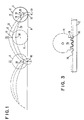
- FIG. 1 shows the basic geometrical concept of the invention.
- circle 6 rolls along flat surface 8
- a point 10 on the circumference of the circle sweeps out an arc 12 in space known as a cycloid which is a particular type of trochoid.
- point 10 is in contact with surface 8.
- circle 6 rotates counter-clockwise.
- Point 10 sweeps out arc 12 reaching a maximum elevation above surface 8 at location 20 of circle 6.
- the center 16 of the circle 6 has traveled a distance equal to one half the circumference of the circle from location 14.
- point 10 returns to a position in contact with surface 8 at position 22 of circle 6.
- the center 16 of the circle 6 has traveled a distance equal to the circumference of the circle from location 14.
- the direction of motion of point 10 at positions 14 and 22 of circle 6 is vertical, that is straight up and down.
- the vertical velocity of point 10 at positions 14, 20 and 22 of circle 6 is zero.
- Point 10 touches surface 8 with no force in positions 14 and 22.
- Point 10 has a maximum acceleration along arc 12 in position 20 of circle 6.
- Point 26 on circle 6 which is along the same radius as point 10 but not on the circumference of circle 6 sweeps out arc 28 when moving from position 14 to position 22.
- Arc 28 is referred to as a curtate trochoid.
- Point 26 does not have a vertically up and down motion, as point 10, in positions 14 and 22 of circle 6.
- point 26 does have zero vertical velocity in positions 14, 20 and 22 of circle 6.
- Point 30 of circle 6 which is along an extension of the radius from center 16 to point 10 on the circumference of circle 6 sweeps out a curve referred to as a prolate trochoid arc 32.
- Arc 32 in positions 14, 20 and 22 of circle 6 has zero vertical velocity, but does not move straight up and down as point 10 does in positions 14 and 22.
- point 30 loops back and forth as shown in FIG. 1.
- Maximum acceleration of point 30 along arc 32 is in position 20 of circle 6.
- the maximum acceleration of point 26 along arc 28 is in position 20 of circle 6.
- arcs or curves 12, 28 and 32 are referred to as trochoids.
- the positions of points 10, 26 and 30 in location 14 and 22 of circle 6 are relative minima.
- the positions of these points in position 20 of circle 6 are relative maxima.
- the maxima and minima location are referred to as extrema.
- a disk-like structure rolls along a planar surface such as 8 of FIG. 1.
- a disk-like structure can roll along a curved surface.
- points 10, 26 and 30 will sweep out continuous smooth curves which for the purpose of this application are included in the term trochoid.
- a workpiece pickup means is positioned to be along the circumference of a disk or cylindrical structure.
- the workpiece pickup means can also be at any point along a radius of the circle 6 of FIG. 1.
- arcs 32 and 28 of FIG. 1 have a continuous first derivative and a continuous second derivative throughout the motion of circle 6.
- Arc 12 has a continuous first and second derivative except in positions 14 and 22 of circle 6 when point 10 is in contact with surface 8. At these locations, arc 12 has a continuous second derivative but a discontinuous first derivative. The first derivative to the right of the point of contact of point 10 with surface 8 is positive infinity. The first derivative just to the left of the point of contact of point 10 with surface 8 is negative infinity. This corresponds to point 10 going vertically up and down at the point of contact of point 10 with surface 8.
- FIG. 2 diagrammatically shows the basic concept of the apparatus according to the present invention.
- Member 40 has a substantially cylindrical surface 42 which rolls along surface 44.
- the pickup arm 47 is formed from member 46 and member 54.
- Member 46 is attached to surface 48 of member 40.
- Member 46 is shown extending perpendicularly from planar surface 48 along axis 50 of cylindrical surface 42.
- pickup arm can be attached to surface 48 of member 40 at any point on surface 40.
- member 40 does not have to have a planar surface 48 and the pickup arm does not have to be perpendicular to such a surface.
- member 54 which extends perpendicularly away from end 52 of member 46.
- End 56 of member 54 in the preferred embodiment is at a distance away from axis 50 of cylindrical surface 42 equal to the radius 58 of cylindrical surface 42.
- pickup arm tip 56 picks up workpiece 60, for example, by a vacuum pickup which is commonly used in the art.
- the axis 50 of cylindrical surface 42 is moved in a direction 64 causing member 40 to roll to position 66.
- Pickup arm tip 56 sweeps an arc 68 in space and member 40 travels a distance L equal to 1/2 the circumference of cylindrical surface 42.
- Pickup arm member 54 rotates 180 degrees with respect to its position at location 62 of member 40 as shown at position 66 of member 40.
- workpiece 60 faces upwardly and can be picked up at this location by a fixture, not shown in FIG. 2, to pickup arm 54.
- the vacuum pickup is released from surface 56 to transfer workpiece 60 to the fixture.
- Member 40 can roll from position 66 to position 69 which is at a distance L′ equal to the circumference of the cylindrical surface 42.
- pickup arm member 54 has made a 360 degree revolution with respect to its location at position 62 of member 40.
- workpiece 60 can be deposited at a fixture not shown in FIG. 2 by the release of the vacuum pickup in pickup arm 54.
- vacuum pickup is the preferred embodiment for the pickup means the apparatus of the present invention is not limited thereto.
- member 40 rolls from position 66 to position 69 workpiece 60 travels through a trochoid arc in space.
- the pickup arm can pick up and release the workpiece at any point along arc 68.
- FIG. 3 shows the preferred embodiment of member 40 and surface 44 of FIG. 2.
- Member 40 of FIG. 2 is shown as spur or pinion gear 70.
- Surface 44 of FIG. 2 is shown in FIG. 3 as rack gear 72.
- Dashed line 74 along the perimeter of pinion gear 70 corresponds to the surface 42 of FIG. 2, that is, the cylindrical surface which rolls.
- Surface 74 is approximately at the mid-point between the peak and valley of the gear teeth of pinion gear 70.
- Surface 74 is known in the art as the pitch diameter.
- Surface 74 rolls along surface 76 of rack gear 72.
- Surface 76 is approximately midway between the peak and valley of the teeth of rack gear 72.
- the teeth 78 of pinion gear 70 mesh with the teeth 80 of rack gear. Even in the most ideal situations, there is a certain amount of free play or slop between the gear teeth on the pinion gear and the rack gear. As will be described herein and below, this slop is accounted for in the preferred embodiment of the present invention.
- the preferred embodiment of the apparatus according to the present invention has a base plate 90 on which is mounted a commercially available e.g. model NSR20TBA1UU-340, manufactured by THK Inc. linear slide having stationary track 92 and movable carriage 94.
- a suitable bearing block 96 which a person of skill in the art can readily fabricate, is bolted to carriage 94.
- Bearing block 96 has affixed to it on opposite faces bearings 98 and 100.
- a rotatable shaft 102 is affixed through bearing block 96 and through bearings 98 and 100 permitting shaft 102 to rotate with respect to bearing block 96.
- shaft 102 At one end of shaft 102 is spur gear or pinion gear 104, that meshes with a stationary rack gear 106.
- the rack and pinion gears are commercially available, e.g. part numbers AG31 and DG80T60, manufactured by PIC DESIGN Corp.
- arm 107 On the other end of rotatable shaft 102 is affixed an arm 107.
- Arm 107 is formed from a first member 108 having a first 109 end of which is attached in a perpendicular configuration with respect to rotatable shaft 102.
- Arm 107 has a second member 110 projecting from the opposite end 111 of arm 108 in a perpendicular direction away from bearing block 96.
- Arm 107 has a third member 112 which is attached at one end to arm member 108 near the connection of arm member 108 to rotable shaft 102.
- the second end of arm member 112 is connected to arm member 110 near the end of arm member 110.
- Arm member 112 provides structural support for the attachment of arm member 108 to arm member 110.
- At end 114 of arm member 110 there is a pickup tip 116.
- pickup tip 116 extends in a perpendicular direction away from pickup arm 106 and 114.
- Pickup tip 116 has a cavity therein which extends to pickup surface 120.
- the hose not shown in the figures connects fitting 122 to fitting 124 which is at the end of rotatable shaft 102 which projects through arm member 108 of pickup arm 106.
- Fitting 126 is on the end of shaft 102 which projects through spur gear 104.
- a vacuum hose is applied to fitting 126. Vacuum is supplied through hollow rotatable shaft 102 through fitting 124 through the hose connecting fitting 124 and 122. The vacuum is then applied through cavity 118 to an aperture on surface 120 which is used to pickup a workpiece.
- the vacuum supplied to surface 120 is turned on and off by use of a commonly used solenoid valve, for example, part number R481 manufactured by CLIPPARD MFG. Co.
- Movable carriage 94 is moved from a first to a second position along slide track 92 by pneumatic cylinder 130.
- Pneumatic cylinders are commonly used in the art, for example, part number MRS-048-DXP manufactured by BIMBA MFG. Corp.
- the workpiece picked up is a integrated circuit chip.
- Pneumatic cylinder 130 moves carriage 94 from a first position in which pickup tip 116 picks up thc IC chip and then pneumatic cylinder 130 moves carriage 94 to a second positon where pickup tip 116 deposits the chip by releasing the vacuum at surface 120.
- spur gear or pinion gear 104 rotates because it meshes with stationary rack gear 106.
- Shaft 102 attached to spur gear 104 rotates arm 107 which is attached to shaft 102.
- Picked up chip travels through space in a trochoid arc as described herein and above.
- Pneumatic cylinder 130 controlled by a second solenoid valve which controls the flow of a gas such as air into and out of the pneumatic cylinder to control the movement thereof.
- the solenoid valve controlling the movement of pneumatic cylinder 130 and controlling the vacuum pickup at pickup arm end 116 can be synchronized and controlled by a computer or other device in a manner commonly known in the art.
- pneumatic cylinder 130 moves carriage 94 from a first position 140 to a second position 142 shown in phantom in FIG. 7.
- shock absorber 144 At position 140 and 142, its motion is slowed down by shock absorber 144 at position 140 and shock absorber 146 at position 142.
- Shock absorbers 144 and 146 are commercially available, for example, part number OEM5B manufactured by ENIDINE.
- tip 145 of shock absorber 144 presses against member 160 which is attached to carriage 94.
- member 162 is pressed against tip 147 of shock absorber 146.
- Shock absorbers 144 and 146 are attached to base plate 90 and number 158, respectively, through respective fixtures 143 and 141.
- End 164 of pneumatic cylinder 130 is attached to carriage 94 and end 166 of pneumatic cylinder is attached to pivot bracket 168 which is attached to base plate 90.
- FIG. 7 shows a side plan view of the apparatus of FIG. 4 in a direction indicated by arrow B in FIG. 4.
- FIG. 7 shows pinion 104 in a first position 140 and in a second position 142.
- Position 142 is shown in phantom.
- all elements, e.g. shock absorbers 146 and 144, shown in FIG. 4 are not shown in FIG. 7.
- Pinion 104 and rack 106 are not shown with gear teeth. When pin 148 is pushed against stop 152 or 154, the gear teeth of the spur gear are pushed against the teeth of the rack gear 106, thereby avoiding any uncertainty in the position of the spur gear due to slop between the spur and rack gear teeth.
- FIG. 8 shows a side view of the apparatus of FIG. 4 in a direction indicated by arrow C. All elements in FIG. 4 are not shown in FIG. 8 for the sake of clarity.
- pickup arm tip 116 is facing down.
- an electronic device 180 is picked up.
- the vacuum is activated by a solenoid valve not shown.
- Another solenoid valve activates pneumatic cylinder 130 to push carriage 94 along track 92 to position 142.
- the position of pickup arm 106 is shown in phantom in positions 182, 184, 186, 188, 189, 190 and 192. It shows the pickup arm twisting in space, changing the orientation of electronic device 180.
- the electronic device is flipped into a face up position in position 188 of pickup arm 106.
- the electronic device is flipped over again in position 192.
- the electronic device or any other workpiece can be picked up at any point along transit path of the pickup arm.
- the electronic device can be deposited at any location along the transit path of the pickup arm.
- an electronic device will be picked up from a storage location holding the chips face up.
- Pickup arm picks the chip up and typically would stop at a position such as 180 to deposit the chip onto another apparatus such as a bondhead of a bonding tool. Vacuum in the bondhead tip 116 is released and a vacuum pickup would be activated in the bondhead picking the chip up.
- Another typical position in which the chip would be transported is that shown in location 194, wherein the chip is deposited in a face down configuration, for example, on a bondhead.
- FIG. 9 diagrammatically shows the preferred orientation of the pickup arm 107 with respect to the center 200 of the member 202 having a cylindrical surface 204.
- the member having the cylindrical surface is the pinion or spur gear 104 and the cylindrical surface is the pitch diameter of the spur gear.
- the surface 206 of pickup arm 107 which picks up workpiece 208 from surface 210 has a forward edge 212 which is along a radius of cylindrical surface 204 to the point where forward edge 212 touches surface 210.
- trailing edge 214 of surface 206 is lifted first off of surface 210.
- Workpiece 208 instantaneously rotates about point 213 which is the point of contact of forward edge 212 with surface 210.
- edge 125 of pickup arm 107 is along the axis of rotatable shaft 102.
- FIG. 10 diagrammatically shows the apparatus of the present invention used in an electronic device bonding tool.
- Pickup arm 107 extends out from housing 220 which contains most of the elements of the apparatus shown in FIG. 4. Numbers common between FIG. 4 and FIG. 10 represent the same thing.
- Pickup arm tip 116 picks up an electronic device 222 from an array of devices on a table 224 which is movable in an X and Y direction.
- table 224 orients one of the chips 222 under the pickup arm end 216. Vacuum is activated in pickup arm end 116 by a solenoid valve and gas pressure is activated in pneumatic cylinder 130.
- pickup arm 107 advances one-half the circumference of pitch diameter of pinion gear 104, the chip will be in an upwardly facing orientation and can be picked up by a vacuum pickup port 226 shown in phantom in bondhead 228. If pickup arm 107 advances a distance equivalent to the circumference of the pitch diameter of spur gear 104, the chip can be deposited onto surface 230 of bondhead 232. Multiple chip placements can be achieved by using more than one apparatus as shown in FIG. 4. In the situation where the electronic device position is only going to be inverted or where the spur gear advances only one-half the circumference of the pitch diamter, only a semi-circular spur gear 104 need be used. When a semi-circular spur gear is used, pin 148 as shown in FIG. 4 need not be used. Instead an edge along the diameter of the semi-circular spur gear can be pushed up against adjustable stops 154 and 152.
Landscapes
- Engineering & Computer Science (AREA)
- Microelectronics & Electronic Packaging (AREA)
- Condensed Matter Physics & Semiconductors (AREA)
- General Physics & Mathematics (AREA)
- Manufacturing & Machinery (AREA)
- Computer Hardware Design (AREA)
- Physics & Mathematics (AREA)
- Power Engineering (AREA)
- Specific Conveyance Elements (AREA)
- Feeding Of Workpieces (AREA)
- Manipulator (AREA)
- Automatic Assembly (AREA)
- Container, Conveyance, Adherence, Positioning, Of Wafer (AREA)
Abstract
Description
- This invention relates to a workpiece transfer device, more particularly, a device for transferring an integrated circuit electronic device from a first position to a second position for use in an apparatus for bonding the electronic device to electrically conductive elements.
- Transferring parts or workpieces in an automatic assembly machine generally requires three motions: a vertical upward motion to lift the part out of a storage device such as a hopper or magazine, a horizontal motion to move the part to another location on the machine, and another vertical but downward motion to place the part into an assembly or another station on the machine that does subsequent operations on the part. There are two independent directions of motion, a vertical motion and a horizontal motion. These two motions necessitate a control device to control the two independent motions and to sequence them properly in an automated machine. The sequencing operation very often necessitates sensing devices during the transfer to insure one of the three motions has taken place and is completed before the subsequent motion is initiated.
- Thus the invention as claimed is intended to remedy these drawbacks. The invention solves the problem of reducing the time and the computer controlled operations for the transfer of a workpiece from a first to a second location.
- In its broadest aspect this invention is an apparatus for transferring a workpiece from a first predetermined location to a second predetermined location through a substantially continuously curved arc from the first location to the second location.
- In a more particular aspect of this invention, the apparatus has a frame, a surface on the frame, a member having a substantially cylindrical surface which is adapted for rolling along the surface. There is a workpiece pickup means attached to the member. There is a means for causing the cylindrical surface to roll along the surface on the frame. This causes the pickup means to move along a curved arc from the first location to the second location.
- In another more particular aspect of the present invention, the member with the substantially cylindrical surface is a spur on pinion gear and the surface along which it rolls on the frame is a rack gear.
- In another more particular aspect of the present invention, the workpiece pickup means is an arm which projects outwardly from the plane of the spur gear, the pickup point on the arm being located at a distance from the axis of the spur gear substantially equal to the radius of the spur gear.
- In another more particular aspect of the present invention, there is a vacuum pickup means at the tip of the workpiece pickup means.
- In another more particular aspect of the present invention, one edge of the workpiece pickup means tip is at the intersection of the radius of the spur gear and the surface defined by the pitch diameter of the spur gear.
- The device described herein uses only one motion to accomplish this tranfer. The need for three motions is eliminated by using a single curved motion that approximates an upward, then horizontal, then downward motion. The motion is generated kinamaticly using a sliding device and a set of gears. The elimination of one of the two independent motions, vertical and horizontal, of the prior art machines reduces the time for making a transfer of a workpiece from a first location to a second location, thereby increasing the speed of operation. Moreover, since only one motion is needed there is a reduction in the computer controlled operations for the transfer. These combine to reduce the cost and complexity of the workpiece transfer operation. Furthermore, and very significantly, a single motion transfer eliminates all of the complexity of synchronizing the two independent motions, the horizontal and the vertical, of the prior art devices.
- The present invention has been found to be particularly useful for high speed manufacture of integrated circuit electronic components. In particular, the apparatus of the present invention can be used to pick up a semiconductor chip from a storage location and to transfer it to a bondhead which is used to bond contact locations on the semiconductor chip to the plurality of beam leads for electrically connecting the semiconductor chip to an electronic packaging substrate.
- It is an advantage of this invention to provide an apparatus for transferring a workpiece from a first location to a second location along a substantially smooth curved motion.
- It is another advantage of this invention to provide an apparatus to vertically pickup, to horizontally transfer and to vertically deposit a workpiece using one motion.
- It is another advantage of this invention to provide an apparatus to deposit a workpiece at a location with substantially no vertical speed at the deposit location.
- It is another advantage of this invention, transfer a workpiece from a first location to a second location along a trochoid like curve.
- It is another advantage of this invention to achieve the trochoid transfer motion by rolling a cylindrical shaped member along a surface, wherein there is a workpiece pickup arm projecting along a direction parallel to the cylindrical surface.
- These and other objects, features and advantages will be apparent from the following more particular description of the preferred embodiments with reference to the accompanying drawings, in which:
- FIG. 1 shows the geometrical concept on which the present invention is based;
- FIG. 2 diagramatically shows the basic concept of the apparatus according to the present invention;
- FIG. 3 shows a spur or pinion gear mounted to roll along a rack gear;
- FIG. 4 shows a perspective view of the preferred embodiment of the present invention;
- FIG. 5 shows a top plan view of the apparatus of FIG. 4;
- FIG. 6 shows a back plan view of the apparatus of FIG. 4 in the direction indicated by A in FIG. 4;
- FIG. 7 shows a side plan view of the apparatus of FIG. 4 in the direction indicated by B in FIG. 4;
- FIG. 8 is a side plan view of the apparatus of FIG. 4 in the direction indicated as 4 in FIG. 4 indicating various positions of the pickup means of the apparatus of FIG. 4 during transfer from a first to a second position;
- FIG. 9 is a diagrammatic view of the preferred orientation of the pickup arm tip surface with respect to the spur gear if the preferred embodiment of FIG. 4; and
- FIG. 10 diagrammatically shows the apparatus of FIG. 4 as part of a semiconductor chip bonding apparatus.
- FIG. 1 shows the basic geometrical concept of the invention. When circle 6 rolls along flat surface 8, a
point 10 on the circumference of the circle sweeps out anarc 12 in space known as a cycloid which is a particular type of trochoid. Inposition 14 of circle 6,point 10 is in contact with surface 8. As thecenter 16 of circle 6 moves in the direction of 18, circle 6 rotates counter-clockwise.Point 10 sweeps outarc 12 reaching a maximum elevation above surface 8 atlocation 20 of circle 6. Atlocation 20 thecenter 16 of the circle 6 has traveled a distance equal to one half the circumference of the circle fromlocation 14. As circle 6 continues to move in thedirection 18,point 10 returns to a position in contact with surface 8 atposition 22 of circle 6. Atlocation 22 thecenter 16 of the circle 6 has traveled a distance equal to the circumference of the circle fromlocation 14. The direction of motion ofpoint 10 atpositions point 10 atpositions Point 10 touches surface 8 with no force inpositions Point 10 has a maximum acceleration alongarc 12 inposition 20 of circle 6.Point 26 on circle 6 which is along the same radius aspoint 10 but not on the circumference of circle 6 sweeps out arc 28 when moving fromposition 14 toposition 22. Arc 28 is referred to as a curtate trochoid.Point 26 does not have a vertically up and down motion, aspoint 10, inpositions point 26 does have zero vertical velocity inpositions Point 30 of circle 6 which is along an extension of the radius fromcenter 16 topoint 10 on the circumference of circle 6 sweeps out a curve referred to as aprolate trochoid arc 32. Arc 32 inpositions point 10 does inpositions positions point 30 loops back and forth as shown in FIG. 1. Maximum acceleration ofpoint 30 alongarc 32 is inposition 20 of circle 6. The maximum acceleration ofpoint 26 along arc 28 is inposition 20 of circle 6. For the purpose of this application arcs orcurves points location position 20 of circle 6 are relative maxima. The maxima and minima location are referred to as extrema. - In the preferred embodiment of this invention, a disk-like structure rolls along a planar surface such as 8 of FIG. 1. However, this invention is not limited to such motion. A disk-like structure can roll along a curved surface. In this case, points 10, 26 and 30 will sweep out continuous smooth curves which for the purpose of this application are included in the term trochoid. As described below in the preferred embodiment, a workpiece pickup means is positioned to be along the circumference of a disk or cylindrical structure. However, the workpiece pickup means can also be at any point along a radius of the circle 6 of FIG. 1. For a general surface 8, arcs 32 and 28 of FIG. 1 have a continuous first derivative and a continuous second derivative throughout the motion of circle 6.
Arc 12 has a continuous first and second derivative except inpositions point 10 is in contact with surface 8. At these locations,arc 12 has a continuous second derivative but a discontinuous first derivative. The first derivative to the right of the point of contact ofpoint 10 with surface 8 is positive infinity. The first derivative just to the left of the point of contact ofpoint 10 with surface 8 is negative infinity. This corresponds to point 10 going vertically up and down at the point of contact ofpoint 10 with surface 8. - FIG. 2 diagrammatically shows the basic concept of the apparatus according to the present invention.
Member 40 has a substantiallycylindrical surface 42 which rolls alongsurface 44. Thepickup arm 47 is formed frommember 46 andmember 54.Member 46 is attached to surface 48 ofmember 40.Member 46 is shown extending perpendicularly fromplanar surface 48 alongaxis 50 ofcylindrical surface 42. In the preferred embodiment described herein and below pickup arm is attached tomember 40 in this way. However, the pickup arm can be attached to surface 48 ofmember 40 at any point onsurface 40. Moreovermember 40 does not have to have aplanar surface 48 and the pickup arm does not have to be perpendicular to such a surface. - In the preferred embodiment to the
end 52 ofmember 46 which is not attached to surface 48 there ismember 54 which extends perpendicularly away fromend 52 ofmember 46.End 56 ofmember 54 in the preferred embodiment is at a distance away fromaxis 50 ofcylindrical surface 42 equal to theradius 58 ofcylindrical surface 42. Atposition 62 ofmember 40pickup arm tip 56 picks upworkpiece 60, for example, by a vacuum pickup which is commonly used in the art. Theaxis 50 ofcylindrical surface 42 is moved in adirection 64 causingmember 40 to roll toposition 66.Pickup arm tip 56 sweeps anarc 68 in space andmember 40 travels a distance L equal to 1/2 the circumference ofcylindrical surface 42.Pickup arm member 54 rotates 180 degrees with respect to its position atlocation 62 ofmember 40 as shown atposition 66 ofmember 40. Atlocation 66 ofmember 40,workpiece 60 faces upwardly and can be picked up at this location by a fixture, not shown in FIG. 2, topickup arm 54. The vacuum pickup is released fromsurface 56 to transferworkpiece 60 to the fixture.Member 40 can roll fromposition 66 to position 69 which is at a distance L′ equal to the circumference of thecylindrical surface 42. Atlocation 69 ofmember 40pickup arm member 54 has made a 360 degree revolution with respect to its location atposition 62 ofmember 40. Atlocation 69 ofmember 40workpiece 60 can be deposited at a fixture not shown in FIG. 2 by the release of the vacuum pickup inpickup arm 54. Although vacuum pickup is the preferred embodiment for the pickup means the apparatus of the present invention is not limited thereto. Whenmember 40 rolls fromposition 66 to position 69workpiece 60 travels through a trochoid arc in space. The pickup arm can pick up and release the workpiece at any point alongarc 68. - FIG. 3 shows the preferred embodiment of
member 40 andsurface 44 of FIG. 2.Member 40 of FIG. 2 is shown as spur orpinion gear 70.Surface 44 of FIG. 2 is shown in FIG. 3 asrack gear 72. Dashedline 74 along the perimeter ofpinion gear 70 corresponds to thesurface 42 of FIG. 2, that is, the cylindrical surface which rolls.Surface 74 is approximately at the mid-point between the peak and valley of the gear teeth ofpinion gear 70.Surface 74 is known in the art as the pitch diameter.Surface 74 rolls alongsurface 76 ofrack gear 72.Surface 76 is approximately midway between the peak and valley of the teeth ofrack gear 72. Theteeth 78 ofpinion gear 70 mesh with theteeth 80 of rack gear. Even in the most ideal situations, there is a certain amount of free play or slop between the gear teeth on the pinion gear and the rack gear. As will be described herein and below, this slop is accounted for in the preferred embodiment of the present invention. - As shown in FIGS. 4 - 9 the preferred embodiment of the apparatus according to the present invention has a
base plate 90 on which is mounted a commercially available e.g. model NSR20TBA1UU-340, manufactured by THK Inc. linear slide havingstationary track 92 andmovable carriage 94. Asuitable bearing block 96, which a person of skill in the art can readily fabricate, is bolted tocarriage 94.Bearing block 96 has affixed to it onopposite faces bearings rotatable shaft 102 is affixed through bearingblock 96 and throughbearings shaft 102 to rotate with respect to bearingblock 96. At one end ofshaft 102 is spur gear orpinion gear 104, that meshes with astationary rack gear 106. The rack and pinion gears are commercially available, e.g. part numbers AG31 and DG80T60, manufactured by PIC DESIGN Corp. On the other end ofrotatable shaft 102 is affixed anarm 107.Arm 107 is formed from afirst member 108 having a first 109 end of which is attached in a perpendicular configuration with respect torotatable shaft 102.Arm 107 has asecond member 110 projecting from theopposite end 111 ofarm 108 in a perpendicular direction away from bearingblock 96.Arm 107 has athird member 112 which is attached at one end toarm member 108 near the connection ofarm member 108 torotable shaft 102. The second end ofarm member 112 is connected toarm member 110 near the end ofarm member 110.Arm member 112 provides structural support for the attachment ofarm member 108 toarm member 110. Atend 114 ofarm member 110, there is apickup tip 116. In the preferredembodiment pickup tip 116 extends in a perpendicular direction away frompickup arm Pickup tip 116 has a cavity therein which extends topickup surface 120. At the other end ofcavity 118, there is a fitting 122 to which a hose is attached for applying vacuum to thepickup tip 116. The hose not shown in the figures connects fitting 122 to fitting 124 which is at the end ofrotatable shaft 102 which projects througharm member 108 ofpickup arm 106. Fitting 126 is on the end ofshaft 102 which projects throughspur gear 104. A vacuum hose is applied to fitting 126. Vacuum is supplied through hollowrotatable shaft 102 through fitting 124 through the hose connecting fitting 124 and 122. The vacuum is then applied throughcavity 118 to an aperture onsurface 120 which is used to pickup a workpiece. The vacuum supplied to surface 120 is turned on and off by use of a commonly used solenoid valve, for example, part number R481 manufactured by CLIPPARD MFG. Co. -
Movable carriage 94 is moved from a first to a second position alongslide track 92 bypneumatic cylinder 130. Pneumatic cylinders are commonly used in the art, for example, part number MRS-048-DXP manufactured by BIMBA MFG. Corp. In the preferred embodiment the workpiece picked up is a integrated circuit chip.Pneumatic cylinder 130 movescarriage 94 from a first position in whichpickup tip 116 picks up thc IC chip and thenpneumatic cylinder 130 movescarriage 94 to a second positon wherepickup tip 116 deposits the chip by releasing the vacuum atsurface 120. Ascarriage 94 moves from the first to the second position spur gear orpinion gear 104 rotates because it meshes withstationary rack gear 106.Shaft 102 attached to spurgear 104 rotatesarm 107 which is attached toshaft 102. Picked up chip travels through space in a trochoid arc as described herein and above.Pneumatic cylinder 130 controlled by a second solenoid valve which controls the flow of a gas such as air into and out of the pneumatic cylinder to control the movement thereof. The solenoid valve controlling the movement ofpneumatic cylinder 130 and controlling the vacuum pickup atpickup arm end 116 can be synchronized and controlled by a computer or other device in a manner commonly known in the art. - As shown in FIG. 7,
pneumatic cylinder 130 movescarriage 94 from afirst position 140 to asecond position 142 shown in phantom in FIG. 7. Ascarriage 94 approachespositions shock absorber 144 atposition 140 andshock absorber 146 atposition 142.Shock absorbers carriage 94 is inposition 140tip 145 ofshock absorber 144 presses againstmember 160 which is attached tocarriage 94. Whencarriage 94 is inposition 142member 162 is pressed againsttip 147 ofshock absorber 146. - The motion of
carriage 94 is stopped bypin 148 which is pressed fit into an aperture in theside 150 ofspur gear 104.Pin 148 extends perpendicular to surface 150 ofspur gear 104 and is directed towardspickup arm 107. Whencarriage 94 is inposition 140, pin is 148 againstadjustable stop 152. Whencarriage 94 is inposition 142,pin 148 is againstadjustable stop 154.Adjustable stops member base plate 90. -
Shock absorbers base plate 90 andnumber 158, respectively, throughrespective fixtures -
End 164 ofpneumatic cylinder 130 is attached tocarriage 94 and end 166 of pneumatic cylinder is attached to pivotbracket 168 which is attached tobase plate 90. - FIG. 7 shows a side plan view of the apparatus of FIG. 4 in a direction indicated by arrow B in FIG. 4. FIG. 7 shows
pinion 104 in afirst position 140 and in asecond position 142.Position 142 is shown in phantom. For the sake of clarity, all elements,e.g. shock absorbers Pinion 104 andrack 106 are not shown with gear teeth. Whenpin 148 is pushed againststop rack gear 106, thereby avoiding any uncertainty in the position of the spur gear due to slop between the spur and rack gear teeth. - FIG. 8 shows a side view of the apparatus of FIG. 4 in a direction indicated by arrow C. All elements in FIG. 4 are not shown in FIG. 8 for the sake of clarity. When
carriage 94 is inposition 140pickup arm tip 116 is facing down. Upon the application of a vacuum throughaperture 118 inpickup arm end 116 anelectronic device 180 is picked up. The vacuum is activated by a solenoid valve not shown. Another solenoid valve activatespneumatic cylinder 130 to pushcarriage 94 alongtrack 92 toposition 142. In FIG. 8 the position ofpickup arm 106 is shown in phantom inpositions electronic device 180. The electronic device is flipped into a face up position inposition 188 ofpickup arm 106. The electronic device is flipped over again inposition 192. The electronic device or any other workpiece can be picked up at any point along transit path of the pickup arm. Also the electronic device can be deposited at any location along the transit path of the pickup arm. Typically, an electronic device will be picked up from a storage location holding the chips face up. Pickup arm picks the chip up and typically would stop at a position such as 180 to deposit the chip onto another apparatus such as a bondhead of a bonding tool. Vacuum in thebondhead tip 116 is released and a vacuum pickup would be activated in the bondhead picking the chip up. Another typical position in which the chip would be transported is that shown inlocation 194, wherein the chip is deposited in a face down configuration, for example, on a bondhead. - FIG. 9 diagrammatically shows the preferred orientation of the
pickup arm 107 with respect to thecenter 200 of themember 202 having acylindrical surface 204. In the apparatus of FIG. 4, the member having the cylindrical surface is the pinion orspur gear 104 and the cylindrical surface is the pitch diameter of the spur gear. Thesurface 206 ofpickup arm 107 which picks upworkpiece 208 fromsurface 210 has aforward edge 212 which is along a radius ofcylindrical surface 204 to the point whereforward edge 212 touchessurface 210. Asmember 202 rotates aboutcenter 200trailing edge 214 ofsurface 206 is lifted first off ofsurface 210.Workpiece 208 instantaneously rotates aboutpoint 213 which is the point of contact offorward edge 212 withsurface 210. This configuration permitsworkpiece 208 to be peeled off ofsurface 210. If theleading edge 212 were not along a radius from thecenter 200 ofcylindrical surface 202, asmember 202 began to rotate the leading edge would be pushed intosurface 210. Dashed line 119 illustrates thissituation intersecting circle 204 atpoint 113 on radius 115. Dashed line 119 has aleading edge 117 which is not on a radius of the circle. Line 119 is shown in a rotated position withedge 117 belowsurface 210. This can be avoided either by havingworkpiece 206 be picked up bypickup arm 106, for example by a vacuum pickup and then either movingsurface 210 down making room for the leading edge to rotate without touchingsurface 210 or the arrangement diagrammatically shown in FIG. 9 can be used to avoid having to movesurface 210 down. After a full rotation ofbody 202,workpiece 208 is deposited again ontosurface 210.Edge 214touching surface 210 first and thereafter edge 212touching surface 210 without havingworkpiece 208 being pushed intosurface 210. In the top plan view of the preferred embodiment of the invention shown in FIG. 5 it can be seen thatedge 125 ofpickup arm 107 is along the axis ofrotatable shaft 102. - FIG. 10 diagrammatically shows the apparatus of the present invention used in an electronic device bonding tool.
Pickup arm 107 extends out fromhousing 220 which contains most of the elements of the apparatus shown in FIG. 4. Numbers common between FIG. 4 and FIG. 10 represent the same thing.Pickup arm tip 116 picks up anelectronic device 222 from an array of devices on a table 224 which is movable in an X and Y direction. On computer control, table 224 orients one of thechips 222 under the pickup arm end 216. Vacuum is activated inpickup arm end 116 by a solenoid valve and gas pressure is activated inpneumatic cylinder 130. Ifpickup arm 107 advances one-half the circumference of pitch diameter ofpinion gear 104, the chip will be in an upwardly facing orientation and can be picked up by avacuum pickup port 226 shown in phantom inbondhead 228. Ifpickup arm 107 advances a distance equivalent to the circumference of the pitch diameter ofspur gear 104, the chip can be deposited ontosurface 230 ofbondhead 232. Multiple chip placements can be achieved by using more than one apparatus as shown in FIG. 4. In the situation where the electronic device position is only going to be inverted or where the spur gear advances only one-half the circumference of the pitch diamter, only asemi-circular spur gear 104 need be used. When a semi-circular spur gear is used, pin 148 as shown in FIG. 4 need not be used. Instead an edge along the diameter of the semi-circular spur gear can be pushed up againstadjustable stops
Claims (12)
a frame;
a surface on said frame;
a member movably mounted to said surface;
a workpiece pickup means attached to said member; and
means for moving said member on said surface causing said pickup means to travel through a substantially continuously curved arc from said first to said second predetermined location.
providing a workpiece;
transferring said workpiece from a first predetermined location along a trochoid arc to a second predetermined location.
Applications Claiming Priority (2)
| Application Number | Priority Date | Filing Date | Title |
|---|---|---|---|
| US27806388A | 1988-11-30 | 1988-11-30 | |
| US278063 | 1988-11-30 |
Publications (3)
| Publication Number | Publication Date |
|---|---|
| EP0371205A2 true EP0371205A2 (en) | 1990-06-06 |
| EP0371205A3 EP0371205A3 (en) | 1991-05-29 |
| EP0371205B1 EP0371205B1 (en) | 1993-12-15 |
Family
ID=23063539
Family Applications (1)
| Application Number | Title | Priority Date | Filing Date |
|---|---|---|---|
| EP19890115344 Expired - Lifetime EP0371205B1 (en) | 1988-11-30 | 1989-08-19 | Transfer Device |
Country Status (3)
| Country | Link |
|---|---|
| EP (1) | EP0371205B1 (en) |
| JP (1) | JPH0832398B2 (en) |
| DE (1) | DE68911490T2 (en) |
Cited By (4)
| Publication number | Priority date | Publication date | Assignee | Title |
|---|---|---|---|---|
| EP0534765A1 (en) * | 1991-09-25 | 1993-03-31 | Kabushiki Kaisha Toshiba | Parts mounting apparatus |
| EP0534701A1 (en) * | 1991-09-25 | 1993-03-31 | Kabushiki Kaisha Toshiba | Parts mounting apparatus |
| EP0534453A1 (en) * | 1991-09-25 | 1993-03-31 | Japan Tobacco Inc. | Method and apparatus for carrying workpiece in a continuous operation |
| CN109733224A (en) * | 2019-03-08 | 2019-05-10 | 重庆陈氏清洁服务有限公司 | Vehicle dynamic traveling current collector with arc-suppression function |
Families Citing this family (1)
| Publication number | Priority date | Publication date | Assignee | Title |
|---|---|---|---|---|
| CN106395309B (en) * | 2016-11-07 | 2018-09-21 | 洪娇娇 | A kind of lossless conveying device of ammeter negative pressure |
Citations (3)
| Publication number | Priority date | Publication date | Assignee | Title |
|---|---|---|---|---|
| FR2125307A1 (en) * | 1971-02-19 | 1972-09-29 | Enzinger Union Werke Ag | |
| US4556362A (en) * | 1983-12-21 | 1985-12-03 | At&T Technologies, Inc. | Methods of and apparatus for handling semiconductor devices |
| WO1987006561A1 (en) * | 1986-04-28 | 1987-11-05 | Varian Associates, Inc. | Modular semiconductor wafer transport and processing system |
Family Cites Families (2)
| Publication number | Priority date | Publication date | Assignee | Title |
|---|---|---|---|---|
| JPS499869A (en) * | 1972-04-22 | 1974-01-28 | ||
| JPS5634538A (en) * | 1979-08-31 | 1981-04-06 | Nissan Motor Co Ltd | Device for transmitting voice information in automobile |
-
1989
- 1989-08-19 EP EP19890115344 patent/EP0371205B1/en not_active Expired - Lifetime
- 1989-08-19 DE DE1989611490 patent/DE68911490T2/en not_active Expired - Fee Related
- 1989-10-25 JP JP1276177A patent/JPH0832398B2/en not_active Expired - Lifetime
Patent Citations (3)
| Publication number | Priority date | Publication date | Assignee | Title |
|---|---|---|---|---|
| FR2125307A1 (en) * | 1971-02-19 | 1972-09-29 | Enzinger Union Werke Ag | |
| US4556362A (en) * | 1983-12-21 | 1985-12-03 | At&T Technologies, Inc. | Methods of and apparatus for handling semiconductor devices |
| WO1987006561A1 (en) * | 1986-04-28 | 1987-11-05 | Varian Associates, Inc. | Modular semiconductor wafer transport and processing system |
Cited By (7)
| Publication number | Priority date | Publication date | Assignee | Title |
|---|---|---|---|---|
| EP0534765A1 (en) * | 1991-09-25 | 1993-03-31 | Kabushiki Kaisha Toshiba | Parts mounting apparatus |
| EP0534701A1 (en) * | 1991-09-25 | 1993-03-31 | Kabushiki Kaisha Toshiba | Parts mounting apparatus |
| EP0534453A1 (en) * | 1991-09-25 | 1993-03-31 | Japan Tobacco Inc. | Method and apparatus for carrying workpiece in a continuous operation |
| US5285888A (en) * | 1991-09-25 | 1994-02-15 | Kabushiki Kaisha Toshiba | Parts mounting apparatus |
| US5417542A (en) * | 1991-09-25 | 1995-05-23 | Japan Tobacco | Method and apparatus for carrying workpiece by continuous workpiece carrying operation |
| CN109733224A (en) * | 2019-03-08 | 2019-05-10 | 重庆陈氏清洁服务有限公司 | Vehicle dynamic traveling current collector with arc-suppression function |
| CN109733224B (en) * | 2019-03-08 | 2023-08-25 | 重庆陈氏清洁服务有限公司 | Dynamic running current collector with arc extinguishing function for vehicle |
Also Published As
| Publication number | Publication date |
|---|---|
| EP0371205B1 (en) | 1993-12-15 |
| DE68911490D1 (en) | 1994-01-27 |
| EP0371205A3 (en) | 1991-05-29 |
| JPH0832398B2 (en) | 1996-03-29 |
| JPH02204220A (en) | 1990-08-14 |
| DE68911490T2 (en) | 1994-06-23 |
Similar Documents
| Publication | Publication Date | Title |
|---|---|---|
| US5102290A (en) | Transfer device | |
| US5195235A (en) | Parts mounting apparatus | |
| EP3503220A2 (en) | Device and method for turning cell over | |
| US4450950A (en) | Work piece transfer mechanism | |
| JPH08195589A (en) | Electronic part mounting device | |
| EP0371205A2 (en) | Transfer Device | |
| US5649804A (en) | Pick and place machine | |
| CN117735247A (en) | Turnover material arranging machine | |
| JP3200326B2 (en) | Transfer method and transfer device for disk-shaped workpiece | |
| US5056844A (en) | Multiple jaw centering head structure for surface mounted component placement machines | |
| US4843712A (en) | Method and apparatus for handling parts | |
| JPH0748018A (en) | Article detector for article transfer device | |
| CN212558256U (en) | Online upright turning device | |
| CN215469827U (en) | Automatic part taking equipment for high-speed machining of valve body parts | |
| JPH0748027A (en) | Article transferring device | |
| JP2617249B2 (en) | Supply device of semiconductor chip to lead frame | |
| JP3354238B2 (en) | Article transfer equipment | |
| CN221102048U (en) | Get and put mechanism, wafer conveyer and cleaning equipment | |
| US3581911A (en) | Die-positioning mechanism | |
| CN112349636A (en) | High-precision large-board-level micro-assembly equipment | |
| CN212580953U (en) | Feeding equipment for burning machine | |
| JPS6071435A (en) | Film take-out device in film exchanger for x-ray apparatus | |
| TWI658967B (en) | Automatic high speed filling machine | |
| JPH0323453B2 (en) | ||
| JPH0427699B2 (en) |
Legal Events
| Date | Code | Title | Description |
|---|---|---|---|
| PUAI | Public reference made under article 153(3) epc to a published international application that has entered the european phase |
Free format text: ORIGINAL CODE: 0009012 |
|
| AK | Designated contracting states |
Kind code of ref document: A2 Designated state(s): DE FR GB |
|
| 17P | Request for examination filed |
Effective date: 19900926 |
|
| PUAL | Search report despatched |
Free format text: ORIGINAL CODE: 0009013 |
|
| AK | Designated contracting states |
Kind code of ref document: A3 Designated state(s): DE FR GB |
|
| 17Q | First examination report despatched |
Effective date: 19911106 |
|
| GRAA | (expected) grant |
Free format text: ORIGINAL CODE: 0009210 |
|
| AK | Designated contracting states |
Kind code of ref document: B1 Designated state(s): DE FR GB |
|
| REF | Corresponds to: |
Ref document number: 68911490 Country of ref document: DE Date of ref document: 19940127 |
|
| ET | Fr: translation filed | ||
| PLBE | No opposition filed within time limit |
Free format text: ORIGINAL CODE: 0009261 |
|
| STAA | Information on the status of an ep patent application or granted ep patent |
Free format text: STATUS: NO OPPOSITION FILED WITHIN TIME LIMIT |
|
| 26N | No opposition filed | ||
| PGFP | Annual fee paid to national office [announced via postgrant information from national office to epo] |
Ref country code: GB Payment date: 19950726 Year of fee payment: 7 |
|
| PGFP | Annual fee paid to national office [announced via postgrant information from national office to epo] |
Ref country code: FR Payment date: 19950807 Year of fee payment: 7 |
|
| PGFP | Annual fee paid to national office [announced via postgrant information from national office to epo] |
Ref country code: DE Payment date: 19950821 Year of fee payment: 7 |
|
| PG25 | Lapsed in a contracting state [announced via postgrant information from national office to epo] |
Ref country code: GB Effective date: 19960819 |
|
| GBPC | Gb: european patent ceased through non-payment of renewal fee |
Effective date: 19960819 |
|
| PG25 | Lapsed in a contracting state [announced via postgrant information from national office to epo] |
Ref country code: FR Effective date: 19970430 |
|
| PG25 | Lapsed in a contracting state [announced via postgrant information from national office to epo] |
Ref country code: DE Effective date: 19970501 |
|
| REG | Reference to a national code |
Ref country code: FR Ref legal event code: ST |