EP0371159A1 - Electropneumatical remote control for gear shifting, especially for shifting a synchronized mechanical transmission of motor vehicles - Google Patents
Electropneumatical remote control for gear shifting, especially for shifting a synchronized mechanical transmission of motor vehicles Download PDFInfo
- Publication number
- EP0371159A1 EP0371159A1 EP88119837A EP88119837A EP0371159A1 EP 0371159 A1 EP0371159 A1 EP 0371159A1 EP 88119837 A EP88119837 A EP 88119837A EP 88119837 A EP88119837 A EP 88119837A EP 0371159 A1 EP0371159 A1 EP 0371159A1
- Authority
- EP
- European Patent Office
- Prior art keywords
- remote control
- switching
- unit
- cylinder
- signal
- Prior art date
- Legal status (The legal status is an assumption and is not a legal conclusion. Google has not performed a legal analysis and makes no representation as to the accuracy of the status listed.)
- Withdrawn
Links
Images


Classifications
-
- F—MECHANICAL ENGINEERING; LIGHTING; HEATING; WEAPONS; BLASTING
- F16—ENGINEERING ELEMENTS AND UNITS; GENERAL MEASURES FOR PRODUCING AND MAINTAINING EFFECTIVE FUNCTIONING OF MACHINES OR INSTALLATIONS; THERMAL INSULATION IN GENERAL
- F16H—GEARING
- F16H59/00—Control inputs to control units of change-speed-, or reversing-gearings for conveying rotary motion
- F16H59/02—Selector apparatus
- F16H59/04—Ratio selector apparatus
- F16H59/044—Ratio selector apparatus consisting of electrical switches or sensors
-
- F—MECHANICAL ENGINEERING; LIGHTING; HEATING; WEAPONS; BLASTING
- F16—ENGINEERING ELEMENTS AND UNITS; GENERAL MEASURES FOR PRODUCING AND MAINTAINING EFFECTIVE FUNCTIONING OF MACHINES OR INSTALLATIONS; THERMAL INSULATION IN GENERAL
- F16H—GEARING
- F16H61/00—Control functions within control units of change-speed- or reversing-gearings for conveying rotary motion ; Control of exclusively fluid gearing, friction gearing, gearings with endless flexible members or other particular types of gearing
- F16H61/26—Generation or transmission of movements for final actuating mechanisms
- F16H61/28—Generation or transmission of movements for final actuating mechanisms with at least one movement of the final actuating mechanism being caused by a non-mechanical force, e.g. power-assisted
- F16H61/2807—Generation or transmission of movements for final actuating mechanisms with at least one movement of the final actuating mechanism being caused by a non-mechanical force, e.g. power-assisted using electric control signals for shift actuators, e.g. electro-hydraulic control therefor
-
- F—MECHANICAL ENGINEERING; LIGHTING; HEATING; WEAPONS; BLASTING
- F16—ENGINEERING ELEMENTS AND UNITS; GENERAL MEASURES FOR PRODUCING AND MAINTAINING EFFECTIVE FUNCTIONING OF MACHINES OR INSTALLATIONS; THERMAL INSULATION IN GENERAL
- F16H—GEARING
- F16H61/00—Control functions within control units of change-speed- or reversing-gearings for conveying rotary motion ; Control of exclusively fluid gearing, friction gearing, gearings with endless flexible members or other particular types of gearing
- F16H61/26—Generation or transmission of movements for final actuating mechanisms
- F16H61/28—Generation or transmission of movements for final actuating mechanisms with at least one movement of the final actuating mechanism being caused by a non-mechanical force, e.g. power-assisted
- F16H61/30—Hydraulic or pneumatic motors or related fluid control means therefor
- F16H2061/307—Actuators with three or more defined positions, e.g. three position servos
Definitions
- the invention relates to a remote switching device, by means of which the vehicle driver - with the illusion of manual operation of the traditional shift lever - is able to carry out the shifting of the gear stages with the synchronized mechanical change gear arranged remotely.
- Hydraulic and pneumatic systems have been developed to solve the problem.
- the essence of the hydraulic systems is that the vehicle driver moves pistons in mutually perpendicular cylinders with the aid of the shift lever, and the pistons of the working cylinders connected to the step change element of the change gear are actuated by the hydraulic fluid expressed in this way from the cylinders.
- Such solutions are known from DE-OS 25 10 392, DE-OS 27 00 837, DE-OS 29 35 377 and HU-PS 192.487.
- the hydraulic systems are therefore based on the principle of direct power transmission, and so the vehicle driver has to exert a relatively large force due to the fluid friction over longer distances.
- the step changer of the change gearbox is connected to the piston rod of the shift cylinder or selector cylinder arranged in the switching direction and selection direction.
- the shift cylinder and the selection cylinder are connected to the compressed air system of the motor vehicle by valves. The vehicle The driver treats these valves mechanically or through electrical control.
- the vehicle driver is only supposed to press the switch buttons for electrical control or pull a control arm, which is common in automatic change gearboxes. If such systems are simple, they are inaccurate, there are numerous possible errors for the vehicle driver, and the change gearbox also dies prematurely. The better, more reliable, gentler systems, on the other hand, are very complicated. For this reason, the development has shifted against systems of this type, which simulate the operation of the traditional shift lever to any extent.
- a remote control unit of this type is installed in addition to the vehicle driver, the remote control lever of which is moved by the vehicle driver in accordance with the traditional circuit diagram.
- the remote control lever actuates an electrical switch in its position corresponding to each gear stage, and these switches switch on the electromagnet of those valves which control the pneumatic switching cylinder and selector cylinder which moves the stage changing element.
- This system does not inform the vehicle driver of the course of the gear shift, the end of this course is signaled by a signal lamp. Since the pneumatic working cylinders work too hard, throttle valves are installed in front of them, but also they are only recommended for change gearboxes that are connected to the engine by a hydrodynamic torque converter.
- the remote control unit recognizable from DE-OS 31 38 827 can be used in essentially such systems. Instead of electrical switches, magnets and sensors of an appropriate number are arranged here, in such a way that the individual positions of the remote control lever correspond to a given signal combination.
- the remote control unit described in US Pat. No. 4,646,582 has a similar objective. This is safer than the previous solution because it is fixed in its respective set position by means of a spring-loaded ball orienter, and has a pneumatically actuated construction that keeps the remote control lever in the middle position until the conditions for the step change of the gearbox are not in the step change element are fulfilled.
- the possibility of error for the vehicle driver is well excluded and the actuation of the stage change element is carried out more gently by the remote switching device according to US Pat. No. 4,516,669.
- the gear stage can only be engaged when the gearbox is in the disengaged state and the gearbox can only be closed if the gearbox has been terminated regularly.
- the remote switching devices still meet several conditions today, but they cannot be considered complete. It is known that the gear stage is engaged in two steps in synchronized change gearboxes. The synchronous construction only occurs and the actual switching takes place only after the synchronization. The synchronization requires less, the shift more power. The vehicle driver feels these two steps on the traditional gear lever. This is the most important condition for gentle step switching, and that is exactly what is lacking in previous solutions.
- the aim of our invention is therefore to provide an electropneumatic remote switching device which ensures the shift lever treatment of the change gear complex vehicle driver fully simulated, and for the vehicle driver the course of the tap change fully simulated.
- Our invention is based on the knowledge that with the aid of a corresponding pneumatic working cylinder or corresponding pneumatic fittings, the force of two sizes required during the stepping can be achieved.
- the movement of the remote control lever can be regulated with the help of signal transmitters of the appropriate number and a brake mounting structure with regard to the amount of movement and the force required for movement, in the same way as the traditional shift lever moves.
- the invention therefore relates to an electropneumatic remote switching device, in particular for switching the gear stages of the synchronized mechanical change gear of motor vehicles, with the step change organ of the change gear a pneumatic selection cylinder arranged in the direction of selection with a number of positions corresponding to the number of switch routes and one arranged in the direction of switching, over three Positions of the shift cylinder in operation are connected, and the selection cylinder and the shift cylinder are connected to the compressed air source by means of valves actuated by electromagnets.
- the electro-pneumatic remote control device has a remote control unit operated by the vehicle driver with a remote control lever with positions corresponding to the circuit diagram of the change gearbox, which with in election direction and Switching direction arranged signal transmitters is in the actuating connection, and these are connected by a control unit to the valves actuated by electromagnet.
- the device can be characterized in that the shift cylinder has a lower and a larger pressure force level in its outer positions; that as many signal transmitters are arranged in the remote switching unit in the direction of selection as the number of switching routes; that in the switching direction, at least in comparison to the middle position, two signal transmitters are arranged symmetrically, of which the signal transmitters closer to the middle position are in control connection with valves that produce lower pressure force levels in the outer positions of the shift cylinder, and the signal transmitters further away from the middle position are also in the outer one Position of the switching cylinder in the control connection for larger pressure force stage; that the switching cylinder has at least one signal transmitter which signals the end position; that in the remote control unit the remote control lever is positively connected to a brake mounting structure actuated by auxiliary power, and to the brake mounting structure the signal transmitters arranged in the switching direction in the remote control unit and the signal transmitter signaling the end position of the switching cylinder are in control connection.
- the signal transmitters arranged in the remote control unit in the switching direction are openings, expediently gaps, which are formed in a signal transmitter unit which is connected to the remote control lever in operation, and the movement paths of the openings, expedient gaps, coincide and are in this movement path
- At least one sensor, which generates electrical signals to light is arranged in front of the openings, the field of view of the sensors is expediently displaced by 0.5-1 times the field of view compared to one another, with the remote control lever another signal transmitter unit is in actuation connection, in which a single one Opening, expediently formed column, in front of which is arranged a sensor generating electrical signals in the middle position of the switching lever on the light effect.
- the signal transmitter unit which is connected to the remote control lever and is designed with a plurality of openings, and the signal transmitter unit with an opening are made in one piece, and the path of movement of this last-mentioned single opening falls outside the path of movement of the other openings.
- a third preferred embodiment of the device according to the invention is designed in such a way that the signal transmitter unit which is actuated by the locking lever is at least as long as the distance between the two outer positions, it is provided with openings along its entire length, the width of which corresponds to the width of the sensor's field of view and the division of which is twice the sensor's field of view, and the two sensors arranged in the path of movement of these openings have one , Counting task performing subunit of the control unit in a signal-transmitting connection.
- the brake mounting structure of the remote control unit consists of a loop that is in positive connection with the remote control lever in the switching direction, furthermore of the electromagnet with a line of action perpendicular to the friction surface of the loop, or of a pneumatic working cylinder or hydraulic working cylinder, and that the electromagnet, the pneumatic working cylinder or the hydraulic working cylinder on the friction surface of the loop is less than the force exerted by the hand force exerted on the loop on the remote control lever.
- two abutment surfaces are formed on the loop of the brake mounting structure of the remote control unit, between which the remote control lever or the stop connected to it is arranged, and the distance between the abutment surfaces is greater than the dimension of the remote control lever or the attack between the kick-off surfaces, the remote control lever or the stop is supported in the direction of the abutting surfaces with two springs of the same spring force on the loop.
- a sixth preferred embodiment of the device according to the invention is designed in such a way that the active piston surfaces which bring about the central position of the shift cylinder are smaller than the active piston surfaces which bring about the outer position.
- a pressure reducer is arranged between the valve which supplies the cylinder space which brings about the central position of the shift cylinder with compressed air and the compressed air source.
- each cylinder space of the shift cylinder is connected to the compressed air source in the middle position.
- a further preferred embodiment of the device according to the invention is designed in such a way that the piston rod of the shift cylinder is positively connected to a signal transmitter which has three distances in its direction of movement, and the height of the middle distance differs from the height of the other two distances from the three distances , Furthermore, a sensor is arranged in the signal transmitter and in at least one outer position of the switching cylinder there is an outer distance of the signal transmitter in front of the sensor.
- the device according to the invention is designed in such a way that a signal transmitter is assigned to each position of the selection cylinder, and from these signal transmitters mentioned above and from the signal transmitters arranged in the remote switching unit in the direction of selection, the signal transmitters belonging to the same switching path are connected to one another in a connection which allows the gear stage to be switched.
- Fig. 1 the units of the remote switching device of the change gear are shown.
- This remote switching device was designed for remote switching of such a change gear 11, which is a synchronized mechanical change gear with six forward and one step down in terms of its structure.
- the step change unit 9 is constructed on the change gear 11 and is connected to the remote control unit 7 by the control unit 10.
- the clutch pedal 8 is also connected to these units - in the manner shown in FIG. 1. We will describe the role of the clutch pedal later, but we have to emphasize now that it is not indispensable for realizing the invention.
- the remote control unit 7 can be seen in greater detail on the basis of FIGS. 2 to 6.
- the remote control lever 12 - which fulfills the function of the normal shift lever - can be rotated according to the circuit diagram 52 in Fig. 4 in the housing 13 of the remote control unit using a ball joint 14.
- the circuit diagram 52 is of the usual double H-shape, with the switching routes 1-2 x , 3-4 x , 5-6 x and R x corresponding to the switching of the gear stages.
- the remote control lever position corresponding to gear stages 1 and 2 In the two ends of the switching street 1-2 times is the remote control lever position corresponding to gear stages 1 and 2, in the two ends of shift line 3-4 x is the remote control lever position corresponding to gear stages 3 and 4, in the two ends of switching line 5-6 x is the remote control lever position corresponding to gear stages 5 and 6, and in the shifting street R x is the remote control lever position corresponding to the drop stage R.
- the neutral position N is 3-4 times for the switchgear.
- the control unit 10 is informed of the respective position of the remote control lever 12 by signal transmitters.
- the switching route is 1-2 x corresponding to the sensor EV12, the switching route 3-4 x corresponding to the sensor EV34, the switching route 5-6 x corresponding to the sensor EV56, and finally the switching route R x corresponding to the sensor EVR in the lower part of the housing 13 is arranged in the plane of movement of the remote control lever 12 in the direction of selection v .
- the sensors EV12, EV34, EV56 and EVR are inductive sensors.
- an arcuate plate 15 is attached, which always covers any of the sensors even when the remote control lever 12 moves in the switching direction k .
- the sensors EV12, EV34, EV56 and EVR are the signal transmitters which, in reality, generate the necessary signal together with the plate 15.
- the signaling of the position of the remote control lever 12 in the switching direction k is a more complex task, so this construction is more complicated.
- a link 16 is shown on the part between the ball joint 14 and the plate 15 such that it can be displaced in the switching direction k .
- a line 17 is formed in the backdrop 16, in which the remote control lever 12 can move freely in the direction of selection v , but not in the switching direction k .
- a signal transmitter unit 18 is attached, which is shown on a larger scale in FIG. 5. This is actually a plate whose plane is parallel to the movement in the switching direction k and whose longer edges fall in the switching direction k . Twenty-one pieces of columns 20 of the same width s are cut in one longitudinal edge with a division o . The division o is twice the width s . These columns 20 are provided in FIG. 5 with row numbers +1 to +10 and -1 to -10, respectively, for easy understanding to the right and left of the middle row number 0. The movement path p 1 of these columns 20 coincide with the movement in the switching direction k and are also parallel to it. The length l of the part of the signal transmitter unit 18 provided with the columns 20 is identical to the distance L between the two outer positions of the signal transmitter unit 18.
- a single column 19 of width s is formed in the other longitudinal edge of the signal generator unit 18. Their trajectory p 2 falls outside the trajectory p 1, but is apparently parallel to it.
- the EK0, EK1 and EK2 sensors are used to sense the load movement of the signal generator unit 18. These sensors are, with regard to their formation on the effect of light, signals generating sensors, with another name optotors, whose field of view f is identical to the width s of the columns 19 and 20, respectively.
- the sensor EK0 is in the movement path p 2 of the column 19, and the sensors EK1 and EK2 are arranged in the movement path p 1 of the column 20.
- the sensors EK1 and EK2 are shifted in comparison to each other at a distance of half a column width s / 2.
- the signal transmitter unit 18 and the sensors EK0, EK1 and EK2 together form the signal transmitter in the switching direction k .
- a loop 21 made of soft iron is arranged in the upper horizontal plane of the housing 13.
- An elongated column 22 is formed in the loop 21 in the direction of choice v , in which the remote control lever 12 can move in the direction of choice v without obstacle.
- the side surfaces of the column 22 are designed as abutment surfaces 25, and their distance u from one another is a few mm larger than the dimension d of the remote control lever 12 that can be measured here.
- the remote control lever 12 is encompassed in parallel with the direction of choice v by springs 23 and 24 each bent from a wide sheet of the same dimension and held in the middle position in comparison to the loop 21.
- the springs 23 and 24 are so wide that they always remove the remote control lever 12 located at any point in the direction of selection v .
- the ball joint 14 concentric, annular electromagnet M is arranged, the axis of which is perpendicular to the lower friction surface 26 of the loop 21.
- the electromagnet M and the loop 21 together form the brake mounting structure F of the remote control unit.
- the remote control lever 12 is held by spring in direction v in comparison to the housing 13 in a neutral position N, or returned.
- a block 27 is arranged on the remote control lever 12 on the part below the ball joint 14, the longitudinal axis of which is parallel to the switching direction k .
- coil springs 28 and 29 are tensioned, which are supported with their other ends on the housing 13. Inside the coil spring 29, a shorter coil spring 30 is formed, which is achieved by the block 27 when the control lever 12 is displaced to the switch 5-6 x.
- the spiral spring 30 is also supported on the housing 13. This is much stronger than the spiral springs 28 and 29, because it can only prevent the accidental activation of the reduction stage R in this way.
- the housing 13 is closed from above by a cover 31, in which - as can be seen in FIG. 6 - the line 32 is designed in accordance with the circuit diagram 52.
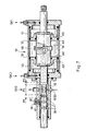
- stage change unit 9 The structure of the stage change unit 9 is clearly visible in FIG. 1.
- stage change member 33 of the change gear 11 is with the piston rod of a pneumatically operated selection cylinder 34 and also a pneuma table actuated switching cylinder 35 connected.
- the selection cylinder 34 has four digits, three of which are brought about by pneumatics, the fourth position, that is to say the basic position by means of a spring. The more detailed announcement of the selection cylinder 34 is not necessary, the four-digit cylinder can even be assembled from several two-digit pneumatic cylinders.
- the shift cylinder 35 - as shown in Fig. 7 - has three digits. Two floating pistons 37 are arranged on the stepped piston rod 36. As a result, the active piston surfaces AK, which are close to the cylinder chamber V0 and which bring about the central position of the piston rod 36, are smaller than the active piston surfaces AS which are close to the cylinder chambers V1 and V2 and which bring about the outer position of the piston rod 36. In this way, the switching cylinder 35 has two pressure force stages in the outer positions of the piston rod 36, depending on whether only the cylinder spaces V1 or V2 which bring about the outer position or also the cylinder space V0 which brings about the middle position are connected to the compressed air source.
- annular grooves 38 are formed at a distance corresponding to the three piston positions, into which the ball 41 of a positioning structure 39 loaded with spring 40 springs.
- this task can also be performed by means of several double-digit pneumatic cylinders.
- Both the selector cylinder 34 and the shift cylinder 35 are connected to the compressed air source (not shown) of the motor vehicle.
- the selector cylinder 34 is controlled by valves SV12, SV56 and SVR
- the shift cylinder 35 is controlled by valves SKO, SK1 and SK2. In terms of their design, these are electromagnetically actuated, two-digit three-way valves.
- the sensors ES12, ES34, ES56 and ESR are used on the piston rod of the selector cylinder 34 to sense the respective position of the stage changing member 33, and the sensor ES0 on the switching cylinder 35. These are inductive sensors.
- a route P0 is drawn on the piston rod 36 as a signal transmitter and routes P1 and P2 on its two sides.
- a constriction 42 is ground in the path P0, so its height deviates from the height measurable in the paths P1, P2.
- Sensor ES0 is located here.
- the width of the constriction 42 is dimensioned such that in the middle position of the piston rod 36 the distance P0, in its outer positions the distance P1 and P2, respectively, reach the sensor ES0. In this way it can be signaled with the single sensor ES0 whether the piston rod 36 or, in another way, the shift cylinder 35 is in the middle position or in the outer position.
- connection between the clutch pedal 8 and the device according to the invention is not necessary. Since we also realized this with the device we implemented Using the connection, our control unit to be described in the following is also structured in this way, we also have to deal with it here.
- a sensor ET that works on an inductive principle. This is arranged such that it generates a signal when the clutch pedal 8 is pressed.
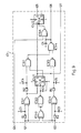
- the control unit 10 serving for the coordinated connection of the remote control unit 7 and the step change unit 9 was designed with the use of electronic elements.
- the task can also be solved with simple relays, but the arrangement of such a control is complicated and takes up an enormous amount of space.
- control unit 10 consists, as shown in FIG. 8, of a subunit 43 which senses the direction, a subunit 44 which counts up and down, a subunit 45 which generates and compares the absolute value, a subunit 46 which controls the movement in the switching direction, and one which Position in the direction of comparison comparing subunit 47, a subunit 48 controlling the movement in the direction of choice and a subunit 49 controlling the electromagnet, further from the adaptation of the signal levels to adaptation stages I and from power amplifiers T for securing the control levels.
- the input 101 through the adaptation stage I At the input 121 of the direction-sensing sub-unit 43 are the input 101 through the adaptation stage I, at the input 122 through the adaptation stage I the input 102, at the input 124 the output 124 of the sub-unit 45 generating and comparing the absolute value, the output 125 at the input 125 of the Absolute value generating and comparing subunit 45, the outputs 126 and 127 connected to the inputs 126 and 127 of the up-down counting subunit 44.
- the forward-backward-counting subunit 44 has, in addition to the inputs 126 and 127 announced above, an input 123 which is connected to the input 103 by an adaptation stage I.
- the outputs 128, 129, 130, 131 and 132 of the up-down counting sub-unit 44 are at the inputs of the same position number of the sub-unit 45 generating and comparing the absolute value, their output 136 is connected to the input 136 of the sub-unit 46 controlling the movement in the switching direction.
- connection of the inputs 128, 129, 130, 131 and 132 of the subunit 45 generating and comparing the absolute value is already known, as is the connection of its output 124.
- the outputs 133 and 135 are at the inputs of the same position number of the control of the movement in the switching direction Subunit 46 connected, whereas its output 134 is connected to the input of the same position number of the subunit 49 controlling the electromagnet.
- connection of the inputs 133, 135 and 136 of the subunit 46 controlling the movement in the switching direction has already been described. From their further inputs, the input 137 and 141 are connected to the outputs of the same position number of the subunit 47 comparing the position in the election direction, and their input 123 is connected to the input 103 by the adaptation stage I already mentioned. From its outputs, output 142 is through a power amplifier T at output 114, and output 138 through one Power amplifier T at output 115, output 139 through a power amplifier T at output 116, and finally output 140 at the input of the same position number of subunit 49 controlling the electromagnet. The power amplifiers T mentioned above are also connected to their input 144 by an adaptation stage I at input 104.
- the inputs 106, 110, 107, 111, 108, 112, 109 and 113 of the subunit 47 comparing the position in the direction of selection are connected to the inputs of the same position number of the control unit 10.
- the connection of the output 137 has already been described, the connection of the output 141 likewise, in addition the output 141 is also connected to the input of the same position number of the subunit 49 controlling the electromagnet.
- the subunit 48 controlling the movement in the direction of selection is connected by its inputs 110, 112 and 113 to the inputs of the same position number of the control unit 10, and the output 146 is connected to the output 117 by a power amplifier T, the output 147 is connected to the output by a power amplifier T 118 and finally the output 148 is connected to the output 119 by a power amplifier T.
- connection of the inputs 134, 140 and 141 is already known from the connection of the inputs of the subunit 49 controlling the electromagnet.
- Input 143 is through an adaptation stage I at input 105
- input 123 is through an adaptation stage I at input 103
- input 144 is through an adaptation stage I at input 104 connected.
- the only output 145 is connected to the output 120 by a power amplifier T.
- control unit 10 The separation of the control unit into subunits is - as can also be seen from its designation - also rational from a functional point of view, and the functioning of the control unit 10 can also be better seen. In reality, however, we have not constructed the control unit 10 from strictly delimitable sub-units. It can be imagined that the subunits can no longer be recognized at all in a control unit constructed from more complicated microelectronic elements and not even the functioning of the control unit can be followed with such an — essentially functional — division.
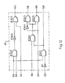
- FIGS. 9 to 15 The circuit diagrams of the above-mentioned subunits are shown in FIGS. 9 to 15.
- the control unit 10 we also used several such electronic elements, which contain several operating units, during the actual development. Since we have not - as already pointed out - the control unit 10 in reality set up for each subunit, some electronic elements can each be found with their one operation unit in one or more subunits, which we have deliberately delimited.
- control unit 10 - with the names of the IC catalog of the technical publisher - from the following elements: a Schmidt trigger IC1 / CD-40106 /, an exclusive one containing four operation units IC2 / 1-IC2 / 4 OR gate IC2 / 4030 /, a NO-AND gate IC3 / 4011 / containing four operating units IC3 / 1-IC3 / 4, a flip-flop of type D IC4 / 4013 / containing the operating units IC4 / 1-IC4 / 2 , a forward and backward counter IC5 and IC6 / 4029 /, a four OR units IC7 / 1-IC7 / 4 including an exclusive OR gate IC7 / 4030 /, a digital comparator with four bits IC8 and IC9 / 74C85 /, a six Operation unit IC10 / 1-IC10 / 6 containing negator IC10 / 4069 /, one each with
- FIGS. 9 to 15 The structure of the individual subunits is based on FIGS. 9 to 15 as follows.
- the input 121 of the direction-sensing sub-unit 43 shown in FIG. 9 is connected directly to one input of the unit IC2 / 1, whereas it is connected to its other input through the resistor R1.
- the common point of the resistor R1 and the unit IC2 / 1 is connected through capacitor C1 to the earth point.
- the input 121 is connected directly to an input of the IC2 / 3 unit.
- the input 122 is directly connected to one input of the unit IC2 / 4, whereas the other input is connected through the resistor R2.
- the common point of the resistor R2 and the unit IC2 / 4 is also connected to the earth point through the capacitor C2.
- the input 122 is connected directly to the other input of the IC2 / 3 unit.
- the output of the IC2 / 1 unit is connected to an input of the IC3 / 1 unit through the resistor R3.
- the common point of the resistor R3 and the unit IC3 / 1 is connected to the earth point through the capacitor C4.
- the output of the IC2 / 1 unit is connected directly to the signal input D of the IC4 / 1 unit.
- the output of the IC2 / 3 unit is connected to both inputs of the IC3 / 2 unit, and the output of the IC3 / 2 unit is directly connected to the clock input CLK of the IC4 / 1 unit and through the capacitor C3 to the reset input R. the unit IC4 / 1 and with the earth point.
- the set input S of the unit IC4 / 1 is at the earth point, its output Q is at the signal input D of the unit IC4 / 2 and at an input of the unit IC3 / 2, whereas its output Q connected to the other input of the IC3 / 1 unit.
- the Q output gives the 127 output.
- the output of the IC2 / 4 unit is connected through resistor R4 to the other input of the IC3 / 2 unit.
- the common point of the resistor R4 and the unit IC3 / 2 is connected to the earth point through capacitor C5.
- the output of the IC3 / 1 unit and the output of the IC3 / 2 unit are each connected to an input of the IC3 / 4 unit.
- the output of the IC3 / 4 unit gives output 126 on the one hand, and on the other hand it is connected to an input of the IC15 / 2 unit.
- the common point of the output of the IC3 / 4 unit and the input of the IC15 / 2 unit is connected to the earth point through the capacitor C6.
- Input 124 is connected to the other input of unit IC15 / 2, whereas its output is connected to clock input CLK of unit IC4 / 2.
- the set input S and the reset input R of the unit IC4 / 2 are connected to the earth point, their output Q gives the output 125.
- the output Q stay free.
- the up-down counter subunit shown in Fig. 10 consists of one up-down counter IC5 and IC6, respectively.
- the inputs A, B, C, D and the admission input CI of the up-down counter IC5 are connected to the earth point. Its clock input CLK is at input 126, its prohibition input PE is at input 123, the binary-decimal counter input B / D is at the supply voltage, the up-under counter input U / D is connected to input 127.
- the outputs QA, QB, QC, QD give the outputs 128, 129, 130, 131, the output C0 signaling the end value is connected to the clock input CLK of the up-down counter IC6.
- the input 125 is at an input of the unit IC2 / 2
- the input 128 is at an input of the unit IC7 / 4
- the input 129 is at an input the unit IC7 / 1, the input 130 connected to an input of the unit IC7 / 2, the input 131 to an input of the unit IC7 / 3.
- the other input of the units IC2 / 2, IC7 / 4, IC7 / 1, IC7 / 2 and IC7 / 3 are connected to one another and to the input 132.
- the unit IC2 / 2 gives the output 133.
- the output of unit IC7 / 4 is at input A0, whereas the output of unit IC7 / 1 is at input A1, the output of unit IC7 / 2 at input A2 and the output of unit IC7 / 3 at input A3 of digital comparator IC8 and of the digital comparator IC9 connected.
- the output A> B of the digital comparator IC8 gives the Outputs 124 and 134
- output A> B of the digital comparator IC9 gives the output 135.
- the input 133 is connected to an input of the unit IC11 / 2 and the unit IC11 / 1, as shown in FIG. 12.
- Input 135 is connected to the other input of unit IC11 / 2, whereas its output is connected by unit IC10 / 2 to an input of unit IC15 / 2.
- the other input of the IC15 / 2 unit is connected to the input 141, its output gives the output 142.
- the Schmidt trigger IC1 connects input 123.
- the output of the IC11 / 1 unit is connected on the one hand to an input of the IC12 / 1 unit, on the other hand it gives the output 140.
- the other input of the IC12 / 1 unit is connected to the input 136, whereas its output has an input of the IC12 unit / 2 and the unit IC12 / 3 connected.
- the other input of the IC12 / 3 unit is direct, whereas the other input of the IC12 / 2 unit is connected to the input 137 by the IC10 / 1 unit.
- the output of the IC12 / 2 unit gives the output 138 and the output of the IC12 / 3 unit gives the output 139.
- the inputs 106 and 110 of the subunit 47 comparing the position in the election direction are at the inputs of the unit IC13 / 4, the inputs 107 and 111 at the inputs of the unit IC13 / 1, the inputs 108 and 112 at the inputs of the Unit IC13 / 3, and the one gears 109 and 113 connected to the inputs of the IC13 / 2 unit.
- the output of the unit IC13 / 4 is through the diode D5, the output of the unit IC13 / 1 through the diode D6, the output of the unit IC13 / 3 through the diode D7, finally the unit IC13 / 2 through the diode D8 with each other and directly connected to the output 137, through the unit IC10 / 5 to the output 141 and through the resistor R6 to the earth point.
- the input of the subunit 48 controlling the movement in the direction of selection is at one input of the unit IC11 / 3, its input 112 on the one hand through the unit IC10 / 3 at the other input of the unit IC11 / 3 and on the other hand through the unit IC14 / 3 connected to the output 147, and finally its input 113 through the unit IC14 / 4 to the output 148.
- the output of the IC11 / 3 unit gives the output 146 through the IC14 / 1 unit.
- the subunit 49 controlling the electromagnet - as can be seen in FIG. 15 - also contains the block 50 which delays the switching on of the electromagnet and the block 51 which tempers the dissolution of the electromagnet.
- the input 134 is connected through the resistor R9 on the one hand to an input of the unit IC15 / 1, and on the other hand through the capacitor C7 at the earth point.
- the resistor R9 and the capacitor C7 form the block 50 which delays the switching on of the electromagnet.
- the input 143 is on the one hand at an input of the unit IC15 / 3, on the other hand through the unit IC14 / 5, the capacitor C8 and the unit IC10 / 1 connected to the other input of the unit IC15 / 1.
- the block 51 which tempers the dissolution of the electromagnet consists of the unit IC14 / 5, the capacitor C8, the unit IC10 / 1, and furthermore the resistor R5 connecting the common point of the two last-mentioned components to the earth point.
- Input 140 is connected to the other input of the IC15 / 3 unit.
- the output of the IC15 / 3 unit and the output of the IC15 / 1 unit are each connected to an input of the IC11 / 1 unit.
- the output of the IC11 / 1 unit is connected to the output 145 through the diode D1.
- the input 141 is also connected to the output 145 through the diode D2.
- the input 123 is through the diode D4, the input 144 is directly at the input of the unit IC10 / 4, whereas the output of the unit IC10 / 4 is also connected at the output 145 through the diode D3.
- the adaptation stages I and power amplifier T have no control task, they are not part of the invention. It is therefore unnecessary to publish them in detail because their assembly is a routine task for a person skilled in the art.
- the remote switching device described above works as follows.
- the remote switching device is integrated in the electrical network of the motor vehicle in such a way that it is energized earlier than the engine can be started.
- the power amplifiers T switch voltage to the solenoid of the valves through the outputs 114, 115, 116 SK0, SK1, SK2.
- the valves SK0, SK1, SK2 open and let compressed air from the compressed air source into the cylinder spaces V0, V1 and V2 of the shift cylinder 35. Since each cylinder space of the shift cylinder 35 is filled in this way, the forces acting on the pistons 37 are in equilibrium Piston rod 36 does not move.
- the subunit 49 controlling the electromagnet does not yet generate a signal on the effect of the signal arriving at its input 144, this signal is only an approval signal for this subunit.
- the vehicle driver To move the motor vehicle, the vehicle driver must switch to gear stage 1. To do this, he moves the remote control lever 12 in the direction of selection v to the switching route 1-2 times .
- the plate 15 arranged at the end of the remote control lever 12 passes through the sensor EV12, which gives a signal to the input 110 of the control unit 10. From here, the signal arrives at the input of the subunit 48 controlling the movement in the election direction and at the input of the subunit 47 comparing the position in the election direction.
- the subunit 48 controlling the movement in the direction of selection generates at its output 146 a signal for the power amplifier T which, via its output 117, switches voltage to the electromagnet of the valve SV12.
- the valve SV12 lets compressed air into the corresponding space of the selector cylinder 34, whereby the latter moves the stage change member 33 in the direction of selection v to the switching line 1-2 times .
- the success of the selection is perceived by the sensor ES12, which gives a signal to the input 106 of the control unit 10.
- the signal arriving at input 106 is compared by the subunit 47 comparing the position in the direction of selection with the signal arriving at input 110.
- the switching Strasse 1-2 x - are 47 generates the position comparative in choosing the direction of sub-unit a signal on their outputs 137 and 141 for the subunit 46 controlling the movement in the switching direction, or at its output 141 for the subunit 49 controlling the electromagnet.
- the subunit 49 controlling the electromagnet will generate a signal for the power amplifier T, which relaxes the electromagnet M, on the effect of the signal arriving at its input 144 and on the effect of the signal arriving at its input 141 - which are also approval signals for it.
- the electromagnet M which previously held the loop 21, now lets go of it. In this way, the remote control lever 12 can now also be moved in the switching direction k .
- the vehicle driver now guides the remote control lever 12 1-2 times in the switching direction in the switching direction k against the position corresponding to gear stage 1.
- the signal transmitter unit 18 With the movement of the remote control lever 12, the signal transmitter unit 18 also moves. During the movement, the column 19 moves away from the sensor EK0, which gives a signal for the input 103 of the control unit 10. The feeler EK0 therefore feels that the signal transmitter unit 18 has moved out of the central position.
- the columns 20 When the signal transmitter unit 18 moves, the columns 20 also move. In this case, the movement is such that the column 20 with the row number 0 first completely leaves the sensor EK2 and then the sensor EK1.
- the sensor EK2 generates a signal at the input 102 of the control unit, and the sensor EK1 a signal at the input 101.
- the signal of the sensor EK2 and the signal of the sensor EK1 pass through the corresponding adaptation stage I into the direction-sensing sub-unit 43.
- the direction-sensing sub-unit 43 determines the direction of movement of the remote control lever 12 in the switching direction k from the fact that the signal from the sensor EK2 arrived earlier than the signal from the sensor EK1.
- the signal of sensor EK0 arriving at input 103 also passes through the adaptation stage into the up-down counting sub-unit 44.
- This signal is a command that the up-down-counting sub-unit 44 should start counting the pulses.
- the pulses to be counted pass from the signal of the sensors EK2, EK1 through the direction-sensing sub-unit 43 into the up-down counting sub-unit 44.
- the forward-backward counting subunit 44 leads the current result of the counting into the subunit 45 generating and comparing the absolute value.
- the subunit 45 which generates and compares the absolute value, compares the current result of the counting with the values which have been predetermined and fed in by us.
- the direction-sensing sub-unit 43 determines the direction of movement of the signaling unit 18.
- the direction-sensing sub-unit 43 also feeds this information in the form of a signal directly into the sub-unit 45 generating and comparing the absolute value.
- the sub-unit 45 generating and comparing the absolute value forwards the signal into the sub-unit 46 controlling the movement in the switching direction, which by means of the for the power amplifier T signal relaxes the solenoid of the valve SK2.
- the valve SK2 empties the cylinder space V2 of the shift cylinder 35.
- the unit 45 also sends a signal into the subunit 49 controlling the electromagnet.
- the subunit 49 controlling the electromagnet sets the electromagnet M - by means of the delay set with the block 50 which delays the activation of the electromagnet - with that of the power amplifier T. supplied signal under voltage, whereby the electromagnet M fastens the loop 21.
- the remote control lever 12 stops, in such a way that the column 20 with the row number -2 of the signal transmitter unit 18 is in front of the sensors EK2, EK1.
- the blocking of the remote control lever 12 signals to the vehicle driver that the synchronization of gear stage 1 is in progress.
- the remote control lever 12 can be pushed a little further compared to the attached loop 21 against the spring 24. If the vehicle driver has the remote control lever 12 abutted on the abutment surface 25 of the loop 21, the column 20 with the row number -4 of the signaling unit 18 arrives in front of the sensors EK2, EK1. Now the subunit 45 generating and comparing the absolute value generates a newer signal for the subunit 46 controlling the movement in the switching direction, which now also relaxes the electromagnet of the valve SK0 by the signal supplied to the power amplifier T. The valve SK0 also empties the cylinder space V0 of the shift cylinder 35. As a result, the piston rod 36 will continue to work with a larger pressure force level.
- the piston rod 36 will complete the engagement of gear stage 1 with the aid of the stage changing member 33.
- the piston rod 36 reaches its outer position, the ball 41 of the positioning structure 39 jumps into the groove 38 formed in the piston rod 36.
- the remote control lever 12 strikes the line 32.
- the column 20 with the row number -10 of the signal transmitter unit 18 arrives in front of the sensors EK2, EK1.
- the absolute value generating and comparing subunit 45 again generates a signal for the electromagnet controlling subunit 49 which, after delaying the block 50 which delays the switching on of the electromagnet, by means of a signal supplied to the power amplifier T, again energizes the electromagnet M, which activates the Loop 21 reattached. The delay is necessary so that the spring 24 can return to its normal position.
- the vehicle driver evaluates the above-mentioned impact of the remote control lever 12 in such a way that the gear shift of gear stage 1 has been completed, so he closes the clutch.
- the release of the clutch pedal 8 is perceived by the sensor ET, the corresponding power amplifier T also relaxes the electromagnet of the valve SK upon the effect of its signal.
- the valve SK1 will also empty the cylinder space V1 of the shift cylinder 35.
- the piston rod 36 is held in this position by the positioning structure 39.
- the movement of the remote control lever 12 remains one step behind the gear stage shift actually implemented by the shift cylinder 35.
- This "swindling" of the vehicle driver does not cause any disadvantage, but the remote control lever 12 fully simulates the movement of the traditional shift lever.
- the control unit energizes the electromagnet of the valve SK1.
- the cylinder space V1 of the shift cylinder 35 is filled.
- the signal generated by the sensor ET is at the same time the one admission signal for switching on the voltage of the electromagnet M.
- the control unit will accordingly not yet relax the electromagnet M.
- the vehicle driver then pulls the remote control lever 12 against its central position. Since the electromagnet M still holds the loop 21 firmly, the remote control lever 12 can only be moved to a small extent against the spring. This is sufficient for the signal transmitter unit 18 to move and the column 20 with the row number -8 to reach the sensors EK1, EK2.
- the signal generator unit 18 is start covering these sensors in reverse order from those previously described.
- the control unit 10 will determine from the signal of the sensors EK1, EK2 already when starting the signal generator unit 18 that the movement of the signal generator unit 18 is in the opposite direction, therefore it will relax the electromagnet of the valve SK1 and energize the electromagnet of the valve SK0.
- control unit 10 again energizes the electromagnets of the valves SK1 and SK2, which also fill the cylinder spaces V1 and V2 of the shift cylinder 35. In this way, all three cylinder spaces are filled up again, of course there is also a balance of forces.
- the vehicle driver again moves the remote control lever 12 against its central position.
- the columns 20 of the signal generator unit 18 will now run in front of the sensors EK1, EK2 in the opposite direction.
- the control unit 10 determines that the direction of movement of the Sig Sensor unit 18 has changed, but that column 20 of signaling unit 18 has not yet reached sensor EK0. Therefore, it will immediately relax the solenoid of the valves SK1 or SK2 which brings about the shifting of the planned gear stage and is therefore energized. Compressed air remains only in the cylinder space V0 of the shift cylinder 35, so the piston rod 36 returns to the central position.
- the remote control lever 12 and the step change element 33 were in neutral position N when the motor vehicle was started.
- the motor vehicle can also be parked in such a way that any gear remains engaged. In this case, the vehicle driver starts cranking as we have described the gear stage deactivation above. It can also happen that when the motor vehicle is parked, the remote control lever 12 is in the middle position, but not in the switching route 3-4 times . It is very important here that if there is no compressed air in any of the cylinder spaces of the selection cylinder 34, the built-in spring places its piston rod 3-4 times to the switching route, or in the same way the springs 27 and 29 also the remote control lever 12 to switching route 3- 4 times .
- the selector cylinder 34 should first take up the position that is the same as the position of the remote control lever 12 when the remote switching device is set under voltage.
- the configuration of the signal generator unit 18 can not only be comb-like - as described here. Another variant is shown in FIG.
- the signaling unit 53 can - with regard to their type order and shape - be the same with the signaling unit 18. The difference is that it does not have gaps, but circular openings.
- p 1 are seven holes 54, p in the path 2, an opening 55 is formed.
- the function of the opening 54 is the same as that of the columns 20, which is why they are drawn with the row number which corresponds to the positions of the columns 20.
- the opening 55 is also arranged in the same way as the column 19.
- the sensors EK1, EK2 are arranged in the movement path p 1 of the openings 54, the sensor EK0 in the movement path p 2 of the opening 55.
- the distance s / 2 of the displacement of the sensors EK1 and EK2 is also equal to half the field of view f .
- This value s / 2 could also be larger, but it is not expedient to choose larger from the value of the visual range f , since openings 54 which are too large would have to be made, as a result of which the functioning of the remote switching device would be imprecise.
- the signal transmitter unit 53 essentially fulfills its task in the same way as the signal transmitter unit 18. Only the structure of the control unit 10 and within which the basic data introduced into the subunit 45 generating and comparing the absolute value are to be modified .
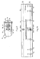
- the remote control unit can also be constructed in other ways.
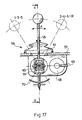
- An example of this is that in FIGS. 17 and 19 Remote control unit 56 shown, which is shown for simplicity with a structure corresponding to the actuation of the previously described change gear 11.
- the circuit diagram 52 is also characteristic of the remote switching unit 56, and the step change unit 9 of the change gear 11 is also of identical construction.
- the remote control lever 58 is installed so as to be rotatable about the axis 59 in the switching direction k and about a bolt 60 perpendicular thereto in the direction of selection v .
- a line 61 is formed in the upper plate of the housing 57 for guiding the switching lever 58, which line is essentially the carrier of the circuit diagram 52 in the known manner.
- the spring 62 arranged about the axis 59 serves to hold the remote control lever 58 in a neutral position N, the spring 62 being supported at one end on the remote control lever 58 and at the other end on the housing 57.
- a shorter spring 63 is arranged in the spring 62 to secure against the involuntary switching of the reduction stage R.
- a plate 70 is provided which actuates the sensors EV12, EV34, EV56, EVR arranged in the direction of selection v , which are inductive sensors.
- a signal transmitter unit 64 is attached to one end of the axis 59.
- the signal transmitter unit 64 has, in a manner visible in FIG. 20, a wider arcuate outer surface, in front of which for the purpose of perceiving the movement sensors EKK1, EKS1, EKS2, EKK2 are arranged in switching direction k , which are also inductive sensors.
- the arc length i of the jacket of the signal transmitter unit 64 is selected such that the sensors EKK1, EKS1, EKS2, EKK2 are arranged in comparison to one another in such a way that the signal transmitter unit 64 can cover each sensor separately as well as the neighboring ones.
- a loop 65 is attached to the other end of the axis 59.
- a pneumatic working cylinder 68 is arranged perpendicular to the friction surface 66 of the loop 65.
- the pneumatic working cylinder 68 is dimensioned such that when it is pressurized, its piston rod 67 on the friction surface 66 awakens such a large friction force that can be overcome by means of medium-sized hand force exerted on the remote control lever 58.
- the loop 65 and the pneumatic cylinder 68 together form the brake mounting structure F.
- the pneumatic working cylinder 68 is connected to the compressed air source through the line 69 and through the electromagnetically actuated valve SF.
- the connection between the remote control unit 56 and the stage change unit 9 is also established here by a control unit.
- the signal transmitter unit 64 of the remote control unit 56 and the sensors EKK1, EKS1, EKS2, EKK2 actuated by the signal transmitter unit differ in terms of their arrangement and number from the exemplary embodiment described above, the configuration of the control unit, knowing the functioning, can pose no problem for a person skilled in the art, so we will do not advertise this here.
- the signal generation in the direction of choice v and the response of the level change unit 9 are identical to the previous one.
- the control unit 9 If the step change unit 9 has not selected the switching route corresponding to the position of the remote control lever 58, the control unit energizes the solenoid of the valve SF.
- the valve SF fills the pneumatic working cylinder 68, the piston rod 67 of which clamps against the friction surfaces 66. As a result, the loop 65 is braked, a greater hand force is required to move it. The vehicle driver learns from this that any irregularity has occurred.
- the remote control lever 58 can be moved easily in the selected shift route.
- the sensors EKS1 and EKS2 are covered by the signal transmitter unit 64.
- the control unit will also keep the cylinder spaces V0, V1 and V2 of the shift cylinder 35 in a filled state on the basis of the common signal from the sensors EKS1 and EKS2.
- the remote control lever 58 is more difficult to move with the brake 65 braked. If the vehicle driver overcomes this braking effect by pushing the remote control lever 58 further, the signaling unit 64 continues to rotate and will cover the sensors EKS1 and EKK1 at the same time, and on the action of the common signal of these sensors the control unit will also give a command to empty the cylinder space V0 of the switching cylinder 35 . Now the gear stage 1 is switched with the larger pressure force stage.
- the control unit releases the brake mounting structure F by switching off the solenoid of the valve SF.
- the vehicle driver pushes the remote control lever 58 in the switching route 1-2 times all the way to the outer position, now the signaling unit 64 rotates away from the sensor EKS1 and only covers the sensor EKK1.
- the control unit issues a command based on the independent signal of the EKK1 sensor Emptying the cylinder space V1 of the shift cylinder 35 and closing the brake mounting structure F.
- the engagement of gear stage 1 is complete, all three cylinder spaces of the shift cylinder 35 are empty, the remote control lever 58 is attached.
- the signal generator unit 64 now also covers the sensor EKS1.
- the signals of the sensors EKK1 and EKS1 now appear in the control unit in reverse order, and this is evaluated by the control unit in such a way that it only issues a command to fill up the cylinder space V0 of the shift cylinder 35. In this way, gear stage 1 is deactivated.
- the control unit 64 If the signal transmitter unit 64 leaves the sensor EKK1 by withdrawing the remote control lever 58, the control unit issues a command to release the brake mounting structure F.
- the remote control lever 58 can return to its central position.
- the loop 65 can twist in relation to the axis 59.
- One arm of the rocker 71 is designed as a stop 72, which can move between the abutment surfaces 73 formed on the loop 65.
- the other arm 74 of the rocker 71 is supported against the loop 65 with a spring 75 each.
- the piston rod 67 of the pneumatic working cylinder 68 can grip the loop immovably.
- the abutment surfaces allow the stop 72 to move to such an extent that when the sensors EKK1, EKS1, EKS2, EKK2 are actuated by the remote control lever 58, the two adjacent positions can still be achieved compared to the fixed position.
- the springs 75 have the same function as the springs 23 and 24 in the remote control unit 7 described earlier.
- the signal transmitters of the remote control unit 56 described above in the switching direction k can also be designed in the manner described for the remote control unit 7. The only difference is that the signal transmitter unit 18 is to be manufactured in an arc shape. It is also evident that the remote switching unit 56 described above can also be constructed with optotors instead of inductive sensors.
- the pneumatic working cylinder moving the step changing element of the change gear in the switching direction is also constructed in this way the same pressure in all three positions gives the same pressure.
- a pressure reducer is to be interposed between the valve bringing the middle position and the compressed air source.
- a hydraulic working cylinder can also be used in the brake fastening construction F, in particular in the embodiment variant which was announced last.
Abstract
Description
Die Erfindung bezieht sich auf eine Fernschaltvorrichtung, mit deren Hilfe der Fahrzeugfahrer - mit der Illusion der Handbetätigung des traditionellen Schalthebels - fehlerfrei fähig ist, die Schaltung der Gangstufen bei dem von ihm entfernt angeordneten synchronisierten mechanischen Wechselgetriebe durchzuführen.The invention relates to a remote switching device, by means of which the vehicle driver - with the illusion of manual operation of the traditional shift lever - is able to carry out the shifting of the gear stages with the synchronized mechanical change gear arranged remotely.
Es ist bekannt, dass bei einem Teil der Kraftfahrzeuge, in erster Reihe bei den Kraftfahrzeugen mit Heckmotor, oder bei verschiedenen Arbeitsmaschinen das Wechselgetriebe vom Fahrzeugfahrer entfernt angeordnet ist, so dass das Stufenwechselorgan des Wechselgetriebes mittels unmittelbarer Handbetätigung nicht betätigt werden kann. Geringere Entferungen können mit einem Gestängemechanismus oder Bowdenkabel überbrückt werden, aber bei derartigen, mit Gelenk aufgebauten Kraftfahrzeugen oder Arbeitsmaschinen, wo der Fahrzeugfahrer auf dem einen Gelenkglied sitzt und das Wechselgetriebe am anderen Gelenk angeordnet ist, können diese Lösungen nicht mehr verwendet werden.It is known that in some of the motor vehicles, primarily in the case of motor vehicles with a rear engine, or in the case of various working machines, the change gearbox is arranged away from the vehicle driver, so that the step change element of the change gearbox cannot be actuated by direct manual actuation. Shorter distances can be achieved with a rod mechanism or Bowden cables are bridged, but these solutions can no longer be used in such articulated motor vehicles or work machines, where the vehicle driver sits on one articulated link and the change gear is arranged on the other articulated joint.
Zur Lösung des Problems sind hydraulische und pneumatische Systeme ausgearbeitet worden. Das Wesen der hydraulischen Systeme besteht darin, dass der Fahrzeugfahrer mit Hilfe des Schalthebels in zueinander senkrechten Zylindern Kolben bewegt und durch die aus den Zylindern auf diese Weise ausgedrückte Hydraulikflüssigkeit sind die Kolben der mit dem Stufenwechselorgan des Wechselgetriebes verbundenen Arbeitszylinder betätigt. Derartige Lösungen sind aus den DE-OS 25 10 392, DE-OS 27 00 837, DE-OS 29 35 377 und HU-PS 192.487 kennenzulernen. Die hydraulischen Systeme basieren also auf dem Prinzip der unmittelbaren Kräfteübertragung, und so muss der Fahrzeugfahrer infolge der Flüssigkeitsreibung bei grösseren Entfernungen eine verhältnismässig grosse Kraft ausüben.Hydraulic and pneumatic systems have been developed to solve the problem. The essence of the hydraulic systems is that the vehicle driver moves pistons in mutually perpendicular cylinders with the aid of the shift lever, and the pistons of the working cylinders connected to the step change element of the change gear are actuated by the hydraulic fluid expressed in this way from the cylinders. Such solutions are known from DE-OS 25 10 392, DE-OS 27 00 837, DE-OS 29 35 377 and HU-PS 192.487. The hydraulic systems are therefore based on the principle of direct power transmission, and so the vehicle driver has to exert a relatively large force due to the fluid friction over longer distances.
Bei den oben erwähnten Lösungen erfolgte eine einfache Kräfte- und Bewegungsübertragung, so konnte der Fahrzeugfahrer den Schalthebel auf dieselbe Weise bewegen, als müsste er einen traditionellen Schalthebel behandeln.With the above-mentioned solutions, a simple transfer of power and movement took place, so that the vehicle driver could move the shift lever in the same way as if he had to treat a traditional shift lever.
Bei den pneumatischen Systemen ist das Stufenwechselorgan des Wechselgetriebes mit der Kolbenstange des in Schaltrichtung und Wahlrichtung angeordneten Schaltzylinders bzw. Wahlzylinders verbunden. Der Schaltzylinder und der Wahlzylinder sind durch Ventile am Pressluftsystem des Kraftfahrzeuges angeschlossen. Der Fahrzeug fahrer behandelt diese Ventile auf mechanischem Wege oder durch elektrische Steuerung.In the pneumatic systems, the step changer of the change gearbox is connected to the piston rod of the shift cylinder or selector cylinder arranged in the switching direction and selection direction. The shift cylinder and the selection cylinder are connected to the compressed air system of the motor vehicle by valves. The vehicle The driver treats these valves mechanically or through electrical control.
Bei einem Teil der pneumatischen Systeme soll der Fahrzeugfahrer zur elektrischen Steuerung nur Schaltknöpfe drücken oder einen, bei automatischen Wechselgetrieben üblichen Kontrollerarm ziehen. Wenn derartige Systeme einfach sind, sind sie ungenau, es bestehen zahlreiche Fehlermöglichkeiten des Fahrzeugfahrers, weiterhin geht das Wechselgetriebe sehr vorzeitig zugrunde. Die besseren, zuverlässigeren, schonender funktionierenden Systeme sind hingegen sehr kompliziert. Aus diesem Grund hat sich die Entwicklung gegen derartige Systeme verschoben, die in jedwelchem Mass die Bedienung des traditionellen Schalthebels simulieren.In some of the pneumatic systems, the vehicle driver is only supposed to press the switch buttons for electrical control or pull a control arm, which is common in automatic change gearboxes. If such systems are simple, they are inaccurate, there are numerous possible errors for the vehicle driver, and the change gearbox also dies prematurely. The better, more reliable, gentler systems, on the other hand, are very complicated. For this reason, the development has shifted against systems of this type, which simulate the operation of the traditional shift lever to any extent.
Ein derartiges elektropneumatisches System ist in der HU-PS 187.345 beschrieben. Bei dieser Lösung ist neben dem Fahrzeugfahrer eine derartige Fernschalteinheit eingebaut, deren Fernschalthebel durch den Fahrzeugfahrer dem traditionellen Schaltbild entsprechend bewegt ist. Der Fernschalthebel betätigt in seiner, jeder Gangstufe entsprechenden Stellung je einen elektrischen Schalter, und diese Schalter schalten den Elektromagnet derjenigen Ventile ein, die den das Stufenwechselorgan bewegenden pneumatischen Schaltzylinder und Wahlzylinder steuern. Dieses System informiert den Fahrzeugfahrer über den Verlauf der Schaltung der Gangstufe nicht, höchsten ist das Ende dieses Verlaufes durch eine Signallampe signalisiert. Da die pneumatischen Arbeitszylinder zu hart funktionieren, sind vor ihnen Drosselventile zwischengebaut, aber auch so sind sie nur zu derartigen Wechselgetrieben empfohlen, die durch einen hydrodynamischen Momentwandler mit dem Motor verbunden sind.Such an electropneumatic system is described in HU-PS 187.345. In this solution, a remote control unit of this type is installed in addition to the vehicle driver, the remote control lever of which is moved by the vehicle driver in accordance with the traditional circuit diagram. The remote control lever actuates an electrical switch in its position corresponding to each gear stage, and these switches switch on the electromagnet of those valves which control the pneumatic switching cylinder and selector cylinder which moves the stage changing element. This system does not inform the vehicle driver of the course of the gear shift, the end of this course is signaled by a signal lamp. Since the pneumatic working cylinders work too hard, throttle valves are installed in front of them, but also they are only recommended for change gearboxes that are connected to the engine by a hydrodynamic torque converter.
Die aus der DE-OS 31 38 827 erkennbare Fernschalteinheit ist bei im wesentlichen derartigen Systemen verwendbar. Hier sind anstatt elektrische Schalter Magnete und Sensoren entsprechender Anzahl angeordnet, und zwar derart, dass den einzelnen Stellungen des Fernschalthebels eine gegebene Signalkombination entspricht.The remote control unit recognizable from DE-OS 31 38 827 can be used in essentially such systems. Instead of electrical switches, magnets and sensors of an appropriate number are arranged here, in such a way that the individual positions of the remote control lever correspond to a given signal combination.
Ähnliche Zielsetzung hat die in der US-PS 4.646.582 beschriebene Fernschalteinheit. Diese ist sicherheitsvoller als die vorangehende Lösung, weil sie mittels eines durch Feder belasteten Kugelorientierer in ihrer jeweiligen eingestellten Stellung befestigt ist, weiterhin eine pneumatisch betätigte Konstruktion hat, die den Fernschalthebel solange in Mittelstellung hält, bis die Bedingungen zur Stufenschaltung des Wechselgetriebes bei dem Stufenwechselorgan nicht erfüllt sind.The remote control unit described in US Pat. No. 4,646,582 has a similar objective. This is safer than the previous solution because it is fixed in its respective set position by means of a spring-loaded ball orienter, and has a pneumatically actuated construction that keeps the remote control lever in the middle position until the conditions for the step change of the gearbox are not in the step change element are fulfilled.
Die Fehlermöglichkeit des Fahrzeugfahrers ist gut ausgeschlossen und auch die Betätigung des Stufenwechselorgans ist schonender durchgeführt durch die Fernschaltvorrichtung laut der US-PS 4.516.669. Die Einschaltung der Gangstufe kann nur im aufgelösten Zustand des Wechselgetriebes durchgeführt werden und das Wechselgetriebe kann nur geschlossen werden, wenn die Schaltung regelmässig beendet worden ist.The possibility of error for the vehicle driver is well excluded and the actuation of the stage change element is carried out more gently by the remote switching device according to US Pat. No. 4,516,669. The gear stage can only be engaged when the gearbox is in the disengaged state and the gearbox can only be closed if the gearbox has been terminated regularly.
Aus der US-PS 4.633.987 ist eine rein pneumatisch gesteuerte Fernschaltvorrichtung kennenzulernen. Auch diese kann nur im aufgelösten Zustand des Wechselgetriebes be tätigt werden, und der Fernschalthebel kann nur dann in der Schaltstrasse in seine äussere Stellung geschoben werden, wenn die Schaltung beendet worden ist. Dafür sorgen pneumatische Zylinder.From US-PS 4,633,987 a purely pneumatically controlled remote switching device can be learned. This too can only be in the dissolved state of the change gear can be made, and the remote control lever can only be pushed into its outer position in the switchgear when the shift has been completed. Pneumatic cylinders take care of that.
Eine den Anforderungen am meisten entsprechende Lösung ist in der US-PS 4.646.870 beschrieben. Diese ist eine elektropneumatische Fernschaltvorrichtung, bei der sowohl die Bewegungen des Fernschalthebels als auch die Bewegungen des Stufenwechselorgans des Wechselgetriebes durch analoge Signalgeber, und zwar Potentiometer signalisiert sind. Auch bei dieser Vorrichtung ist durch einen pneumatischen Arbeitszylinder die Schiebung des Fernschalthebels in äussere Stellung vor Beendigung der Stufenschaltung verhindert.One solution that best meets the requirements is described in US Pat. No. 4,646,870. This is an electropneumatic remote control device in which both the movements of the remote control lever and the movements of the step change member of the change gear are signaled by analog signal generators, namely potentiometers. In this device too, the pneumatic control cylinder prevents the remote control lever from being pushed into the outer position before the tap changer has ended.
Wie es ersichtlich ist, erfüllen die Fernschaltvorrichtungen auch heute mehrere Bedingungen, doch können sie nicht als vollkommen betrachtet werden. Es ist bekannt, dass die Einschaltung der Gangstufe bei synchronisierten Wechselgetrieben in zwei Schritten erfolgt. Erst tritt die Synchronkonstruktion ein, und erst nach dem Synchronisieren erfolgt die tatsächliche Schaltung. Die Synchronisierung erfordert weniger, die Schaltung mehr Kraft. Der Fahrzeugfahrer fühlt diese zwei Schritte am traditionellen Schalthebel. Das ist die wichtigste Bedingung der schonenden Stufenschaltung, und eben das fehlt bei den bisherigen Lösungen.As can be seen, the remote switching devices still meet several conditions today, but they cannot be considered complete. It is known that the gear stage is engaged in two steps in synchronized change gearboxes. The synchronous construction only occurs and the actual switching takes place only after the synchronization. The synchronization requires less, the shift more power. The vehicle driver feels these two steps on the traditional gear lever. This is the most important condition for gentle step switching, and that is exactly what is lacking in previous solutions.
Zielsetzung unserer Erfindung ist also eine elektropneumatische Fernschaltvorrichtung zu schaffen, die für das Wechselgetriebe die Schalthebelbehandlung des sorg fältigen Fahrzeugfahrers vollständig simuliert, und für den Fahrzeugfahrer den Verlauf der Stufenschaltung vollständig simuliert.The aim of our invention is therefore to provide an electropneumatic remote switching device which ensures the shift lever treatment of the change gear complex vehicle driver fully simulated, and for the vehicle driver the course of the tap change fully simulated.
Unsere Erfindung basiert auf der Erkenntnis, dass mit Hilfe von entsprechendem pneumatischem Arbeitszylinder oder entsprechenden pneumatischen Armaturen die während der Stufenschaltung erforderliche Kraft zweier Grössen zustandegebracht werden kann. Zugleich kann die Bewegung des Fernschalthebels mit Hilfe von Signalgebern entsprechender Anzahl und einer Brems-Befestigungskonstruktion hinsichtlich Mass der Bewegung und der zur Bewegung erforderlichen Kraft derart geregelt werden, wie sich der traditionelle Schalthebel bewegt.Our invention is based on the knowledge that with the aid of a corresponding pneumatic working cylinder or corresponding pneumatic fittings, the force of two sizes required during the stepping can be achieved. At the same time, the movement of the remote control lever can be regulated with the help of signal transmitters of the appropriate number and a brake mounting structure with regard to the amount of movement and the force required for movement, in the same way as the traditional shift lever moves.
Die Erfindung bezieht sich also auf eine elektropneumatische Fernschaltvorrichtung, insbesondere zur Schaltung der Gangstufen des synchronisierten mechanischen Wechselgetriebes von Kraftfahrzeugen, wobei mit dem Stufenwechselorgan des Wechselgetriebes ein in Wahlrichtung angeordneter pneumatischer Wahlzylinder mit,der Anzahl der Schaltstrassen entsprechender Stellunganzahl und ein in Schaltrichtung angeordneter, über drei Stellungen verfügender Schaltzylinder in Betätigungsverbindung stehen, und der Wahlzylinder und der Schaltzylinder mittels durch Elektromagnet betätigten Ventilen an der Pressluftquelle angeschlossen sind, weiterhin verfügt die elektropneumatische Fernschaltvorrichtung über eine durch den Fahrzeugfahrer bediente Fernschalteinheit mit einem Fernschalthebel mit, dem Schaltbild des Wechselgetriebes entsprechenden Stellungen, welcher mit in Wahlrichtung und Schaltrichtung angeordneten Signalgebern in Betätigungsverbindung steht, und diese durch eine Steuereinheit mit den durch Elektromagnet betätigten Ventilen verbunden sind. Die Vorrichtung kann dadurch gekennzeichnet werden, dass der Schaltzylinder in seinen äusseren Stellungen über eine geringere und eine grössere Druckkraftstufe verfügt; dass in der Fernschalteinheit in Wahlrichtung so viele Signalgeber angeordnet sind, wie viel die Anzahl der Schaltstrassen ist; dass in Schaltrichtung mindestens im Vergleich zur Mittelstellung symmetrisch je zwei Signalgeber angeordnet sind, von denen die der Mittelstellung näher liegenden Signalgeber mit in den äusseren Stellungen des Schaltzylinders geringere Druckkraftstufe zustandebringenden Ventilen in Steuerungsverbindung stehen, und die von der Mittelstellung ferner liegenden Signalgeber mit in den äusseren Stellung des Schaltzylinders grössere Druckkraftstufe zustandebringenden Ventilen in Steuerungsverbindung stehen; dass der Schaltzylinder über mindestens je einem die Endstellung signalisierenden Signalgeber verfügt; dass in der Fernschalteinheit der Fernschalthebel mit einer mittels Hilfsenergie betätigten Brems-Befestigungskonstruktion in Zwangsverbindung steht, und mit der Brems-Befestigungskonstruktion die in der Fernschalteinheit in Schaltrichtung angeordneten Signalgeber und die die Endstellung des Schaltzylinders signalisierenden Signalgeber in Steuerungsverbindung stehen.The invention therefore relates to an electropneumatic remote switching device, in particular for switching the gear stages of the synchronized mechanical change gear of motor vehicles, with the step change organ of the change gear a pneumatic selection cylinder arranged in the direction of selection with a number of positions corresponding to the number of switch routes and one arranged in the direction of switching, over three Positions of the shift cylinder in operation are connected, and the selection cylinder and the shift cylinder are connected to the compressed air source by means of valves actuated by electromagnets. Furthermore, the electro-pneumatic remote control device has a remote control unit operated by the vehicle driver with a remote control lever with positions corresponding to the circuit diagram of the change gearbox, which with in election direction and Switching direction arranged signal transmitters is in the actuating connection, and these are connected by a control unit to the valves actuated by electromagnet. The device can be characterized in that the shift cylinder has a lower and a larger pressure force level in its outer positions; that as many signal transmitters are arranged in the remote switching unit in the direction of selection as the number of switching routes; that in the switching direction, at least in comparison to the middle position, two signal transmitters are arranged symmetrically, of which the signal transmitters closer to the middle position are in control connection with valves that produce lower pressure force levels in the outer positions of the shift cylinder, and the signal transmitters further away from the middle position are also in the outer one Position of the switching cylinder in the control connection for larger pressure force stage; that the switching cylinder has at least one signal transmitter which signals the end position; that in the remote control unit the remote control lever is positively connected to a brake mounting structure actuated by auxiliary power, and to the brake mounting structure the signal transmitters arranged in the switching direction in the remote control unit and the signal transmitter signaling the end position of the switching cylinder are in control connection.
Bei einer bevorzugten Ausführungsform der erfindungsgemässen Vorrichtung sind die in der Fernschalteinheit in Schaltrichtung angeordneten Signalgeber Öffnungen, zweckmässig Spalten, die in einer, mit dem Fernschalthebel in Betätigungsverbindung stehenden Signalgebereinheit ausgebildet sind, und die Bewegungsbahnen der Öffnungen, zweckmässig Spalten fallen zusammen und in dieser Bewegungsbahn ist mindestens ein, auf Lichtwirkung elektrische Signale erzeugender Fühler vor den Öffnungen angeordnet, der Sichtbereich der Fühler ist im Vergleich zueinander zweckmässig um das 0,5-1-fache des Sichtbereiches verschoben, mit dem Fernschalthebel steht eine weitere Signalgebereinheit in Betätigungsverbindung, in welcher eine einzige Öffnung, zweckmässig Spalte ausgebildet ist, vor welcher ein in der Mittelstellung des Schalthebels auf Lichtwirkung elektrische Signale erzeugender Fühler angeordnet ist.In a preferred embodiment of the device according to the invention, the signal transmitters arranged in the remote control unit in the switching direction are openings, expediently gaps, which are formed in a signal transmitter unit which is connected to the remote control lever in operation, and the movement paths of the openings, expedient gaps, coincide and are in this movement path At least one sensor, which generates electrical signals to light, is arranged in front of the openings, the field of view of the sensors is expediently displaced by 0.5-1 times the field of view compared to one another, with the remote control lever another signal transmitter unit is in actuation connection, in which a single one Opening, expediently formed column, in front of which is arranged a sensor generating electrical signals in the middle position of the switching lever on the light effect.
Bei einer weiteren bevorzugten Ausführungsform der erfindungsgemässen Vorrichtung ist die mit dem Fernschalthebel in Betätigungsverbindung stehende, mit mehreren Öffnungen ausgebildete Signalgebereinheit und die mit einer Öffnung ausgebildete Signalgebereinheit aus einem Stück ausgebildet, und die Bewegungsbahn dieser letzterwähnten einzigen Öffnung fällt ausserhalb der Bewegungsbahn der anderen Öffnungen.In a further preferred embodiment of the device according to the invention, the signal transmitter unit, which is connected to the remote control lever and is designed with a plurality of openings, and the signal transmitter unit with an opening are made in one piece, and the path of movement of this last-mentioned single opening falls outside the path of movement of the other openings.
Eine dritte bevorzugte Ausführungsform der erfindungsgemässen Vorrichtung ist derart ausgebildet, dass die mit dem Fenrschalthebel in Betätigungsverbindung stehende Signalgebereinheit mindestens so lang ist wie der Abstand zwischen den zwei äusseren Stellungen, sie ist in der ganzen Länge mit Öffnungen versehen, deren Breite mit der Breite des Sichtbereiches des Fühlers übereinstimmt und deren Teilung das Doppelte des Sichtbereiches des Fühlers ist, und die in der Bewegungsbahn dieser Öffnungen angeordneten zwei Fühler sind mit einer, Zählungsaufgabe durchführenden Untereinheit der Steuereinheit in signalübertragender Verbindung.A third preferred embodiment of the device according to the invention is designed in such a way that the signal transmitter unit which is actuated by the locking lever is at least as long as the distance between the two outer positions, it is provided with openings along its entire length, the width of which corresponds to the width of the sensor's field of view and the division of which is twice the sensor's field of view, and the two sensors arranged in the path of movement of these openings have one , Counting task performing subunit of the control unit in a signal-transmitting connection.
Bei einer vierten bevorzugten Ausführungsform der erfindungsgemässen Vorrichtung besteht die Brems-Befestigungskonstruktion der Fernschalteinheit aus einer mit dem Fernschalthebel in Schaltrichtung in Zwangsverbindung stehenden Schleife, weiterhin aus dem Elektromagnet mit zur Reibfläche der Schleife senkrechter Wirkungslinie, oder aus pneumatischem Arbeitszylinder oder hydraulischem Arbeitszylinder, und die durch den Elektromagnet, den pneumatischen Arbeitszylinder oder den hydraulischen Arbeitszylinder an der Reibfläche der Schleife erzeugte Reibkraft ist geringer als die aus der am Fernschalthebel auf die Schleife ausgeübten Handkraft auswirkende Kraft.In a fourth preferred embodiment of the device according to the invention, the brake mounting structure of the remote control unit consists of a loop that is in positive connection with the remote control lever in the switching direction, furthermore of the electromagnet with a line of action perpendicular to the friction surface of the loop, or of a pneumatic working cylinder or hydraulic working cylinder, and that the electromagnet, the pneumatic working cylinder or the hydraulic working cylinder on the friction surface of the loop is less than the force exerted by the hand force exerted on the loop on the remote control lever.
Bei einer fünften bevorzugten Ausführungsform der erfindungsgemässen Vorrichtung sind an der Schleife der Brems-Befestigungskonstruktion der Fernschalteinheit zwei Anstossflächen ausgebildet, zwischen welchen der Fernschalthebel oder der damit in Zwangsverbindung stehende Anschlag angeordnet ist, und der Abstand zwischen den Anstossflächen ist grösser als die Abmessung des Fernschalthebels oder des Anschlags zwischen den Anstoss flächen, weiterhin ist der Fernschalthebel oder der Anschlag in Richtung der Anstossflächen mit zwei Federn gleicher Federkraft an der Schleife ausgestützt.In a fifth preferred embodiment of the device according to the invention, two abutment surfaces are formed on the loop of the brake mounting structure of the remote control unit, between which the remote control lever or the stop connected to it is arranged, and the distance between the abutment surfaces is greater than the dimension of the remote control lever or the attack between the kick-off surfaces, the remote control lever or the stop is supported in the direction of the abutting surfaces with two springs of the same spring force on the loop.
Eine sechste bevorzugte Ausführungsform der erfindungsgemässen Vorrichtung ist derart ausgebildet, dass die die Mittelstellung des Schaltzylinders zustandebringenden aktiven Kolbenflächen geringer sind als die die äussere Stellung zustandebringenden aktiven Kolbenflächen.A sixth preferred embodiment of the device according to the invention is designed in such a way that the active piston surfaces which bring about the central position of the shift cylinder are smaller than the active piston surfaces which bring about the outer position.
Bei einer siebten bevorzugten Ausführungsform der erfindungsgemässen Vorrichtung ist zwischen demjenigen Ventil, das den die Mittelstellung des Schaltzylinders zustandebringenden Zylinderraum mit Pressluft versorgt und der Pressluftquelle ein Druckminderer angeordnet.In a seventh preferred embodiment of the device according to the invention, a pressure reducer is arranged between the valve which supplies the cylinder space which brings about the central position of the shift cylinder with compressed air and the compressed air source.
Bei einer achten bevorzugten Auführungsform der erfindungsgemässen Vorrichtung ist bei Mittelstellung jeder Zylinderraum des Schaltzylinders mit der Pressluftquelle verbunden.In an eighth preferred embodiment of the device according to the invention, each cylinder space of the shift cylinder is connected to the compressed air source in the middle position.
Eine weitere bevorzugte Ausführungsform der erfindungsgemässen Vorrichtung ist derart ausgebildet, dass die Kolbenstange des Schaltzylinders mit einem Signalgeber in Zwangsverbindung steht, der in dessen Bewegungsrichtung drei Strecken hat, und von den drei Strecken die Höhe der mittleren Strecke von der Höhe der zwei anderen Strecken abweichend ist, weiterhin ist bei dem Signalgeber ein Fühler angeordnet und in mindestens je einer äusseren Stellung des Schaltzylinders ist je eine äussere Strecke des Signalgebers vor dem Fühler.A further preferred embodiment of the device according to the invention is designed in such a way that the piston rod of the shift cylinder is positively connected to a signal transmitter which has three distances in its direction of movement, and the height of the middle distance differs from the height of the other two distances from the three distances , Furthermore, a sensor is arranged in the signal transmitter and in at least one outer position of the switching cylinder there is an outer distance of the signal transmitter in front of the sensor.
Schliesslich ist eine bevorzugte Ausführungsform der erfindungsgemässe Vorrichtung derart ausgebildet, dass jeder Stellung des Wahlzylinders ein Signalgeber zugeordnet ist, und von diesen vorerwähnten Signalgebern und von den in der Fernschalteinheit in Wahlrichtung angeordneten Signalgebern die zur gleichen Schaltstrasse gehörenden Signalgeber miteinander in einer die Schaltung der Gangstufe zulassenden Verbindung stehen.Finally, a preferred embodiment is the The device according to the invention is designed in such a way that a signal transmitter is assigned to each position of the selection cylinder, and from these signal transmitters mentioned above and from the signal transmitters arranged in the remote switching unit in the direction of selection, the signal transmitters belonging to the same switching path are connected to one another in a connection which allows the gear stage to be switched.
Die Erfindung wird nachstehend anhand einiger Ausführungsbeispiele mit Hilfe der beiliegenden Zeichnungen näher erläutert. Es zeigen
- Fig. 1 - die Skizze der Verbindung der Einheite der Fernschaltvorrichtung,
Figuren 2 und 3 - die eine Fernschalteinheit in zwei Schnitten,- Fig. 4 - das Schaltbild der Fernschalteinheit,
- Fig. 5 - die Signalgebereinheit der Fernschalteinheit im Schnitt III nach Fig. 2,
- Fig. 6 - die Fernschalteinheit im Teilschnitt IV nach Fig. 2,
- Fig. 7 - eine mögliche Ausbildung des Schaltzylinders in Längsschnitt,
- Fig. 8 - die Skizze des Aufbaus der Steuereinheit,
- Fig. 9 - das Schaltbild der richtungsfühlenden Untereinheit,
- Fig. 10 - das Schaltbild der vorwärts und rückwärts zählenden Untereinheit,
- Fig. 11 - das Schaltbild der den Absolutwert erzeugenden und vergleichenden Untereinheit,
- Fig. 12 - das Schaltbild der die Bewegung in Schaltrichtung steuernden Untereinheit,
- Fig. 13 - das Schaltbild der die Stellung in Wahlrichtung vergleichenden Untereinheit,
- Fig. 14 - das Schaltbild der die Bewegung in Wahlrichtung steuernden Untereinheit,
- Fig. 15 - das Schaltbild der den Elektromagnet steuernden Untereinheit,
- Fig. 16 - eine weitere Variante der Signalgebereinheit der Fernschalteinheit,
Figuren 17 bis 19 - eine weitere Fernschalteinheit in drei Schnitten,- Fig. 20 - die in Schaltrichtung angeordneten Signalgeber der Fernschalteinheit,
- Fig. 21 - eine mögliche Variante der Brems-Befestigungskonstruktion.
- 1 - the sketch of the connection of the units of the remote switching device,
- Figures 2 and 3 - the one remote control unit in two sections,
- 4 - the circuit diagram of the remote control unit,
- 5 - the signal transmitter unit of the remote control unit in section III of FIG. 2,
- 6 - the remote control unit in partial section IV of FIG. 2,
- 7 - a possible design of the shift cylinder in longitudinal section,
- 8 - the sketch of the structure of the control unit,
- 9 - the circuit diagram of the direction-sensing subunit,
- 10 - the circuit diagram of the forward and backward counting subunit,
- 11 - the circuit diagram of the subunit generating and comparing the absolute value,
- 12 - the circuit diagram of the subunit controlling the movement in the switching direction,
- 13 - the circuit diagram of the subunit comparing the position in the election direction,
- 14 - the circuit diagram of the subunit controlling the movement in the direction of choice,
- 15 - the circuit diagram of the subunit controlling the electromagnet,
- 16 - a further variant of the signal transmitter unit of the remote control unit,
- Figures 17 to 19 - another remote control unit in three sections,
- 20 - the signal transmitter of the remote switching unit arranged in the switching direction,
- Fig. 21 - a possible variant of the brake mounting structure.
Wie bei den elektropneumatischen Systemen im allgemeinen, so sind auch bei der Fernschaltung des Wechselgetriebes drei wichtige Einheite erforderlich, nämlich die Fernschalteinheit, die am Wechselgetriebe aufgebauten durchführenden Armaturen und die zwischen den beiden vorangehend erwähnten Einheiten eine Verbindung zustandebringende Steuereinheit. Diese können selbständig entwickelt und aufgebaut werden, sind nicht einander unterordnet, in ihrer Verbindung soll man nur auf den rationalen Zusammenklang achten.As with the electropneumatic systems in general, three important units are also required for the remote switching of the gearbox, namely the remote control unit, the fittings mounted on the gearbox and the control unit which provides a connection between the two aforementioned units. These can be developed and built independently, are not subordinate to each other, in their connection one should only pay attention to the rational harmony.
Zur Erleichterung unserer Arbeit beschreiben wir unsere Erfindung erst mit der ausführlichen Bekanntmachung derjenigen Fernschaltvorrichtung, die wir tatsächlich gebaut haben. Wir müssen also betonen, dass jedes einzelne Element der im weiteren zu beschreibenden Vorrichtung mit Elementen anderer Ausbildung ersetzt werden kann. Das werden wir mit weiteren Ausführungsbeispielen dem Bedarf entsprechend auch illustrieren.To facilitate our work, we only describe our invention with the detailed announcement the remote control device that we actually built. We must therefore emphasize that each individual element of the device to be described below can be replaced with elements of a different design. We will also illustrate this with further exemplary embodiments as required.
In Fig. 1 sind die Einheite der Fernschaltvorrichtung des Wechselgetriebes dargestellt. Diese Fernschaltvorrichtung wurde zur Fernschaltung eines derartigen Wechselgetriebes 11 ausgebildet, welches hinsichtlich seines Aufbaus ein synchronisiertes mechanisches Wechselgetriebe mit sechs Vorwärts- und einer Rückgangstufe ist.In Fig. 1 the units of the remote switching device of the change gear are shown. This remote switching device was designed for remote switching of such a
Am Wechselgetriebe 11 ist die Stufenwechseleinheit 9 aufgebaut, die durch die Steuereinheit 10 mit der Fernschalteinheit 7 verbunden ist. Mit diesen Einheiten ist - auf die in Fig. 1 dargestellte Weise - auch das Kupplungspedal 8 in Verbindung. Wir werden die Rolle des Kupplungspedals später beschreiben, aber müssen bereits jetzt betonen, dass es zur Verwirklichung der Erfindung nicht unentbehrlich ist.The
Die Fernschalteinheit 7 ist aufgrund der Figuren 2 bis 6 ausführlicher zu erkennen.The
Der Fernschalthebel 12 - der die Funktion des normalen Schalthebels erfüllt - kann laut dem Schaltbild 52 in Fig. 4 im Gehäuse 13 der Fernschalteinheit mit Hilfe eines Kugelgelenkes 14 verdreht werden. Das Schaltbild 52 ist von der üblichen doppelten H-Form, mit den der Schaltung der Gangstufen entsprechenden Schaltstrassen 1-2x, 3-4x, 5-6x und Rx. In den zwei Enden der Schaltstrasse 1-2x ist die den Gangstufen 1 und 2 entsprechende Fernschalthebelstellung, in den zwei Enden der Schaltstrasse 3-4x ist die den Gangstufen 3 und 4 entsprechende Fernschalthebelstellung, in den zwei Enden der Schaltstrasse 5-6x ist die den Gangstufen 5 und 6 entsprechende Fernschalthebelstellung, und in der Schaltstrasse Rx ist die der Rückgangstufe R entsprechende Fernschalthebelstellung. Die neutrale Stellung N ist bei der Schaltstrasse 3-4x.The remote control lever 12 - which fulfills the function of the normal shift lever - can be rotated according to the circuit diagram 52 in Fig. 4 in the
Die Steuereinheit 10 wird über die jeweilige Stellung des Fernschalthebels 12 durch Signalgeber informiert. In Wahlrichtung v ist der Schaltstrasse 1-2x entsprechend der Fühler EV12, der Schaltstrasse 3-4x entsprechend der Fühler EV34, der Schaltstrasse 5-6x entsprechend der Fühler EV56, und schliesslich der Schaltstrasse Rx entsprechend der Fühler EVR im unteren Teil des Gehäuses 13 in der Ebene der Bewegung des Fernschalthebels 12 in Wahlrichtung v angeordnet. Die Fühler EV12, EV34, EV56 und EVR sind induktive Fühler. Am unteren Ende des Fernschalthebels 12 ist eine bogenförmige Platte 15 befestigt, die auch im Falle einer Bewegung des Fernschalthebels 12 in Schaltrichtung k jedwelchen der Fühler immer abdeckt. In Wahlrichtung v sind also die Fühler EV12, EV34, EV56 und EVR die Signalgeber, die in der Wirklichkeit mit der Platte 15 zusammen das nötige Signal erzeugen.The
Die Signalisierung der Stellung des Fernschalthebels 12 in Schaltrichtung k ist eine mehr zusammengesetzte Aufgabe, so ist auch die diese durchführende Konstruktion mehr kompliziert.The signaling of the position of the
Im Gehäuse 13 ist am Teil zwischen dem Kugelgelenk 14 und der Platte 15 eine Kulisse 16 derart angeführt, dass sie in Schaltrichtung k verschiebbar ist. In der Kulisse 16 ist eine Leitung 17 ausgebildet, in welcher der Fernschalthebel 12 in Wahlrichtung v sich frei bewegen kann, aber in Schaltrichtung k nicht.In the
Am einen Ende der Kulisse 16 ist eine Signalgebereinheit 18 befestigt, die in Fig. 5 stärker vergrössert dargestellt ist. Das ist eigentlich eine Platte, deren Ebene mit der Bewegung in Schaltrichtung k parallel ist und deren längere Kanten in die Schaltrichtung k fallen. In der einen Längskante sind einundzwanzig Stück Spalten 20 gleicher Breite s mit einer Teilung o eingeschnitten. Die Teilung o ist das Doppelte der Breite s. Diese Spalten 20 sind in Fig. 5 zwecks einfacher Verständnis nach rechts und links von der mittleren Reihennummer 0 mit Reihennummern +1 bis +10, bzw. -1 bis -10 versehen. Die Bewegungsbahn p1 dieser Spalten 20 fallen sinngemäss mit der Bewegung in Schaltrichtung k zusammen und sind ebenfalls parallel damit. Die Länge l des mit den Spalten 20 versehenen Teiles der Signalgebereinheit 18 ist mit dem Abstand L zwischen den zwei äusseren Stellungen der Signalgebereinheit 18 identisch.At one end of the
In der anderen Längskante der Signalgebereinheit 18 ist eine einzige Spalte 19 von Breite s ausgebildet. Deren Bewegungsbahn p2 fällt ausserhalb der Bewegungsbahn p1, aber ist offenbar parallel damit.A
Die Fühler EK0, EK1 und EK2 dienen der Fühlung der Be wegung der Signalgebereinheit 18. Diese Fühler sind hinsichtlich ihrer Ausbildung auf Lichtwirkung Signale erzeugende Fühler, mit anderem Namen Optotore, deren Sichtbereich f mit der Breite s der Spalten 19 bzw. 20 identisch ist.The EK0, EK1 and EK2 sensors are used to sense the load movement of the
Der Fühler EK0 ist in der Bewegungsbahn p2 der Spalte 19, und die Fühler EK1 und EK2 sind in der Bewegungsbahn p1 der Spalten 20 entlang angeordnet. Die Fühler EK1 und EK2 sind im Vergleich zueinander in einem Abstand von einer halben Spaltenbreite s/2 verschoben.The sensor EK0 is in the
Die Signalgebereinheit 18 und die Fühler EK0, EK1 und EK2 gemeinsam bilden die Signalgeber in Schaltrichtung k.The
In der oberen horizontalen Ebene des Gehäuses 13 ist eine Schleife 21 aus Weicheisen angeordnet. In der Schleife 21 ist in Wahlrichtung v eine längliche Spalte 22 ausgebildet, in der in Wahlrichtung v der Fernschalthebel 12 sich ohne Hindernis bewegen kann. Die Seitenflächen der Spalte 22 sind als Anstossflächen 25 ausgebildet, und ihr Abstand u voneinander ist um einige mm grösser als die hier messbare Abmessung d des Fernschalthebels 12.A
Oben an der Schleife 21 ist der Fernschalthebel 12 durch je eine, aus breitem Blech gleicher Abmessung gebogene Feder 23 und 24 mit der Wahlrichtung v parallel umnommen und im Vergleich zur Schleife 21 in Mittelstellung gehalten. Die Feder 23 und 24 sind derart breit, dass sie den in Wahlrichtung v an jedwelcher Stelle befindlichen Fernschalthebel 12 immer umnehmen.At the top of the
Im Gehäuse 13 unterhalb der Schleife 21 ist ein mit dem Kugelgelenk 14 konzentrischer, ringförmiger Elektromagnet M angeordnet, dessen Achse senkrecht zur unteren Reibfläche 26 der Schleife 21 ist. Der Elektromagnet M und die Schleife 21 gemeinsam bilden die Brems-Befestigungskonstruktion F der Fernschalteinheit.In the
Der Fernschalthebel 12 ist durch Feder in Wahlrichtung v im Vergleich zum Gehäuse 13 in neutraler Stellung N gehalten, bzw. zurückgeleitet. Am Fernschalthebel 12 am Teil unterhalb des Kugelgelenkes 14 ist ein Block 27 angeordnet, dessen Längsachse mit der Schaltrichtung k parallel ist. Am Block 27 sind Spiralfeder 28 und 29 gespannt, die sich mit ihren anderen Enden am Gehäuse 13 anstützen. Innerhalb der Spiralfeder 29 ist auch eine kürzere Spiralfeder 30 ausgebildet, welche durch den Block 27 erreicht ist, wenn der Fernschalthebel 12 zur Schaltstrasse 5-6x verschoben ist. Auch die Spiralfeder 30 ist am Gehäuse 13 angestützt. Diese ist wesentlich stärker als die Spiralfeder 28 und 29, weil sie die zufällige Einschaltung der Rückgangstufe R nur auf diese Weise verhindern kann.The
Das Gehäuse 13 ist von oben durch einen Deckel 31 abgeschlossen, in welchem - aus Fig. 6 ersichtlich - die Leitung 32 dem Schaltbild 52 entsprechend ausgebildet ist.The
Der Aufbau der Stufenwechseleinheit 9 ist in Fig. 1 gut sichtbar. Das Stufenwechselorgan 33 des Wechselgetriebes 11 ist mit der Kolbenstange eines pneumatisch betätigten Wahlzylinders 34 und eines ebenfalls pneuma tisch betätigten Schaltzylinders 35 verbunden.The structure of the
Der Wahlzylinder 34 ist vierstellig, davon sind drei Stellungen durch Pneumatik, die vierte Stellung, das heisst die Grundstellung durch Feder zustandegebracht. Die ausführlichere Bekanntmachung des Wahlzylinders 34 ist nicht notwendig, der vierstellige Zylinder kann sogar auch aus mehreren zweistelligen pneumatischen Zylindern zusammengebaut werden.The
Der Schaltzylinder 35 - wie er in Fig. 7 dargestellt ist - ist dreistellig. An der treppenartig ausgebildeten Kolbenstange 36 sind zwei Schwimmkolben 37 angeordnet. Infolge dessen sind die dem Zylinderraum V0 naheliegenden, die Mittelstellung der Kolbenstange 36 zustandebringenden aktiven Kolbenflächen AK geringer als die den Zylinderräumen V1 und V2 naheliegenden, die äussere Stellung der Kolbenstange 36 zustandebringenden aktiven Kolbenflächen AS. Auf diese Weise verfügt der Schaltzylinder 35 in den äusseren Stellungen der Kolbenstange 36 über zwei Druckkraftstufen abhängig davon, ob nur die die äussere Stellung zustandebringenden Zylinderräume V1 oder V2 oder auch der die Mittelstellung zustandebringende Zylinderraum V0 an der Pressluftquelle angeschlossen sind.The shift cylinder 35 - as shown in Fig. 7 - has three digits. Two floating
Im Ende der Kolbenstange 36 sind in, den drei Kolbenstellungen entsprechendem Abstand ringförmige Nute 38 ausgebildet, in welche die mit Feder 40 belastete Kugel 41 einer Positionierungskonstruktion 39 einspringt. Selbstverständlich kann auch diese Aufgabe mittels mehreren zweistelligen pneumatischen Zylindern versehen werden.In the end of the
Sowohl der Wahlzylinder 34 als auch der Schaltzylinder 35 sind an der - nicht dargestellten - Pressluftquelle des Kraftfahrzeuges angeschlossen. Der Wahlzylinder 34 ist durch Ventile SV12, SV56 und SVR, der Schaltzylinder 35 ist durch Ventile SKO, SK1 und SK2 gesteuert. Diese sind hinsichtlich ihrer Ausbildung elektromagnetisch betätigte, zweistellige Dreiwege-Ventile.Both the
Der Fühlung der jeweiligen Stellung des Stufenwechselorgans 33 dienen an der Kolbenstange des Wahlzylinders 34 die Fühler ES12, ES34, ES56 und ESR, am Schaltzylinder 35 der Fühler ES0. Diese sind induktive Fühler.The sensors ES12, ES34, ES56 and ESR are used on the piston rod of the
Die Anordnung und Funktion des Fühlers ES0 ist aufgrund der Fig. 7 ausführlicher erkennbar. An der Kolbenstange 36 ist als Signalgeber eine Strecke P0 und an ihren zwei Seiten Strecken P1 und P2 vorgezeichnet. In der Strecke P0 ist eine Einengung 42 eingeschliffen, so ist deren Höhe von der in den Strecken P1, P2 messbaren Höhe abweichend. Hier ist der Fühler ES0 angeordnet. Die Breite der Einengung 42 ist so dimensioniert, dass in der Mittelstellung der Kolbenstange 36 die Strecke P0, in ihren äusseren Stellungen die Strecke P1 bzw. P2 vor den Fühler ES0 gelangt. Auf diese Weise kann es mit dem einzigen Fühler ES0 signalisiert werden, ob die Kolbenstange 36, oder anders verfasst der Schaltzylinder 35 sich in Mittelstellung oder äusserer Stellung befindet.The arrangement and function of the sensor ES0 can be seen in more detail on the basis of FIG. 7. A route P0 is drawn on the
Die Verbindung zwischen dem Kupplungspedal 8 und der erfindungsgemässen Vorrichtung ist nicht notwendig. Da wir bei der unserseits verwirklichten Vorrichtung auch diese Verbindung verwenden, ist auch unsere im weiteren zu beschreibende Steuereinheit derart aufgebaut, hier müssen wir uns auch damit beschäftigen. Wir haben auch am Kupplungspedal 8 einen auf induktivem Prinzip funktionierenden Fühler ET angeordnet. Dieser ist derart angeordnet, dass er beim Drücken des Kupplungspedals 8 ein Signal erzeugt.The connection between the
Die der koordinierten Verbindung der Fernschalteinheit 7 und der Stufenwechseleinheit 9 dienende Steuereinheit 10 wurde mit der Verwendung von elektronischen Elementen ausgebildet. Selbstverständlich kann die Aufgabe auch mit einfachen Relais gelöst werden, aber die Zusammenstellung einer derartigen Steuerung ist kompliziert und von ausserordentlichem Raumbedarf. Man soll auch wissen, dass auch mit der Verwendung von elektronischen Elementen zahlreiche Varianten vorstellbar sind; der hier bekanntgemachte Beispiel ist nur eins von den vielen Beispielen.The
Aus Fig. 1 ist es ersichtlich, dass am Eingang 101 der Steuereinheit 10 der Fühler EK1, am Eingang 102 der Fühler EK2, am Eingang 103 der Fühler EK0, am Eingang 104 der Fühler ET, am Eingang 105 der Fühler ES0, am Eingang 106 der Fühler ES12, am Eingang 107 der Fühler ES34, am Eingang 108 der Fühler ES56, am Eingang 109 der Fühler ESR, am Eingang 110 der Fühler EV12, am Eingang 111 der Fühler EV34, am Eingang 112 der Fühler EV56, am Eingang 113 der Fühler EVR, am Ausgang 115 das Ventil SK2, am Ausgang 116 das Ventil SK1, am Ausgang 114 das Ventil SK0, am Stang 117 das Ventil SV12, am Ausgang 118 das Ventil SV56, am Ausgang 119 das Ventil SVR und schliesslich am Ausgang 120 der Elektromagnet M angeschlossen sind.1 shows that at the
Wir haben die einzelnen Teile der Steuereinheit 10 zwecks besserer Übersicht und leichterer Darstellung in Untereinheite gesondert. Auf diese Weise besteht die Steuereinheit 10 auf in Fig. 8 dargestellte Weise aus einer die Richtung fühlenden Untereinheit 43, einer vorwärts und rückwärts zählenden Untereinheit 44, einer den Absolutwert erzeugenden und vergleichenden Untereinheit 45, einer die Bewegung in Schaltrichtung steuernden Untereinheit 46, einer die Stellung in Wahlrichtung vergleichenden Untereinheit 47, einer die Bewegung in Wahlrichtung steuernden Untereinheit 48 und einer den Elektromagnet steuernden Untereinheit 49, weiterhin aus der Anpassung der Signalebenen dienenden Anpassungsstufen I und aus Leistungsverstärkern T zur Sicherung der Steuerungsebenen.We have separated the individual parts of the
Am Eingang 121 der richtungsfühlenden Untereinheit 43 sind durch die Anpassungsstufe I der Eingang 101, am Eingang 122 durch die Anpassungsstufe I der Eingang 102, am Eingang 124 der Ausgang 124 der den Absolutwert erzeugenden und vergleichenden Untereinheit 45, der Ausgang 125 am Eingang 125 der den Absolutwert erzeugenden und vergleichenden Untereinheit 45, die Ausgänge 126 und 127 an den Eingängen 126 und 127 der vorwärts-rückwärts zählenden Untereinheit 44 angeschlossen.At the
Die vorwärts-rückwärts zählende Untereinheit 44 hat über die oben bekanntgemachten Eingänge 126 und 127 hinaus einen Eingang 123, der durch eine Anpassungsstufe I am Eingang 103 angeschlossen ist.The forward-backward-counting
Die Ausgänge 128, 129, 130, 131 und 132 der vorwärts-rückwärts zählenden Untereinheit 44 sind an den Eingängen gleicher Positionnummer der den Absolutwert erzeugenden und vergleichenden Untereinheit 45, ihr Ausgang 136 ist am Eingang 136 der die Bewegung in Schaltrichtung steuernden Untereinheit 46 angeschlossen.The
Der Anschluss der Eingänge 128, 129, 130, 131 und 132 der den Absolutwert erzeugenden und vergleichenden Untereinheit 45 ist bereits bekannt, sowohl auch der Anschluss ihres Ausganges 124. Die Ausgänge 133 und 135 sind an den Eingängen gleicher Positionnummer der die Bewegung in Schaltrichtung steuernden Untereinheit 46 angeschlossen, wogegen ihr Ausgang 134 am Eingang gleicher Positionnummer der den Elektromagnet steuernden Untereinheit 49 angeschlossen ist.The connection of the
Der Anschluss der Eingänge 133, 135 und 136 der die Bewegung in Schaltrichtung steuernden Untereinheit 46 wurde bereits beschrieben. Von ihren weiteren Eingängen sind der Eingang 137 und 141 an den Ausgängen gleicher Positionnummer der die Stellung in Wahlrichtung vergleichenden Untereinheit 47, und ihr Eingang 123 durch die bereits erwähnte Anpassungsstufe I am Eingang 103 angeschlossen. Von ihren Ausgängen is der Ausgang 142 durch einen Leistungsverstärker T am Ausgang 114, der Ausgang 138 durch einen Leistungsverstärker T am Ausgang 115, der Ausgang 139 durch einen Leistungsverstärker T am Ausgang 116, schliesslich der Ausgang 140 am Eingang gleicher Positionnummer der den Elektromagnet steuernden Untereinheit 49 angeschlossen. Die oben erwähnten Leistungsverstärker T sind mit ihrem je einen Eingang 144 durch eine Anpassungsstufe I auch am Eingang 104 angeschlossen.The connection of the
Die Eingänge 106, 110, 107, 111, 108, 112, 109 und 113 der die Stellung in Wahlrichtung vergleichenden Untereinheit 47 sind an den Eingängen gleicher Positionnummer der Steuereinheit 10 angeschlossen. Der Anschluss des Ausganges 137 wurde bereits beschrieben, der eine Anschluss des Ausganges 141 ebenfalls, darüber hinaus ist der Ausgang 141 auch am Eingang gleicher Positionnummer der den Elektromagnet steuernden Untereinheit 49 angeschlossen.The
Die die Bewegung in Wahlrichtung steuernde Untereinheit 48 ist durch ihre Eingänge 110, 112 und 113 mit den Eingängen gleicher Positionnummer der Steuereinheit 10 verbunden, und der Ausgang 146 ist durch einen Leistungsverstärker T am Ausgang 117, der Ausgang 147 ist durch einen Leistungsverstärker T am Ausgang 118 und schliesslich der Ausgang 148 durch einen Leistungsverstärker T am Ausgang 119 angeschlossen.The subunit 48 controlling the movement in the direction of selection is connected by its
Von der Verbindung der Eingänge der den Elektromagnet steuernden Untereinheit 49 ist die Verbindung der Eingänge 134, 140 und 141 bereits bekannt. Der Eingang 143 ist durch eine Anpassungsstufe I am Eingang 105, der Eingang 123 ist durch eine Anpassungsstufe I am Eingang 103, der Eingang 144 durch eine Anpassungsstufe I am Eingang 104 angeschlossen. Der einzige Ausgang 145 ist durch einen Leistungsverstärker T am Ausgang 120 angeschlossen.The connection of the
Innerhalb der den Elektromagnet steuernden Untereinheit 49 sind infolge ihrer besonderen Funktion zwei kleine Teile weiter abzusondern, und zwar der die Einschaltung des Elektromagnets verzögernde Block 50, und der die Auflösung des Elektromagnets tempierende Block 51.Due to its special function, two small parts must be separated further within the sub-unit 49 controlling the electromagnet, namely the
Die Trennung der Steuereinheit in Untereinheite ist - wie das auch aus ihrer Benennung ersichtlich ist - auch in funktionaler Hinsicht rationell, auch die Funktionierung der Steuereinheit 10 ist besser zu erkennen. In der Wirklichkeit haben wir aber die Steuereinheit 10 nicht aus streng abgrenzbaren Untereinheiten aufgebaut. Es kann vorgestellt werden, dass die Untereinheite in einer aus komplizierteren mikroelektronischen Elementen aufgebauten Steuereinheit überhaupt nicht mehr zu erkennen sind und nicht einmal die Funktionierung der Steuereinheit kann mit einer derartigen - im wesentlichen funktionellen - Aufteilung gefolgt werden.The separation of the control unit into subunits is - as can also be seen from its designation - also rational from a functional point of view, and the functioning of the
Die Schaltbilder der oben erwähnten Untereinheite sind in Figuren 9 bis 15 dargestellt. Zum Aufbau der Steuereinheit 10 haben wir während der tatsächlichen Verwicklichung auch mehrere derartige elektronische Elemente verwendet, die mehrere Operationseinheite enthalten. Da wir - wie bereits darauf hingewiesen - die Steuereinheit 10 in der Wirklichkeit nicht je Untereinheite aufgebaut haben, können einige elektronische Elemente mit ihrer je einen Operationseinheit in einer oder auch mehreren, unserseits willkürlich abgegrenzten Untereinheiten aufgefunden werden.The circuit diagrams of the above-mentioned subunits are shown in FIGS. 9 to 15. For the construction of the
Bei der tatsächlichen Verwicklichung haben wir die Steuereinheit 10 - mit den Benennungen des IC-Katalogs des Technischen Verlags - aus den folgenden Elementen aufgebaut: ein Schmidt-Trigger IC1 /CD-40106/, ein vier Operationseinheite IC2/1-IC2/4 enthaltender ausschliessender ODER-Tor IC2 /4030/, ein vier Operationseinheite IC3/1-IC3/4 enthaltender NEIN-UND-Tor IC3 /4011/, ein die Operationseinheite IC4/1-IC4/2 enthaltender Flip-Flop des Typs D IC4 /4013/, je ein vorwärts und rückwärts Zähler IC5 und IC6 /4029/, ein vier Operationseinheite IC7/1-IC7/4 enthaltender ausschliessender ODER-Tor IC7 /4030/, je ein digitaler Komparator mit vier bits IC8 und IC9 /74C85/, ein sechs Operationseinheite IC10/1-IC10/6 enthaltender Negator IC10 /4069/, je ein vier Operationseinheite IC11/1-IC11/4, IC12/1-IC12/4, IC13/1-IC13/4 enthaltender UND-Tor IC11, IC12, IC13 /4081/, eine sechs Operationseinheite IC14/1-IC14/6 enthaltende Antriebsstufe IC14 /4050/ und ein vier Operationseinheite IC15/1-IC15/4 enthaltender ODER-Tor IC15 /4071/. Bei dem Aufbau wurden weiterhin Widerstände R1-R7, Kondensatoren C1-C8 und Dioden D1-D8 /4148/ verwendet.In the actual implementation, we have built the control unit 10 - with the names of the IC catalog of the technical publisher - from the following elements: a Schmidt trigger IC1 / CD-40106 /, an exclusive one containing four operation units IC2 / 1-IC2 / 4 OR gate IC2 / 4030 /, a NO-AND gate IC3 / 4011 / containing four operating units IC3 / 1-IC3 / 4, a flip-flop of type D IC4 / 4013 / containing the operating units IC4 / 1-IC4 / 2 , a forward and backward counter IC5 and IC6 / 4029 /, a four OR units IC7 / 1-IC7 / 4 including an exclusive OR gate IC7 / 4030 /, a digital comparator with four bits IC8 and IC9 / 74C85 /, a six Operation unit IC10 / 1-IC10 / 6 containing negator IC10 / 4069 /, one each with four operation units IC11 / 1-IC11 / 4, IC12 / 1-IC12 / 4, IC13 / 1-IC13 / 4 AND gate IC11, IC12, IC13 / 4081 /, a drive stage IC14 / 4050 / containing six operating units IC14 / 1-IC14 / 6 and a four operating units IC15 / 1- OR gate containing IC15 / 4 IC15 / 4071 /. Resistors R1-R7, capacitors C1-C8 and diodes D1-D8 / 4148 / were also used in the construction.
Der Aufbau der einzelnen Untereinheite ist aufgrund der Figuren 9 bis 15 wie folgt.The structure of the individual subunits is based on FIGS. 9 to 15 as follows.
Der Eingang 121 der in Fig. 9 dargestellten richtungsfühlenden Untereinheit 43 ist unmittelbar an einem Eingang der Einheit IC2/1 angeschlossen, wogegen an deren anderem Eingang durch den Widerstand R1 angeschlossen. Der gemeinsame Punkt des Widerstandes R1 und der Einheit IC2/1 ist durch den Kondensator C1 am Erdpunkt angeschlossen. Der Eingang 121 ist unmittelbar an einem Eingang der Einheit IC2/3 angeschlossen.The
Der Eingang 122 ist unmittelbar an einem Eingang der Einheit IC2/4, wogegen an deren anderem Eingang durch den Widerstand R2 angeschlossen. Der gemeinsame Punkt des Widerstandes R2 und der Einheit IC2/4 ist durch den Kondensator C2 ebenfalls am Erdpunkt angeschlossen. Der Eingang 122 ist unmittelbar am anderen Eingang der Einheit IC2/3 angeschlossen.The
Der Ausgang der Einheit IC2/1 ist durch den Widerstand R3 am einen Eingang der Einheit IC3/1 angeschlossen. Der gemeinsame Punkt des Widerstandes R3 und der Einheit IC3/1 ist durch den Kondensator C4 am Erdpunkt angeschlossen. Der Ausgang der Einheit IC2/1 ist unmittelbar mit dem Signaleingang D der Einheit IC4/1 verbunden.The output of the IC2 / 1 unit is connected to an input of the IC3 / 1 unit through the resistor R3. The common point of the resistor R3 and the unit IC3 / 1 is connected to the earth point through the capacitor C4. The output of the IC2 / 1 unit is connected directly to the signal input D of the IC4 / 1 unit.
Der Ausgang der Einheit IC2/3 ist mit beiden Eingängen der Einheit IC3/2 verbunden, und der Ausgang der Einheit IC3/2 steht in unmittelbarer Verbindung mit dem Takteingang CLK der Einheit IC4/1 und durch den Kondensator C3 mit dem Reset-Eingang R der Einheit IC4/1 und mit dem Erdpunkt.The output of the IC2 / 3 unit is connected to both inputs of the IC3 / 2 unit, and the output of the IC3 / 2 unit is directly connected to the clock input CLK of the IC4 / 1 unit and through the capacitor C3 to the reset input R. the unit IC4 / 1 and with the earth point.
Der Set-Eingang S der Einheit IC4/1 ist am Erdpunkt, ihr Ausgang Q ist am Signaleingang D der Einheit IC4/2 und an einem Eingang der Einheit IC3/2, wogegen ihr Ausgang
Der Ausgang der Einheit IC2/4 ist durch den Widerstand R4 am anderen Eingang der Einheit IC3/2 angeschlossen. Der gemeinsame Punkt des Widerstandes R4 und der Einheit IC3/2 ist durch den Kondensator C5 am Erdpunkt angeschlossen.The output of the IC2 / 4 unit is connected through resistor R4 to the other input of the IC3 / 2 unit. The common point of the resistor R4 and the unit IC3 / 2 is connected to the earth point through capacitor C5.
Der Ausgang der Einheit IC3/1 und der Ausgang der Einheit IC3/2 sind an je einem Eingang der Einheit IC3/4 angeschlossen. Der Ausgang der Einheit IC3/4 gibt einerseits den Ausgang 126, andererseits ist er an einem Eingang der Einheit IC15/2 angeschlossen. Der gemeinsame Punkt des Ausganges der Einheit IC3/4 und des Einganges der Einheit IC15/2 ist durch den Kondensator C6 am Erdpunkt angeschlossen.The output of the IC3 / 1 unit and the output of the IC3 / 2 unit are each connected to an input of the IC3 / 4 unit. The output of the IC3 / 4 unit gives
Am anderen Eingang der Einheit IC15/2 ist der Eingang 124 angeschlossen, wogegen ihr Ausgang am Takteingang CLK der Einheit IC4/2 angeschlossen ist.
Der Set-Eingang S und der Reset-Eingang R der Einheit IC4/2 sind am Erdpunkt angeschlossen, ihr Ausgang Q gibt den Ausgang 125. Der Ausgang
Die in Fig. 10 dargestellte vorwärts-rückwärts Zähleruntereinheit besteht aus je einem vorwärts-rückwärts Zähler IC5 und IC6.The up-down counter subunit shown in Fig. 10 consists of one up-down counter IC5 and IC6, respectively.
Die Eingänge A, B,C, D weiterhin der Zulasseingang CI des vorwärts-rückwärts Zählers IC5 sind am Erdpunkt angeschlossen. Sein Takteingang CLK ist am Eingang 126, sein Verboteingang PE ist am Eingang 123, der binär-dezimale Zählereingang B/
Über den oben erwähnten Takteingang CLK des vorwärts- rückwärts Zählers IC6 hinaus ist nur an seinem Verboteingang PE, binär-dezimalen Zählereingang B/
In der den Absolutwert erzeugenden und vergleichenden Untereinheit 45 - wie es in Fig. 11 dargestellt ist - ist der Eingang 125 an einem Eingang der Einheit IC2/2, der Eingang 128 an einem Eingang der Einheit IC7/4, der Eingang 129 an einem Eingang der Einheit IC7/1, der Eingang 130 an einem Eingang der Einheit IC7/2, der Eingang 131 an einem Eingang der Einheit IC7/3 angeschlossen. Der andere Eingang der Einheite IC2/2, IC7/4, IC7/1, IC7/2 und IC7/3 sind miteinander und mit dem Eingang 132 verbunden. Die Einheit IC2/2 gibt den Ausgang 133.In the
Der Ausgang der Einheit IC7/4 ist am Eingang A0, wogegen der Ausgang der Einheit IC7/1 am Eingang A1, der Ausgang der Einheit IC7/2 am Eingang A2 und der Ausgang der Einheit IC7/3 am Eingang A3 des digitalen Komparators IC8 und des digitalen Komparators IC9 angeschlossen.The output of unit IC7 / 4 is at input A0, whereas the output of unit IC7 / 1 is at input A1, the output of unit IC7 / 2 at input A2 and the output of unit IC7 / 3 at input A3 of digital comparator IC8 and of the digital comparator IC9 connected.
Die Eingänge B0, B1, B2, B3 der digitalen Komparatoren IC8 und IC9 sind die Basissignaleingänge. Die Eingänge A<B und die Eingänge A=B sind an der Speisespannung, wogegen die Eingänge A>B am Eingang 132 angeschlossen.The inputs B0, B1, B2, B3 of the digital comparators IC8 and IC9 are the basic signal inputs. Inputs A <B and inputs A = B are connected to the supply voltage, whereas inputs A> B are connected to input 132.
Der Ausgang A>B des digitalen Komparators IC8 gibt die Ausgänge 124 und 134, der Ausgang A>B des digitalen Komparators IC9 gibt den Ausgang 135.The output A> B of the digital comparator IC8 gives the
In der die Bewegung in Schaltrichtung steuernden Untereinheit 46 ist - wie in Fig. 12 dargestellt - der Eingang 133 an einem Eingang der Einheit IC11/2 und der Einheit IC11/1 angeschlossen.In the
Am anderen Eingang der Einheit IC11/2 ist der Eingang 135 angeschlossen, wogegen ihr Ausgang durch die Einheit IC10/2 an einem Eingang der Einheit IC15/2 angeschlossen ist. Der andere Eingang der Einheit IC15/2 ist mit dem Eingang 141 verbunden, ihr Ausgang gibt den Ausgang 142.
Am anderen Eingang der Einheit IC11/1 ist durch den Schmidt-Trigger IC1 der Eingang 123 angeschlossen. Der Ausgang der Einheit IC11/1 ist einerseits an einem Eingang der Einheit IC12/1 angeschlossen, andererseits gibt er den Ausgang 140. Der andere Eingang der Einheit IC12/1 ist mit dem Eingang 136, wogegen ihr Ausgang mit je einem Eingang der Einheit IC12/2 und der Einheit IC12/3 verbunden.At the other input of the IC11 / 1 unit, the Schmidt trigger IC1 connects
Der anderen Eingang der Einheit IC12/3 ist unmittelbar, wogegen der andere Eingang der Einheit IC12/2 durch die Einheit IC10/1 am Eingang 137 angeschlossen. Der Ausgang der Einheit IC12/2 gibt den Ausgang 138, und der Ausgang der Einheit IC12/3 gibt den Ausgang 139.The other input of the IC12 / 3 unit is direct, whereas the other input of the IC12 / 2 unit is connected to the
Nach Fig. 13 sind die Eingänge 106 und 110 der die Stellung in Wahlrichtung vergleichenden Untereinheit 47 an den Eingängen der Einheit IC13/4, die Eingänge 107 und 111 an den Eingängen der Einheit IC13/1, die Eingänge 108 und 112 an den Eingängen der Einheit IC13/3, und die Ein gänge 109 und 113 an den Eingängen der Einheit IC13/2 angeschlossen. Der Ausgang der Einheit IC13/4 ist durch die Diode D5, der Ausgang der Einheit IC13/1 durch die Diode D6, der Ausgang der Einheit IC13/3 durch die Diode D7, schliesslich die Einheit IC13/2 durch die Diode D8 miteinander und unmittelbar mit dem Ausgang 137 verbunden, durch die Einheit IC10/5 mit dem Ausgang 141 und durch den Widerstand R6 mit dem Erdpunkt verbunden.According to FIG. 13, the
Wie es in Fig. 14 dargestellt ist, ist der Eingang der die Bewegung in Wahlrichtung steuernden Untereinheit 48 an einem Eingang der Einheit IC11/3, ihr Eingang 112 einerseits durch die Einheit IC10/3 am anderen Eingang der Einheit IC11/3, andererseits durch die Einheit IC14/3 am Ausgang 147, und schliesslich ihr Eingang 113 durch die Einheit IC14/4 am Ausgang 148 angeschlossen. Der Ausgang der Einheit IC11/3 gibt durch die Einheit IC14/1 den Ausgang 146.As shown in FIG. 14, the input of the subunit 48 controlling the movement in the direction of selection is at one input of the unit IC11 / 3, its
Die den Elektromagnet steuernde Untereinheit 49 - wie in Fig. 15 ersichtlich - enthält auch den die Einschaltung des Elektromagnets verzögernden Block 50 und den die Auflösung des Elektromagnets tempierenden Block 51.The
Der Eingang 134 ist durch den Widerstand R9 einerseits an einem Eingang der Einheit IC15/1, andererseits durch den Kondensator C7 am Erdpunkt angeschlossen. Der Widerstand R9 und der Kondensator C7 bilden den die Einschaltung des Elektromagnets verzögernden Block 50.The
Der Eingang 143 ist einerseits an einem Eingang der Einheit IC15/3, andererseits durch die Einheit IC14/5, den Kondensator C8 und die Einheit IC10/1 am anderen Eingang der Einheit IC15/1 angeschlossen. Der die Auflösung das Elektromagnets tempierende Block 51 besteht aus der Einheit IC14/5, dem Kondensator C8, der Einheit IC10/1, weiterhin aus dem den gemeinsamen Punkt der zwei letzterwähnten Bauteile mit dem Erdpunkt verbindenden Widerstand R5.The
Der Eingang 140 ist am anderen Eingang der Einheit IC15/3 angeschlossen. Der Ausgang der Einheit IC15/3 und der Ausgang der Einheit IC15/1 sind an je einem Eingang der Einheit IC11/1 angeschlossen. Der Ausgang der Einheit IC11/1 ist durch die Diode D1 am Ausgang 145 angeschlossen.
Ebenfalls am Ausgang 145 ist der Eingang 141 durch die Diode D2 angeschlossen.The
Der Eingang 123 ist durch die Diode D4, der Eingang 144 ist unmittelbar am Eingang der Einheit IC10/4, wogegen der Ausgang der Einheit IC10/4 durch die Diode D3 ebenfalls am Ausgang 145 angeschlossen.The
Die Anpassungsstufen I und Leistungsverstärker T haben keine Steuerungsaufgabe, sie sind kein Teil der Erfindung. So ist ihre ausführliche Bekanntmachung unnötig, weil ihr Zusammenbau für einen Fachmann eine Routinaufgabe ist.The adaptation stages I and power amplifier T have no control task, they are not part of the invention. It is therefore unnecessary to publish them in detail because their assembly is a routine task for a person skilled in the art.
Die oben beschriebene Fernschaltvorrichtung funktioniert wie folgt.The remote switching device described above works as follows.
Wir müssen vorausschicken, dass wenn eine Gangstufe eingeschaltet ist, wird - wenn die Spannungsversorgung der Fernschaltvorrichtung aufhört - die Gangstufe eingeschaltet bleiben, und auch der Fernschalthebel 12 bleibt in der der Gangstufe entsprechenden Stellung. Aus diesem Gesichtspunkt ist es neutral, ob die Spannungsversorgung infolge elektrischer Betriebsstörung oder Abstellung des Kraftfahrzeuges aufgehört hat. Deshalb ist die Fernschaltvorrichtung im elektrischen Netz des Kraftfahrzeuges derart eingebunden, dass sie früher unter Spannung gelangt als dass der Motor anlassbar ist.We have to say that if a gear stage is switched on, when the power supply to the remote control device stops, the gear stage will remain switched on, and the
Wenn der Fahrzeugfahrer starten will, setzt er die Fernschaltvorrichtung unter Spannung und mit der Bewegung des Fernschalthebels 12 kann er auf übliche Weise kontrollieren, ob jedwelche Gangstufe eingeschaltet ist. Zwecks Einfachkeit beginnen wir die Bekanntmachung der Funktionierung so, dass der Fernschalthebel 12 in neutraler Stellung N ist. Dementsprechend ist der Schaltzylinder 35 in Mittelstellung, und der Wahlzylinder 34 bei der Schaltstrasse 3-4x. Danach kann der Motor angelassen werden.When the vehicle driver wants to start, he puts the remote control device under tension and with the movement of the
Nach dem Anlassen des Motors löst der Fahrzeugfahrer - wie auch bei den traditionellen Kraftfahrzeugen - die Kupplung mittels Drücken des Kupplungspedals 8 auf. Das Drücken des Kupplungspedals 8 ist durch den Fühler ET wahrgenommen, und dieser gibt am Eingang 104 der Steuereinheit 10 ein Signal. Auf Wirkung des am Eingang 104 ankommenden Signals erscheint ein Signal auch am Ausgang 144 der Anpassungsstufe I, danach gelangt das Signal an die über den Eingang 144 verfügenden Leistungsverstärker T und an den Eingang 144 der den Elektromagnet steuernden Untereinheit 49.After starting the engine, the vehicle driver releases the clutch by pressing the
Die Leistungsverstärker T schalten durch die Ausgänge 114, 115, 116 Spannung auf den Elektromagnet der Ventile SK0, SK1, SK2. Die Ventile SK0, SK1, SK2 öffnen und lassen aus der Pressluftquelle Pressluft in die Zylinderräume V0, V1 und V2 des Schaltzylinders 35. Da auf diese Weise jeder Zylinderraum des Schaltzylinders 35 aufgefüllt ist, sind die auf die Kolben 37 wirkenden Kräfte in Gleichgewicht, die Kolbenstange 36 bewegt sich nicht.The power amplifiers T switch voltage to the solenoid of the valves through the
Die den Elektromagnet steuernde Untereinheit 49 erzeugt auf die Wirkung des an ihrem Eingang 144 ankommenden Signals noch kein Signal, dieses Signal ist für diese Untereinheit nur ein Zulassungssignal.The
Zur Bewegung des Kraftfahrzeuges muss der Fahrzeugfahrer die Gangstufe 1 schalten. Dazu verschiebt er den Fernschalthebel 12 in Wahlrichtung v zur Schaltstrasse 1-2x. Die am Ende des Fernschalthebels 12 angeordnete Platte 15 gelangt über den Fühler EV12, der zum Eingang 110 der Steuereinheit 10 ein Signal gibt. Von hier gelangt das Signal an den Eingang der die Bewegung in Wahlrichtung steuernden Untereinheit 48 und an den Eingang der die Stellung in Wahlrichtung vergleichenden Untereinheit 47.To move the motor vehicle, the vehicle driver must switch to
Die die Bewegung in Wahlrichtung steuernde Untereinheit 48 erzeugt an ihrem Ausgang 146 ein Signal für den Leistungsverstärker T, der über seinen Ausgang 117 Spannung an den Elektromagnet des Ventils SV12 schaltet. Das Ventil SV12 lässt Pressluft in den entsprechenden Raum des Wahlzylinders 34, wodurch dieser das Stufenwechselorgan 33 in Wahlrichtung v zur Schaltstrasse 1-2x bewegt. Der Erfolg der Wahl wird durch den Fühler ES12 wahrgenommen, der ein Signal an den Eingang 106 der Steuereinheit 10 gibt.The subunit 48 controlling the movement in the direction of selection generates at its output 146 a signal for the power amplifier T which, via its
Das am Eingang 106 ankommende Signal wird durch die die Stellung in Wahlrichtung vergleichende Untereinheit 47 mit dem am Eingang 110 angekommenen Signal verglichen. Wenn die zwei Signale übereinstimmen, das heisst sowohl der Fernschalthebel 12 als auch das Stufenwechselorgan 33 bei derselben Schaltstrasse - in diesem Fall bei der Schaltstrasse 1-2x - sind, erzeugt die die Stellung in Wahlrichtung vergleichende Untereinheit 47 ein Signal an ihren Ausgängen 137 und 141 für die die Bewegung in Schaltrichtung steuernde Untereinheit 46, beziehungsweise an ihrem Ausgang 141 für die den Elektromagnet steuernde Untereinheit 49.The signal arriving at
Die den Elektromagnet steuernde Untereinheit 49 wird auf Wirkung des an ihrem Eingang 144 ankommenden Signals und auf Wirkung des an ihrem Eingang 141 ankommenden Signals - welche ebenfalls Zulassungssignale für sie sind - ein Signal für den Leistungsverstärker T erzeugen, der den Elektromagnet M entspannt. Der Elektromagnet M, der bisher die Schleife 21 gehalten hat, lässt sie nun los. Auf diese Weise kann der Fernschalthebel 12 nun auch in Schaltrichtung k bewegt werden.The
Der Fahrzeugfahrer führt nun den Fernschalthebel 12 in der Schaltstrasse 1-2x in Schaltrichtung k gegen die der Gangstufe 1 entsprechende Stellung.The vehicle driver now guides the
Mit der Bewegung des Fernschalthebels 12 bewegt sich auch die Signalgebereinheit 18. Bei der Bewegung verschiebt sich die Spalte 19 vor dem Fühler EK0 weg, der ein Signal für den Eingang 103 der Steuereinheit 10 gibt. Der Fühler EK0 fühlt also, dass sich die Signalgebereinheit 18 aus der Mittelstellung ausbewegt hat.With the movement of the
Bei Bewegung der Signalgebereinheit 18 bewegen sich auch die Spalten 20. In diesem Fall ist die Bewegung derartig, dass die Spalte 20 mit der Reihennummer 0 erst den Fühler EK2 vollständig verlassen wird und dann den Fühler EK1. Der Fühler EK2 erzeugt ein Signal an den Eingang 102 der Steuereinheit, und der Fühler EK1 ein Signal an den Eingang 101. Das Signal des Fühlers EK2 und das Signal des Fühlers EK1 gelangen durch die entsprechende Anpassungsstufe I in die richtungsfühlende Untereinheit 43. Die richtungsfühlende Untereinheit 43 bestimmt die Richtung der Bewegung des Fernschalthebels 12 in Schaltrichtung k aus der Tatsache, dass das Signal des Fühlers EK2 früher angekommen ist als das Signal des Fühlers EK1.When the
Das am Eingang 103 ankommende Signal des Fühlers EK0 gelangt durch die Anpassungsstufe auch in die vorwärts-rückwärts Zähluntereinheit 44. Dieses Signal ist ein Befehl, dass die vorwärts-rückwärts Zähluntereinheit 44 das Zählen der Impulse beginnen soll. Die zu zählenden Impulse gelangen aus dem Signal der Fühler EK2, EK1 durch die richtungsfühlende Untereinheit 43 in die vorwärts-rückwärts Zähluntereinheit 44.The signal of sensor EK0 arriving at
Die vorwärts-rückwärts Zähluntereinheit 44 führt das momentane Ergebnis des Zählens in die den Absolutwert erzeugende und vergleichende Untereinheit 45.The forward-
Die den Absolutwert erzeugende und vergleichende Untereinheit 45 vergleicht das momentane Ergebnis des Zählens mit den unserseits vorbestimmten und eingespeisten Werten.The
Nach den kurzen Abstecher auf den Fernschalthebel 12 und die sich damit synchron bewegende Signalgebereinheit 18 zurückkommend: wenn die Spalte 20 mit der Reihennummer 0 sowohl den Fühler EK2 als auch den Fühler EK1 verlässt, bestimmt die richtungsfühlende Untereinheit 43 die Richtung der Bewegung der Signalgebereinheit 18. Die richtungsfühlende Untereinheit 43 führt diese Information in der Form eines Signals unmittelbar auch in die den Absolutwert erzeugende und vergleichende Untereinheit 45. Die den Absolutwert erzeugende und vergleichende Untereinheit 45 führt das Signal in die die Bewegung in Schaltrichtung steuernde Untereinheit 46 weiter, die mittels dem für den Leistungsverstärker T erzeugten Signal den Elektromagnet des Ventils SK2 entspannt. Das Ventil SK2 entleert den Zylinderraum V2 des Schaltzylinders 35.Coming back after a brief detour to the
Mit der Entleerung des Zylinderraumes V2 löst sich das Kräftegleichgewicht im Schaltzylinder 35 auf. Da die dem Zylinderraum V0 naheliegende aktive Kolbenfläche AK der Schwimmkolben 37 geringer ist als die dem Zylinderraum V1 naheliegende aktive Kolbenfläche AS, bewegt sich die Kolbenstange 36 in Richtung des Zylinderraumes V2, und bewegt das Stufenwechselorgan 33 in Schaltrichtung k gegen die der Gangstufe 1 entsprechende Stellung mit einer dem Unterschied zweischen der aktiven Kolbenfläche AS und der aktiven Kolbenfläche AK entsprechenden Kraft. Dadurch beginnt die Synchronisierung der Gangstufe 1 mit einer geringeren Druckkraftstufe.When the cylinder chamber V2 is emptied, the balance of forces in the
Die den Absolutwert erzeugende und vergleichende Unter einheit 45 führt gleichzeitig mit dem Anlassen der Synchronisierung ein Signal auch in die den Elektromagnet steuernde Untereinheit 49. Die den Elektromagnet steuernde Untereinheit 49 setzt den Elektromagnet M - mittels der mit dem die Einschaltung des Elektromagnets verzögernden Block 50 eingestellten Verzögerung - mit dem dem Leistungsverstärker T zugeführten Signal unter Spannung, wodurch der Elektromagnet M die Schleife 21 befestigt. Nun stockt der Fernschalthebel 12, und zwar derart, dass sich die Spalte 20 mit der Reihennummer -2 der Signalgebereinheit 18 vor den Fühlen EK2, EK1 befindet. Die Verstockung des Fernschalthebels 12 signalisiert dem Fahrzeugfahrer, dass die Synchronisierung der Gangstufe 1 im Gang ist.The sub producing and comparing the absolute value At the same time as the synchronization is started, the
Der Fernschalthebel 12 kann im Vergleich zur befestigten Schleife 21 gegen die Feder 24 noch ein wenig weiter geschoben werden. Wenn der Fahrzeugfahrer den Fernschalthebel 12 an der Anstossfläche 25 der Schleife 21 anstossen lässt, gelangt die Spalte 20 mit der Reihennummer -4 der Signalgebereinheit 18 vor die Fühler EK2, EK1. Nun erzeugt die den Absolutwert erzeugende und vergleichende Untereinheit 45 ein neueres Signal für die die Bewegung in Schaltrichtung steuernde Untereinheit 46, die jetzt durch das dem Leistungsverstärker T zugeführte Signal auch den Elektromagnet des Ventils SK0 entspannt. Das Ventil SK0 entleert auch den Zylinderraum V0 des Schaltzylinders 35. Dadurch wird die Kolbenstange 36 mit einer grösseren Druckkraftstufe weiter arbeiten.The
Bis die geringere Druckkraftstufe zur Synchronisierung dimensioniert wurde, ist die grössere Druckkraftstufe zur tatsächlichen Einschaltung der Gangstufe dimensioniert. So wird die Kolbenstange 36 mit Hilfe des Stufenwechselorgans 33 die Einschaltung der Gangstufe 1 vollenden. Wenn die Kolbenstange 36 ihre äussere Stellung erreicht, springt die Kugel 41 der Positionierungskonstruktion 39 in die in der Kolbenstange 36 ausgebildete Nut 38.Until the lower pressure force level for synchronization was dimensioned, the larger pressure force stage is dimensioned for actually switching on the gear stage. Thus, the
Die Einschaltung der Gangstufe 1 ist durch den Fühler ES0 wahrgenommen. Bis dahin bewegt sich nämlich die in der Kolbenstange 36 ausgebildete Einengung 42 vor dem Fühler ES0 weg und gelangt vor die Strecke P1 der Kolbenstange 36. Das Signal des Fühlers ES0 gelangt an den Eingang 105 der Steuereinheit 10, und von doert durch die Anpassungsstufe I in die den Elektromagnet steuernde Untereinheit 49. Auf Wirkung des erhaltenen Signals wird die den Elektromagnet steuernde Untereinheit 49 mittels des dem Leistungsverstärker T zugeführten Signals den Elektromagnet M entspannen. Der Elektromagnet M lässt die Schleife 21 los. /Der die Auflösung des Elektromagnets tempierende Block 50 hat die Auflösung auch hier verzögert, das hat aber hier keine Bedeutung./ Der Fernschalthebel 12 kann wieder weitergeschoben werden.Switching on
Der Fahrzeugfahrer schiebt nun den Fernschalthebel 12 in das Ende der Schaltstrasse 1-2x. Hier stosst der Fernschalthebel 12 an der Leitung 32 auf. In diesem Zustand des Fernschalthebels 12 gelangt die Spalte 20 mit der Reihennummer -10 der Signalgebereinheit 18 vor die Fühler EK2, EK1. Nun erzeugt die den Absolutwert erzeugende und vergleichende Untereinheit 45 erneut ein Signal für die den Elektromagnet steuernde Untereinheit 49, die nach der Verzögerung des die Einschaltung des Elektromagnets verzögernden Blocks 50 mittels eines dem Leistungsverstärker T zugeführten Signals den Elektromagnet M wieder unter Spannung setzt, der die Schleife 21 wieder befestigt. Die Verzögerung ist notwendig, damit sich die Feder 24 in ihre Grundstellung wiederstellen kann. Das ist so möglich, dass wenn der Fernschalthebel 12 an der Leitung 32 aufstosst, sich die Schleife 21 noch weiter bewegen kann, also die Feder 24 die Schleife 21 vom bereits fix aufgestossten Fernschalthebel 12 verschieben kann. Das ist notwendig, weil im entgegengesetzten Fall die Feder 24 den Fernschalthebel 12 zurückstossen würde, was durch die Steuereinheit 10 derart bewertet würde, dass der Fahrzeugfahrer die Gangstufe 1 ausschalten will. Diese Unsicherheit ist durch die Verzögerung um cca 150 msec beseitigt.The vehicle driver now pushes the
Der Fahrzeugfahrer bewertet den vorerwähnten Aufstoss des Fernschalthebels 12 derart, dass die Schaltung der Gangstufe 1 vollendet wurde, deshalb schliesst er die Kupplung. Das Hochlassen des Kupplungspedals 8 ist durch den Fühler ET wahrgenommen, auf Wirkung seines Signals entspannt der entsprechende Leistungsverstärker T auch den Elektromagnet des Ventils SK. Zum Schluss wird also das Ventil SK1 auch den Zylinderraum V1 des Schaltzylinders 35 entleeren. Die Kolbenstange 36 ist durch die Positionierungskonstruktion 39 in dieser Stellung gehalten.The vehicle driver evaluates the above-mentioned impact of the
Wie es aus den bisher beschriebenen ersichtlich ist, bleibt die Bewegung des Fernschalthebels 12 um einen Schritt hinter der durch den Schaltzylinder 35 tatsächlich verwirklichten Gangstufenschaltung. Diese "Beschwindelung" des Fahrzeugfahrers verursacht keinsfalls Nachteil, aber der Fernschalthebel 12 simuliert die Bewegung des traditionellen Schalthebels auf vollständige Weise.As can be seen from those described so far, the movement of the
Aufgrund der bisherigen Bekanntmachung der Funktionierung der Fernschaltvorrichtung ist die Aufgabe, die Verbindung und die Funktionierung der Untereinheite der Steuereinheit 10 gut sichtbar. Aus diesem Grund vernachlässigen wir im weiteren den Hinweis auf die Untereinheite. Wir erwähnen sie nur dort, wo es zum Verständnis der Funktionierung unentbehrlich ist.Based on the previous announcement of the functioning of the remote switching device, the task, the connection and the functioning of the subunits of the
Wenn der Fahrzeugfahrer Gangstufe wechseln will, drückt er das Kupplungspedal 8 wieder. Auf Wirkung des durch den Fühler ET erzeugten Signals setzt die Steuereinheit den Elektromagnet des Ventils SK1 unter Spannung. Der Zylinderraum V1 des Schaltzylinders 35 wird aufgefüllt. Das durch den Fühler ET erzeugte Signal ist zugleich das eine Zulassungssignal zur Einschaltung der Spannung des Elektromagnets M. Sinngemäss wird die Steuereinheit den Elektromagnet M dadurch noch nicht entspannen.If the vehicle driver wants to change gear, he presses the
Danach zieht der Fahrzeugfahrer den Fernschalthebel 12 gegen seine Mittelstellung. Da der Elektromagnet M die Schleife 21 noch fest hält, kann der Fernschalthebel 12 nur gegen die Feder in geringem Mass bewegt werden. Das ist genügend dazu, dass sich die Signalgebereinheit 18 bewegt und die Spalte 20 mit der Reihennummer -8 vor die Fühler EK1, EK2 gelangt. Die Signalgebereinheit 18 wird die Abdeckung dieser Fühler im Vergleich zu den vorangehend beschriebenen in umgekehrter Reihenfolge beginnen. Die Steuereinheit 10 wird aus dem Signal der Fühler EK1, EK2 bereits beim Starten der Signalgebereinheit 18 feststellen, dass die Bewegung der Signalgebereinheit 18 von umgekehrter Richtung ist, deshalb wird sie den Elektromagnet des Ventils SK1 entspannen und den Elektromagnet des Ventils SK0 unter Spannung setzen. Auf diese Weise wird sich der Zylinderraum V1 des Schaltzylinders 35 entleeren, sein Zylinderraum V0 auffüllen, dadurch gelangt seine Kolbenstange 36 in Mittelstellung. Die sich in Mittelstellung bewegende Kolbenstange 36 schaltet die Gangstufe 1 durch das Stufenwechselorgan 33 aus.The vehicle driver then pulls the
Danach setzt die Steuereinheit 10 die Elektromagnete der Ventile SK1 und SK2 wieder unter Spannung, die auch die Zylinderräume V1 und V2 des Schaltzylinders 35 auffüllen. So werden wieder alle drei Zylinderräume aufgefüllt, selbstverständlich besteht auch jetzt das Kräftegleichgewicht.Thereafter, the
Wenn die Strecke P1 ganzen Querschnitts der Kolbenstange 36 den Fühler ES0 verlässt, ist dessen Signal das zweite Zulassungssignal zur Auflösung des Elektromagnets M, so müsste der Elektromagnet M die Schleife 21 loslassen. Damit der Fernschalthebel 12 von einer eventuell kraftvolleren Bewegung des Fahrzeugfahrers in der gleichen Schaltstrasse nicht über die Mittelstellung hinüberkippen soll, soll es abgewartet werden, dass der Schaltzylinder 35 erst in Mittelstellung gelangt. Deshalb hält der die Auflösung des Elektromagnets tempierende Block 51 noch für 150 msec durch und die Steuereinheit 10 entspannt den Elektromagnet M nur danach. Der Fernschalthebel 12 kann nun in seine Mittelstellung zurückkehren. Wie es zu sehen ist, spielt der die Auflösung des Elektromagnets tempierende Block 51 in dieser Funktionsphase eine Rolle.When the distance P1 across the entire cross section of the
Wenn der Fernschalthebel 12 in Mittelstellung gelangt ist, kann die Schaltung der nächsten Gangstufe auf die oben beschriebene Weise begonnen werden.When the
Es soll derjenige Fall gesondert erwähnt werden, wenn die jedwelcher Gangstufe zugehörende Synchronkonstruktion des Wechselgetriebes 11 schadhaft wird. In diesem Fall kann nämlich diese Gangstufe nicht geschaltet werden. Da der Elektromagnet M die Schleife zur Zeit der Synchronisierung und der Einschaltung der Gangstufe zurückhält, wenn die Gangstufe nicht schaltbar ist, gelangt die Strecke P1 ganzen Querschnitts der Kolbenstange 36 nicht vor den Fühler ES0, und wegen Mangel an Signal des Fühlers ES0 entpannt die den Elektromagnet steuernde Einheit 49 den Elektromagnet M nicht. Der Fernschalthebel 12 kann also in die Schaltstrasse 1-2x in seine äussere Stellung nicht eingeschoben werden. Das verursacht dem Fahrzeugfahrer dieselbe Vorstellung, als könnte er den Gangstufenwechsel mit dem traditionellen Schalthebel nicht beenden, deshalb wird er gezwungen, eine andere Gangstufe zu suchen.The case should be mentioned separately if the synchronous construction of the
Der Fahrzeugfahrer bewegt den Fernschalthebel 12 wieder gegen seine Mittelstellung. Die Spalten 20 der Signalgebereinheit 18 werden nun vor den Fühler EK1, EK2 in entgegengesetzter Richtung vorbeilaufen. Die Steuereinheit 10 stellt fest, dass sich die Richtung der Bewegung der Sig nalgebereinheit 18 verändert hat, aber dass die Spalte 20 der Signalgebereinheit 18 den Fühler EK0 noch nicht erreicht hat. Deshalb wird sie den die Schaltung der geplanten Gangstufe zustandebringenden und deshalb unter Spannung gesetzten Elektromagnet der Ventile SK1 oder SK2 sofort entspannen. Es bleibt nur im Zylinderraum V0 des Schaltzylinders 35 Pressluft, so kehrt die Kolbenstange 36 in Mittelstellung zurück.The vehicle driver again moves the
Hier soll es erwähnt werden - aus den bisher beschriebenen ist es übrigens offenbar -, dass wenn sich der Fernschalthebel 12 in jedwelcher Schaltstrasse aus der Mittelstellung in jedwelcher Richtung bewegt hat, soll er in jedwelcher Phase seiner Bewegung sein, wird die Steuereinheit 10 auf seine Bewegung in entgegengesetzter Richtung immer so reagieren, dass sie die Elektromagnete der Ventile SK1, SK2 entspannt, den Elektromagnet des Ventils SK0 unter Spannung setzt oder in eingeschaltetem Zustand hält. Auf diese Weise wird der Schaltzylinder 35 das Stufenwechselorgan 33 in Mittelstellung bringen.It should be mentioned here - from the ones described so far, by the way - that if the
Bei der Bekanntmachung der Funktionierung der Fernschaltvorrichtung konnten wir aus der Zumutung ausgehen, dass der Fernschalthebel 12 und das Stufenwechselorgan 33 beim Anlassen des Kraftfahrzeuges in neutraler Stellung N waren. Selbstverständlich kann das Kraftfahrzeug auch derart abgestellt werden, dass jedwelche Gangstufe eingeschaltet bleibt. In diesem Fall beginnt der Fahrzeugfahrer das Anlassen ebenso, wie wir die Ausschaltung der Gangstufe oben beschrieben haben. Es kann auch vorkommen, dass wenn sich das Kraftfahrzeug abstellt, der Fernschalthebel 12 zwar in Mittelstellung ist, aber nicht bei der Schaltstrasse 3-4x. Hier wird es von grosser Bedeutung, dass wenn sich in keinem der Zylinderräume des Wahlzylinders 34 Pressluft befindet, die eingebauten Feder seine Kolbenstange zur Schaltstrasse 3-4x stellen, beziehungsweise auf dieselbe Weise die Feder 27 und 29 auch den Fernschalthebel 12 zur Schaltstrasse 3-4x stellen. So kann es gesichert werden, dass der Fernschalthebel 12 auch im ausgeschalteten Zustand der Fernschaltvorrichtung mit dem Wahlzylinder 34 synchron bleibt. Selbstverständlich kann auch eine Lösung ohne Feder angenommen werden, hier soll der Wahlzylinder 34 bei der Setzung unter Spannung der Fernschaltvorrichtung erst die mit der Stellung des Fernschalthebels 12 gleiche Stellung aufnehmen.In the announcement of the functioning of the remote control device, we could assume that the
Im Zusammenhang mit der verzögerten Auflösung und Ergreifung des Elektromagnets M soll es bemerkt werden, dass das nicht nur auf elektronischem Wege verwirklicht werden kann. Wenn die Strecke P0 an der Kolbenstange 36 kürzer ist als die ganze Hublänge, wird der Fühler ES0 eher ein Signal erzeugen als dass die Kolbenstange 36 in ihre äussere Stellung gelangt, beziehungsweise im Rückwärtslauf später als dass sie sich aus ihrer äusseren Stellung bewegt. So kann die Verzögerung mit der Wahl der Strecke P0 gesichert werden.In connection with the delayed dissolution and seizure of the electromagnet M, it should be noted that this can not only be achieved electronically. If the distance P0 on the
Die Ausbildung der Signalgebereinheit 18 kann nicht nur - wie hier beschrieben - kammartig sein. In Fig. 16 ist eine andere Variante dargestellt.The configuration of the
Die Signalgebereinheit 53 kann - hinsichtlich ihrer An ordnung und Form - mit der Signalgebereinheit 18 gleich sein. Der Unterschied besteht darin, dass darin nicht Spalten, sondern kreisförmige Öffnungen ausgebildet sind. In der Bewegungsbahn p1 sind sieben Öffnungen 54, in der Bewegungsbahn p2 ist eine Öffnung 55 ausgebildet.The signaling unit 53 can - with regard to their type order and shape - be the same with the
Die Aufgabe der Öffnung 54 ist dieselbe wie die der Spalten 20, deshalb sind diese mit derjenigen Reihennummer gezeichnet, die den Stellungen der Spalten 20 entsprechen. Auch die Öffnung 55 ist ebenso angeordnet, wie die Spalte 19.The function of the
Die Fühler EK1, EK2 sind in der Bewegungsbahn p1 der Öffnungen 54, der Fühler EK0 in der Bewegungsbahn p2 der Öffnung 55 angeordnet. Der Abstand s/2 der Verschiebung der Fühler EK1 und EK2 ist auch hier mit der Hälfte des Sichtbereiches f gleich. Dieser Wert s/2 könnte auch grösser sein, aber es ist nicht zweckmässig, vom Wert des Sichtbereiches f grösser zu wählen, denn da müssten zu grosse Öffnungen 54 gefertigt werden, wodurch die Funktionierung der Fernschaltvorrichtung ungenau sein würde.The sensors EK1, EK2 are arranged in the
Es kann ohne besondere Erklärung eingesehen werden, dass die Signalgebereinheit 53 ihre Aufgabe im wesentlichen ebenso erfüllt, wie die Signalgebereinheit 18. Es sollen nur der Aufbau der Steuereinheit 10, und innerhalb dessen die in die den Absolutwert erzeugende und vergleichende Untereinheit 45 eingeführten Basisdaten modifiziert werden.It can be seen without a special explanation that the signal transmitter unit 53 essentially fulfills its task in the same way as the
Die Fernschalteinheit kann auch auf andere Weise aufgebaut werden. Dafür ist ein Beispiel die in Fig. 17 und 19 dargestellte Fernschalteinheit 56, die zwecks Einfachkeit mit einem der Betätigung des vorangehend beschriebenen Wechselgetriebes 11 entsprechenden Aufbau dargestellt ist. Also es ist auch für die Fernschalteinheit 56 das Schaltbild 52 charakteristisch, und auch die Stufenwechseleinheit 9 des Wechselgetriebes 11 ist von identischem Aufbau.The remote control unit can also be constructed in other ways. An example of this is that in FIGS. 17 and 19
Im Gehäuse 57 der Fernschalteinheit 56 ist der Fernschalthebel 58 um der Achse 59 in Schaltrichtung k und um einen darauf senkrechten Bolzen 60 in Wahlrichtung v verdrehbar eingebaut. Zur Anführung des Fenrschalthebels 58 ist in der oberen Platte des Gehäuses 57 eine Leitung 61 ausgebildet, die auf die bekannte Weise im wesentlichen der Träger des Schaltbildes 52 ist.In the
Die um der Achse 59 angeordnete Feder 62 dient zur Haltung des Fernschalthebels 58 in neutraler Stellung N, wobei die Feder 62 sich mit ihrem einen Ende am Fernschalthebel 58, mit ihrem anderen Ende am Gehäuse 57 anstützt. In der Feder 62 ist zur Sicherung gegen unwillkürliche Schaltung der Rückgangstufe R eine kürzere Feder 63 angeordnet.The
Am Ende des Fernschalthebels 58 ist eine Platte 70 vorgesehen, die die in Wahlrichtung v angeordneten Fühler EV12, EV34, EV56, EVR betätigt, welche induktive Fühler sind.At the end of the
Am einen Ende der Achse 59 ist eine Signalgebereinheit 64 befestigt. Die Signalgebereinheit 64 verfügt auf in Fig. 20 sichtbare Weise über eine breitere bogenförmige Mantelfläche, vor welcher zwecks Wahrnehmung der Bewegung in Schaltrichtung k die Fühler EKK1, EKS1, EKS2, EKK2 angeordnet sind, welche ebenfalls induktive Fühler sind. Die Bogenlänge i des Mantels der Signalgebereinheit 64 ist derart gewählt, dass die Fühler EKK1, EKS1, EKS2, EKK2 im Vergleich zueinander derart angeordnet sind, dass die Signalgebereinheit 64 jeden Fühler sowohl gesondert als auch die benachbarten zugleich abdecken kann.A
Am anderen Ende der Achse 59 ist eine Schleife 65 befestigt. Senkrecht zur Reibfläche 66 der Schleife 65 ist ein pneumatischer Arbeitszylinder 68 angeordnet. Der pneumatische Arbeitszylinder 68 ist derart dimensioniert, dass wenn er unter Druck gesetzt wird, seine Kolbenstange 67 an der Reibfläche 66 eine so grosse Reibkraft erweckt, die mittels am Fernschalthebel 58 ausgeübte mittelgrosse Handkraft überwunden werden kann. Die Schleife 65 und der pneumatische Arbeitszylinder 68 gemeinsam bilden die Brems-Befestigungskonstruktion F.A
Der pneumatische Arbeitszylinder 68 ist durch die Leitung 69 und durch das elektromagnetisch betätigte Ventil SF an der Pressluftquelle angeschlossen.The pneumatic working
Die Verbindung zwischen der Fernschalteinheit 56 und der Stufenwechseleinheit 9 ist auch hier durch eine Steuereinheit zustandegebracht. Obwohl die Signalgebereinheit 64 der Fernschalteinheit 56 und die durch die Signalgebereinheit betätigten Fühler EKK1, EKS1, EKS2, EKK2 hinsichtlich ihrer Anordnung und Anzahl vom oben beschriebenen Ausführungsbeispiel abweichend sind, kann die Zusammenstellung der Steuereinheit in Kenntnis der Funktionierung für einen Fachmann kein Problem bedeuten, so werden wir das hier nicht bekanntmachen.The connection between the
Die Fernschaltvorrichtung und innerhalb dessen die Fernschalteinheit 56 funktionieren wie folgt.The remote switching device and within which the
Die Signalerzeugung in Wahlrichtung v und die Antwort der Stufenwechseleinheit 9 sind mit dem vorangehenden identisch.The signal generation in the direction of choice v and the response of the
Wenn die Stufenwechseleinheit 9 nicht die der Stellung des Fernschalthebels 58 entsprechende Schaltstrasse gewählt hat, setzt die Steuereinheit den Elektromagnet des Ventils SF unter Spannung. Das Ventil SF füllt den pneumatischen Arbeitszylinder 68 auf, dessen Kolbenstange 67 sich an die Reibflächen 66 spannt. Dadurch wird die Schleife 65 gebremst, zu ihrer Bewegung ist eine grössere Handkraft erforderlich. Daraus erfährt der Fahrzeugfahrer, dass jedwelche Regelwidrigkeit aufgetreten ist.If the
Wenn die Stufenwechseleinheit 9 die entsprechende Schaltstrasse gewählt hat, ist der Fernschalthebel 58 in der ausgewählten Schaltstrasse leicht zu bewegen.If the
In der Mittelstellung des Fernschalthebels 58 sind die Fühler EKS1 und EKS2 durch die Signalgebereinheit 64 abgedeckt. Die Steuereinheit wird auf Wirkung des gemeinsamen Signals der Fühler EKS1 und EKS2 auch die Zylinderräume V0, V1 und V2 des Schaltzylinders 35 in aufgefülltem Zustand halten.In the middle position of the
Wenn der Fahrzeugfahrer die Gangstufe 1 einschalten will, bewegt er den Fernschalthebel 58 in Schaltrichtung k in der Schaltstrasse 1-2x in der der Gangstufe 1 entsprechenden Richtung. Durch die Bewegung des Fernschalthebels 58 verdreht sich die Signalgebereinheit 64 vor dem Fühler EKS2 weg und deckt nur den Fühler EKS1 ab. Die Steuereinheit gibt auf Wirkung des selbständigen Signals des Fühlers EKS1 einen Befehl zur Entleerung des Zylinderraumes V2 des Schaltzylinders 35. Damit beginnt die Synchronisierung der Gangstufe 1 mit der geringeren Druckkraftstufe. Zugleich setzt die Steuereinheit den Elektromagnet des Ventils SF unter Spannung, der den pneumatischen Arbeitszylinder 68 auffüllt, welcher die Schleife 65 abbremst, das heisst das Brems-Befestigungskonstruktion F schliesst. Der Fernschalthebel 58 kann mit abgebremster Schleife 65 schwieriger weiter bewegt werden. Wenn der Fahrzeugfahrer diese Bremswirkung überwindend den Fernschalthebel 58 weiterschiebt, verdreht sich die Signalgebereinheit 64 weiter und wird die Fühler EKS1 und EKK1 gleichzeitig abdecken, und auf Wirkung des gemeinsamen Signals dieser Fühler wird die Steuereinheit einen Befehl auch zur Entleerung des Zylinderraumes V0 des Schaltzylinders 35 geben. Nun erfolgt die Schaltung der Gangstufe 1 mit der grösseren Druckkraftstufe.When the vehicle driver wants to switch on
Wenn der Schaltzylinder 35 die Schaltung der Gangstufe 1 beendet hat, löst die Steuereinheit mittels Ausschaltung des Elektromagnets des Ventils SF die Brems-Befestigungskonstruktion F auf. Der Fahrzeugfahrer schiebt den Fernschalthebel 58 in der Schaltstrasse 1-2x ganz bis zur äusseren Stellung, nun verdreht sich die Signalgebereinheit 64 vor dem Fühler EKS1 weg und deckt nur den Fühler EKK1 ab. Die Steuereinheit gibt auf Wirkung des selbständigen Signals des Fühlers EKK1 einen Befehl zur Entleerung des Zylinderraumes V1 des Schaltzylinders 35 und zur Schliessung der Brems-Befestigungskonstruktion F. Die Einschaltung der Gangstufe 1 ist vollendet, alle drei Zylinderräume des Schaltzylinders 35 sind leer, der Fernschalthebel 58 ist befestigt.When the
Wenn der Fahrzeugfahrer die Gangstufe 1 ausschalten will, schiebt er den Fernschalthebel 58 gegen seine Mittelstellung. Die Signalgebereinheit 64 deckt jetzt auch den Fühler EKS1 wieder ab. Nun erscheinen die Signale der Fühler EKK1 und EKS1 in der Steuereinheit in umgekehrter Reihenfolge, und das ist durch die Steuereinheit derart bewertet, dass sie nur zur Auffüllung des Zylinderraumes V0 des Schaltzylinders 35 einen Befehl gibt. Auf diese Weise erfolgt die Ausschaltung der Gangstufe 1.If the vehicle driver wants to switch off
Wenn durch Zurückziehung des Fernschalthebels 58 die Signalgebereinheit 64 den Fühler EKK1 verlässt, gibt die Steuereinheit einen Befehl zur Auflösung der Brems-Befestigungskonstruktion F. Der Fernschalthebel 58 kann in seine Mittelstellung zurückkehren.If the
Bei der oben bekanntgemachten Fernschalteinheit 56 kann es für einen ungeschickten Fahrzeugfahrer einigermassen Unsicherheit verursachen, dass die Brems-Befestigungskonstruktion F in den erforderlichen Stellungen nicht definiert befestigt, sondern nur bremst. Diese Unsicherheit kann durch die in Fig. 21 dargestellte Lösung beseitigt werden.In the case of the
Hier ist an der Achse 59 der oben beschriebenen Fernschalteinheit 56 nicht die Schleife 65, sondern eine zwei armige Schwinge 71 befestigt. Die Schleife 65 kann sich im Vergleich zur Achse 59 verdrehen.Here is not the
Der eine Arm der Schwinge 71 ist als ein Anschlag 72 ausgebildet, der sich zwischen den an der Schleife 65 ausgebildeten Anstossflächen 73 bewegen kann. Der andere Arm 74 der Schwinge 71 ist gegen die Schleife 65 mit je einer Feder 75 ausgestützt.One arm of the rocker 71 is designed as a
Bei der derart ausgebildeten Brems-Befestigungskonstruktion F kann die Kolbenstange 67 des pneumatischen Arbeitszylinders 68 die Schleife unbeweglich ergreifen. Die Anstossflächen lassen dem Anschlag 72 eine dermassen grosse Bewegung zu, dass bei der Betätigung der Fühler EKK1, EKS1, EKS2, EKK2 durch den Fernschalthebel 58 die zwei benachbarten Positionen im Vergleich zur befestigten Position noch zustandekommen können.In the brake fastening construction F designed in this way, the
Die Feder 75 haben dieselbe Aufgabe, wie die Feder 23 und 24 bei der früher beschriebenen Fernschalteinheit 7.The
Es ist offenbar, dass die Signalgeber der oben beschriebenen Fernschalteinheit 56 in Schaltrichtung k auch auf die bei der Fernschalteinheit 7 beschriebene Weise ausgebildet werden können. Der Unterschied ist nur, dass die Signalgebereinheit 18 bogenförmig gefertigt werden soll. Es ist auch offenbar, dass die oben beschriebene Fernschalteinheit 56 anstatt induktive Fühler auch mit Optotoren aufgebaut werden kann.It is evident that the signal transmitters of the
Schliesslich soll bemerkt werden, dass der das Stufenwechselorgan des Wechselgetriebes in Schaltrichtung bewegende pneumatische Arbeitszylinder auch derart aufgebaut werden kann, das gleicher Druck in allen drei Stellungen gleiche Druckkraft gibt. Hier soll zwischen dem die Mittelstellung zustandebringenden Ventil und der Pressluftquelle ein Druckminderer zwischengeschaltet werden.Finally, it should be noted that the pneumatic working cylinder moving the step changing element of the change gear in the switching direction is also constructed in this way the same pressure in all three positions gives the same pressure. Here, a pressure reducer is to be interposed between the valve bringing the middle position and the compressed air source.
Als eine Möglichkeit soll noch bemerkt werden, dass in der Brems-Befestigungskonstruktion F, insbesondere bei der zuletzt bekanntgemachten Ausführungsvariante auch ein hydraulischer Arbeitszylinder verwendet werden kann.As a possibility, it should also be noted that a hydraulic working cylinder can also be used in the brake fastening construction F, in particular in the embodiment variant which was announced last.
Claims (11)
Priority Applications (1)
| Application Number | Priority Date | Filing Date | Title |
|---|---|---|---|
| EP88119837A EP0371159A1 (en) | 1988-11-28 | 1988-11-28 | Electropneumatical remote control for gear shifting, especially for shifting a synchronized mechanical transmission of motor vehicles |
Applications Claiming Priority (1)
| Application Number | Priority Date | Filing Date | Title |
|---|---|---|---|
| EP88119837A EP0371159A1 (en) | 1988-11-28 | 1988-11-28 | Electropneumatical remote control for gear shifting, especially for shifting a synchronized mechanical transmission of motor vehicles |
Publications (1)
| Publication Number | Publication Date |
|---|---|
| EP0371159A1 true EP0371159A1 (en) | 1990-06-06 |
Family
ID=8199609
Family Applications (1)
| Application Number | Title | Priority Date | Filing Date |
|---|---|---|---|
| EP88119837A Withdrawn EP0371159A1 (en) | 1988-11-28 | 1988-11-28 | Electropneumatical remote control for gear shifting, especially for shifting a synchronized mechanical transmission of motor vehicles |
Country Status (1)
| Country | Link |
|---|---|
| EP (1) | EP0371159A1 (en) |
Cited By (6)
| Publication number | Priority date | Publication date | Assignee | Title |
|---|---|---|---|---|
| EP0552870A1 (en) * | 1992-01-23 | 1993-07-28 | Eaton Corporation | Auxiliary section actuator control system and method |
| EP0552866A1 (en) * | 1992-01-23 | 1993-07-28 | Eaton Corporation | Variable pressure range section actuator piston |
| EP0573090A1 (en) * | 1992-06-01 | 1993-12-08 | General Motors Corporation | Closed loop control for shift fork position |
| FR2723417A1 (en) * | 1994-08-02 | 1996-02-09 | Fichtel & Sachs Ag | ARRANGEMENT FOR DETECTING THE SELECTED POSITION SET IN A MOTOR VEHICLE GEARBOX |
| WO2005088172A1 (en) * | 2004-03-12 | 2005-09-22 | Kongsberg Automotive Asa | System for implementing a gearshift |
| CN101435503B (en) * | 2008-12-19 | 2013-02-27 | 长沙航空工业中南传动机械厂 | Electromagnetic valve controlled pneumatic shift automatic speed variator |
Citations (6)
| Publication number | Priority date | Publication date | Assignee | Title |
|---|---|---|---|---|
| DE1480326A1 (en) * | 1964-04-15 | 1970-06-04 | Turner Mfg Company Ltd | Improvements to and with regard to gear shifting mechanisms |
| EP0108572A1 (en) * | 1982-10-30 | 1984-05-16 | Isuzu Motors Limited | Method and apparatus for controlling electronically controlled transmissions |
| US4610179A (en) * | 1984-09-07 | 1986-09-09 | Peter D. Adams | Manual shift control lever device and self-contained electronic control for transmissions |
| FR2581002A1 (en) * | 1985-04-26 | 1986-10-31 | Jidosha Kiki Co | Installation for detecting the position of a motor vehicle transmission mechanism |
| DE3613800A1 (en) * | 1986-04-24 | 1987-10-29 | Wabco Westinghouse Fahrzeug | Emergency operation for a power-operated vehicle transmission |
| EP0291964A1 (en) * | 1987-05-20 | 1988-11-23 | Csepel Autogyár | Electro-pneumatical remote control device, particularly for shifting a synchronized mechanical speed-champing gearing of a motor vehicle |
-
1988
- 1988-11-28 EP EP88119837A patent/EP0371159A1/en not_active Withdrawn
Patent Citations (6)
| Publication number | Priority date | Publication date | Assignee | Title |
|---|---|---|---|---|
| DE1480326A1 (en) * | 1964-04-15 | 1970-06-04 | Turner Mfg Company Ltd | Improvements to and with regard to gear shifting mechanisms |
| EP0108572A1 (en) * | 1982-10-30 | 1984-05-16 | Isuzu Motors Limited | Method and apparatus for controlling electronically controlled transmissions |
| US4610179A (en) * | 1984-09-07 | 1986-09-09 | Peter D. Adams | Manual shift control lever device and self-contained electronic control for transmissions |
| FR2581002A1 (en) * | 1985-04-26 | 1986-10-31 | Jidosha Kiki Co | Installation for detecting the position of a motor vehicle transmission mechanism |
| DE3613800A1 (en) * | 1986-04-24 | 1987-10-29 | Wabco Westinghouse Fahrzeug | Emergency operation for a power-operated vehicle transmission |
| EP0291964A1 (en) * | 1987-05-20 | 1988-11-23 | Csepel Autogyár | Electro-pneumatical remote control device, particularly for shifting a synchronized mechanical speed-champing gearing of a motor vehicle |
Cited By (7)
| Publication number | Priority date | Publication date | Assignee | Title |
|---|---|---|---|---|
| EP0552870A1 (en) * | 1992-01-23 | 1993-07-28 | Eaton Corporation | Auxiliary section actuator control system and method |
| EP0552866A1 (en) * | 1992-01-23 | 1993-07-28 | Eaton Corporation | Variable pressure range section actuator piston |
| TR27319A (en) * | 1992-01-23 | 1995-01-12 | Eaton Corp | Auxiliary operator control system and method. |
| EP0573090A1 (en) * | 1992-06-01 | 1993-12-08 | General Motors Corporation | Closed loop control for shift fork position |
| FR2723417A1 (en) * | 1994-08-02 | 1996-02-09 | Fichtel & Sachs Ag | ARRANGEMENT FOR DETECTING THE SELECTED POSITION SET IN A MOTOR VEHICLE GEARBOX |
| WO2005088172A1 (en) * | 2004-03-12 | 2005-09-22 | Kongsberg Automotive Asa | System for implementing a gearshift |
| CN101435503B (en) * | 2008-12-19 | 2013-02-27 | 长沙航空工业中南传动机械厂 | Electromagnetic valve controlled pneumatic shift automatic speed variator |
Similar Documents
| Publication | Publication Date | Title |
|---|---|---|
| EP1067319B1 (en) | Control device for a transmission actuator | |
| DE3003749A1 (en) | AUTOMATIC DRIVE | |
| DE2064267C3 (en) | Switching device for a motor vehicle gearbox with hydraulic torque converter | |
| DE102006039955B4 (en) | Reverse and parking lock device in a transmission control mechanism | |
| DE2901543C2 (en) | Switching device for setting the ratio of a hydrostatic-mechanical compound transmission | |
| DE3315221C2 (en) | ||
| DE2040195C3 (en) | Driving speed-dependent lock to prevent impermissible downshifts in motor vehicle gearboxes | |
| EP0371159A1 (en) | Electropneumatical remote control for gear shifting, especially for shifting a synchronized mechanical transmission of motor vehicles | |
| DE2929573C2 (en) | Kick-down gear for automatic gear change transmissions | |
| DE4117737C2 (en) | ||
| DE3526324C2 (en) | ||
| DE3128266C2 (en) | Linkage-free hydraulic switching device for mechanical change gears in motor vehicles | |
| EP0539841A2 (en) | Automatic controller for maintaining constant speed | |
| DE3742600C2 (en) | ||
| DD281574A5 (en) | ELECTROPNEUMATIC REMOTE CONTROL DEVICE, ESPECIALLY FOR CIRCUITING THE GEARS OF THE SYNCHRONIZED MECHANICAL GEARBOX OF MOTOR VEHICLES | |
| DE3743259A1 (en) | Remote-controlled gear shift, program-controlled for a tractor transmission with electro-pneumatic control | |
| EP0350812A2 (en) | Device for automatically shifting a mechanical multi-stage motor vehicle gear selector | |
| EP0179951A1 (en) | Hydraulic remote control system for mechanical gear boxes of motor vehicles | |
| DE2532267C3 (en) | Pulse train generator | |
| WO1985001254A1 (en) | Gear shifting device for a manual gear-box of motor vehicles | |
| DE4414165A1 (en) | Pressure control device | |
| DE1949084C3 (en) | Hydraulic control device for switching step gears, in particular for motor vehicles | |
| DE10063502A1 (en) | Gear shift mechanism | |
| DE2915434C2 (en) | ||
| DE910251C (en) | Automatic switching device working with an auxiliary worker for gear change transmissions, especially for motor vehicles |
Legal Events
| Date | Code | Title | Description |
|---|---|---|---|
| PUAI | Public reference made under article 153(3) epc to a published international application that has entered the european phase |
Free format text: ORIGINAL CODE: 0009012 |
|
| AK | Designated contracting states |
Kind code of ref document: A1 Designated state(s): AT DE FR GB |
|
| 17P | Request for examination filed |
Effective date: 19901130 |
|
| STAA | Information on the status of an ep patent application or granted ep patent |
Free format text: STATUS: THE APPLICATION IS DEEMED TO BE WITHDRAWN |
|
| 18D | Application deemed to be withdrawn |
Effective date: 19920602 |