EP0371018B1 - Procede de matrisage des metaux - Google Patents
Procede de matrisage des metaux Download PDFInfo
- Publication number
- EP0371018B1 EP0371018B1 EP88903745A EP88903745A EP0371018B1 EP 0371018 B1 EP0371018 B1 EP 0371018B1 EP 88903745 A EP88903745 A EP 88903745A EP 88903745 A EP88903745 A EP 88903745A EP 0371018 B1 EP0371018 B1 EP 0371018B1
- Authority
- EP
- European Patent Office
- Prior art keywords
- sheet metal
- mould
- forming
- ribs
- spaces
- Prior art date
- Legal status (The legal status is an assumption and is not a legal conclusion. Google has not performed a legal analysis and makes no representation as to the accuracy of the status listed.)
- Expired - Lifetime
Links
Images


Classifications
-
- B—PERFORMING OPERATIONS; TRANSPORTING
- B21—MECHANICAL METAL-WORKING WITHOUT ESSENTIALLY REMOVING MATERIAL; PUNCHING METAL
- B21D—WORKING OR PROCESSING OF SHEET METAL OR METAL TUBES, RODS OR PROFILES WITHOUT ESSENTIALLY REMOVING MATERIAL; PUNCHING METAL
- B21D26/00—Shaping without cutting otherwise than using rigid devices or tools or yieldable or resilient pads, i.e. applying fluid pressure or magnetic forces
- B21D26/02—Shaping without cutting otherwise than using rigid devices or tools or yieldable or resilient pads, i.e. applying fluid pressure or magnetic forces by applying fluid pressure
- B21D26/06—Shaping without cutting otherwise than using rigid devices or tools or yieldable or resilient pads, i.e. applying fluid pressure or magnetic forces by applying fluid pressure by shock waves
- B21D26/08—Shaping without cutting otherwise than using rigid devices or tools or yieldable or resilient pads, i.e. applying fluid pressure or magnetic forces by applying fluid pressure by shock waves generated by explosives, e.g. chemical explosives
-
- Y—GENERAL TAGGING OF NEW TECHNOLOGICAL DEVELOPMENTS; GENERAL TAGGING OF CROSS-SECTIONAL TECHNOLOGIES SPANNING OVER SEVERAL SECTIONS OF THE IPC; TECHNICAL SUBJECTS COVERED BY FORMER USPC CROSS-REFERENCE ART COLLECTIONS [XRACs] AND DIGESTS
- Y10—TECHNICAL SUBJECTS COVERED BY FORMER USPC
- Y10S—TECHNICAL SUBJECTS COVERED BY FORMER USPC CROSS-REFERENCE ART COLLECTIONS [XRACs] AND DIGESTS
- Y10S72/00—Metal deforming
- Y10S72/706—Explosive
-
- Y—GENERAL TAGGING OF NEW TECHNOLOGICAL DEVELOPMENTS; GENERAL TAGGING OF CROSS-SECTIONAL TECHNOLOGIES SPANNING OVER SEVERAL SECTIONS OF THE IPC; TECHNICAL SUBJECTS COVERED BY FORMER USPC CROSS-REFERENCE ART COLLECTIONS [XRACs] AND DIGESTS
- Y10—TECHNICAL SUBJECTS COVERED BY FORMER USPC
- Y10T—TECHNICAL SUBJECTS COVERED BY FORMER US CLASSIFICATION
- Y10T29/00—Metal working
- Y10T29/49—Method of mechanical manufacture
- Y10T29/49805—Shaping by direct application of fluent pressure
- Y10T29/49806—Explosively shaping
Definitions
- the present invention relates to forming sheet metal into complex or compound shapes and particularly to the use of High Energy Rate Forming Techniques (HERF) in such a method.
- HERF High Energy Rate Forming Techniques
- the high energy forming techniques of the type under discussion use high explosives to form metal. These techniques normally use water or some other suitable fluid as a transfer medium for the mechanical energy produced by the explosives. It has been found that liquids transmit the mechanical energy generated more efficiently than air. Normally the process happens in an open tank. The charge of high explosive detonates in the water a short distance from the sheet of metal to be formed. The explosion causes pressure waves to transmit momentum to the metal and force it against the surface of a hollow die by plastic deformation.
- the detonation wave that passes through the exploding charge interacts with the water in two ways. First, it creates in a liquid a shock wave that strikes the metal.
- the detonation wave also forms a bubble of compressed gas in the water.
- the bubble expands and contracts repeatedly as it reflects off the surface of the workpiece and sides of the tank, before venting into the air.
- the peak pressure produced by the oscillating bubble is perhaps only 10 to 20 % of the peak shock wave, the bubble's contribution to forming the metal is also significant.
- the gas pressure lasts longer than the initial shock wave.
- the present invention seeks to overcome this problem and provide a method of using the known high energy rate forming techniques without the requirement of applying a vacuum between the mould and the sheet metal to be formed.
- a method of forming sheet metal comprising the steps of:
- the sheet metal when forming large items, may comprise several part formed pieces joined to form a single sheet (see, for example, US-A-3757411).
- the sheets are joined by welding.
- the die is preferably lined inside the sheet metal with a liquid impervious material liner before filling with the liquid medium.
- the mould comprises a plurality of longitudinally extending, closely spaced ribs.
- the inner surface of the mould is coated with a frangible material to provide a smooth surface to the mould by filling the space between the ribs.
- the frangible material is shattered during the deformation process and expelled with trapped air through the spaces between the ribs.
- a mould for use in the method in accordance with the first aspect of the present invention comprising a plurality of longitudinally extending, closely spaced ribs mounted on a cradle formed from a plurality of webs extending transversely of the ribs, wherein the webs are shaped and arranged to support the ribs so as to form the desired internal shape of the mould, and the spacing between the ribs is sufficient to allow the expulsion of air trapped between sheet metal and the mould during deformation of the sheet metal.
- the labour cost and time of construction is substantially greater than the equivalent process of competing fibreglass manufacturers who can lay-up their materials in a female mould and produce uniform smooth hulls repetitively and less expensively. This cost difference is such that metal boats are not an economically viable proposition for round bilge production boats in the 6 - 15 metres, mass market, pleasure or work boat range. Aluminium alloy hulls are even more difficult than steel due to the greater distortion that takes place on welding, requiring a higher level of skilled tradesman.
- tank 1 has mounted therein a die 7.
- the die is supported by container 8 resting on a base 9.
- the metal sheet to be formed 3 is clamped across the opening to the die 7.
- the space between the die and the plate 3 is evacuated by means by vacuum pipe 10 extending from the surface of the die to a vacuum pump external of the tank.
- the tank is filled with water 2 and the explosive 5 with associated detonator 6 is lowered to an appropriate stand-off distance 4 from the upper surface of the plate 3.
- the plate 3 On detonation of the explosive, the plate 3 is forced into contact with the die surface and takes up the shape of the die.
- the vacuum prevents the formation of air bubbles during the plastic deformation of the sheet metal and avoids distortion thereof.
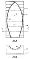
- a female die 11 of cage construction is shown.
- This die consists of a plurality of longitudinally extending ribs 12 each spaced sufficiently from one another so as to allow air to pass through without permitting the deformation of the sheet metal 13 into the voids 15 between said ribs.
- the ribs are supported in the correct shape by a plurality of upstanding webs 16 extending transversely of the mould and shaped to cradle the die.
- the webs 16 are mounted on a heavy base 17 to provide a rigid robust construction.
- the ribs would be typically of 20mm x 20mm cross sectored bright steel strip with approximately 2mm space between each metal rib.
- the die is preferably of fully welded construction and designed structurally to withstand multiple uses. The die would for preference be located in an isolated environment and mounted in a pit of suitable size and uniformly supported with gravel or blue metal (typically 14-20mm round) and sealed in place with a reinforced concrete cap.
- the use of the method according to the invention in the production of aluminium boat hulls enables economic, low volume production lines to be established.
- inexpensive mild steel dies can be used the cost of these dies can be economically amortised over relatively low production volumes and further these dies can be readily modified to cope with hull design changes.
- the process provides the added advantage of requiring few skilled trademen to produce a uniform product of high dimensional accuracy and precision.
- production line techniques enables the application of other advanced manufacturing techniques such as robotics for welding or spray painting.
Claims (8)
le moule (11) est de construction en forme de cage comportant des espaces (15) et définissant une enveloppe de la forme voulue ;
l'étape (3) comprend le revêtement du moule (11) par la tôle (13) ;
entre les étapes (iii) et (iv), le procédé comprend en outre l'étape consistant à remplir de milieu liquide le moule revêtu ; et
au cours de l'étape (iv), la tôle (13) prend la forme définie par l'enveloppe du moule (11), tandis que l'air piégé entre la tôle (13) et l'enveloppe du moule (11) s'échappe par les espaces (15) de la construction en forme de cage sans que l'action d'un vide soit nécessaire.
Priority Applications (1)
| Application Number | Priority Date | Filing Date | Title |
|---|---|---|---|
| AT88903745T ATE77772T1 (de) | 1987-04-15 | 1988-04-15 | Formungsverfahren fuer metalle. |
Applications Claiming Priority (2)
| Application Number | Priority Date | Filing Date | Title |
|---|---|---|---|
| AU1467/87 | 1987-04-15 | ||
| AUPI146787 | 1987-04-15 |
Publications (3)
| Publication Number | Publication Date |
|---|---|
| EP0371018A1 EP0371018A1 (fr) | 1990-06-06 |
| EP0371018A4 EP0371018A4 (en) | 1990-09-26 |
| EP0371018B1 true EP0371018B1 (fr) | 1992-07-01 |
Family
ID=3772119
Family Applications (1)
| Application Number | Title | Priority Date | Filing Date |
|---|---|---|---|
| EP88903745A Expired - Lifetime EP0371018B1 (fr) | 1987-04-15 | 1988-04-15 | Procede de matrisage des metaux |
Country Status (7)
| Country | Link |
|---|---|
| US (1) | US5016457A (fr) |
| EP (1) | EP0371018B1 (fr) |
| JP (1) | JPH02503403A (fr) |
| AT (1) | ATE77772T1 (fr) |
| AU (1) | AU615193B2 (fr) |
| DE (1) | DE3872523T2 (fr) |
| WO (1) | WO1988007899A1 (fr) |
Cited By (7)
| Publication number | Priority date | Publication date | Assignee | Title |
|---|---|---|---|---|
| US8047036B2 (en) | 2005-06-03 | 2011-11-01 | Magna International Inc. | Device and method for explosion forming |
| US8650921B2 (en) | 2006-08-11 | 2014-02-18 | Cosma Engineering Europe Ag | Method and device for explosion forming |
| US8713982B2 (en) | 2008-01-31 | 2014-05-06 | Magna International Inc. | Device for explosive forming |
| US8875553B2 (en) | 2007-02-14 | 2014-11-04 | Cosma Engineering Europe Ag | Method and mould arrangement for explosion forming |
| US8939743B2 (en) | 2007-08-02 | 2015-01-27 | Cosma Engineering Europe Ag | Device for supplying a fluid for explosion forming |
| US9393606B2 (en) | 2007-05-22 | 2016-07-19 | Cosma Engineering Europe Ag | Ignition device for explosive forming |
| US9737922B2 (en) | 2007-02-14 | 2017-08-22 | Magna International Inc. | Explosion forming system |
Families Citing this family (1)
| Publication number | Priority date | Publication date | Assignee | Title |
|---|---|---|---|---|
| US7013694B1 (en) | 2004-05-14 | 2006-03-21 | Steven Don Sims | Portable, metal bending apparatus |
Family Cites Families (15)
| Publication number | Priority date | Publication date | Assignee | Title |
|---|---|---|---|---|
| SE115846C1 (fr) * | 1940-03-08 | 1946-02-19 | ||
| DE1163280B (de) * | 1960-07-01 | 1964-02-20 | Mak Maschb Kiel G M B H | Vorrichtung zum Verformen von Blech unter Schockwirkung |
| DE1134651B (de) * | 1960-07-01 | 1962-08-16 | Mak Maschb Kiel G M B H | Vorrichtung zum Verformen von Blechen unter Schockwirkung |
| US3236080A (en) * | 1961-07-10 | 1966-02-22 | Continental Can Co | Procedure and device for the shaping of containers, container bodies or container parts, from a thin-walled first shape |
| US3164941A (en) * | 1962-08-03 | 1965-01-12 | Int Harvester Co | Flexible cotton picker spindle |
| US3238753A (en) * | 1962-11-05 | 1966-03-08 | Lockheed Aircraft Corp | Stretch forming apparatus and method |
| DE1218986B (de) * | 1962-12-21 | 1966-06-16 | Wmf Wuerttemberg Metallwaren | Verfahen und Platine zur Herstellung von Hohlkoerpern oder aehnlichen Formteilen ausBlech durch Hochenergieumformung |
| SU359893A1 (ru) * | 1963-06-10 | 1973-04-05 | Л. А. Юткин , Л. И. Гольцова | Матрица для импульсного формообразования |
| DE1777208A1 (de) * | 1968-09-25 | 1971-04-01 | Hertel Heinrich Prof Dr Ing | Vorrichtung zur Hochleistungsumformung von Werkstuecken,insbesondere aus Blech,mit Hilfe von Schockwirkungsmitteln |
| DE1777207A1 (de) * | 1968-09-25 | 1971-04-01 | Hertel Heinrich Prof Dr Ing | Vorrichtung zur Hochleistungsumformung von Werkstuecken,insbesondere aus Blech,mit Hilfe von Schockwirkungsmitteln |
| US3757411A (en) * | 1971-11-04 | 1973-09-11 | J Douglas | Manufacture of deep, narrow, hollow articles |
| FR2397245A1 (fr) * | 1977-07-13 | 1979-02-09 | Secathen Sa | Procede de fabrication de toles ondulees metalliques presentant un ou plusieurs bords droits, et toles ainsi obtenues |
| AU4882779A (en) * | 1978-07-12 | 1980-01-17 | Miell, A.L. | Boat construction |
| JPS60231530A (ja) * | 1984-04-27 | 1985-11-18 | Hiroshimaken | 小型船体の成形法 |
| JPH088896B2 (ja) * | 1993-06-30 | 1996-01-31 | 株式会社共和工業所 | 焼成調理装置 |
-
1988
- 1988-04-15 EP EP88903745A patent/EP0371018B1/fr not_active Expired - Lifetime
- 1988-04-15 DE DE8888903745T patent/DE3872523T2/de not_active Expired - Fee Related
- 1988-04-15 WO PCT/AU1988/000113 patent/WO1988007899A1/fr active IP Right Grant
- 1988-04-15 AT AT88903745T patent/ATE77772T1/de not_active IP Right Cessation
- 1988-04-15 JP JP63503458A patent/JPH02503403A/ja active Pending
- 1988-04-15 AU AU17002/88A patent/AU615193B2/en not_active Ceased
- 1988-12-15 US US07/444,144 patent/US5016457A/en not_active Expired - Fee Related
Cited By (7)
| Publication number | Priority date | Publication date | Assignee | Title |
|---|---|---|---|---|
| US8047036B2 (en) | 2005-06-03 | 2011-11-01 | Magna International Inc. | Device and method for explosion forming |
| US8650921B2 (en) | 2006-08-11 | 2014-02-18 | Cosma Engineering Europe Ag | Method and device for explosion forming |
| US8875553B2 (en) | 2007-02-14 | 2014-11-04 | Cosma Engineering Europe Ag | Method and mould arrangement for explosion forming |
| US9737922B2 (en) | 2007-02-14 | 2017-08-22 | Magna International Inc. | Explosion forming system |
| US9393606B2 (en) | 2007-05-22 | 2016-07-19 | Cosma Engineering Europe Ag | Ignition device for explosive forming |
| US8939743B2 (en) | 2007-08-02 | 2015-01-27 | Cosma Engineering Europe Ag | Device for supplying a fluid for explosion forming |
| US8713982B2 (en) | 2008-01-31 | 2014-05-06 | Magna International Inc. | Device for explosive forming |
Also Published As
| Publication number | Publication date |
|---|---|
| AU1700288A (en) | 1988-11-04 |
| JPH02503403A (ja) | 1990-10-18 |
| DE3872523T2 (de) | 1993-03-11 |
| DE3872523D1 (de) | 1992-08-06 |
| US5016457A (en) | 1991-05-21 |
| AU615193B2 (en) | 1991-09-26 |
| EP0371018A1 (fr) | 1990-06-06 |
| WO1988007899A1 (fr) | 1988-10-20 |
| ATE77772T1 (de) | 1992-07-15 |
| EP0371018A4 (en) | 1990-09-26 |
Similar Documents
| Publication | Publication Date | Title |
|---|---|---|
| US3196533A (en) | Method for forming honeycomb materials | |
| EP0371018B1 (fr) | Procede de matrisage des metaux | |
| US3992835A (en) | Sinusoidal structural element | |
| US3160952A (en) | Method of explosively plating particles on a part | |
| US4004429A (en) | Deep underwater sphere | |
| US10766626B2 (en) | Single-piece extended laminar flow inlet lipskin | |
| EP0324231B1 (fr) | Méthode pour faire une plaque métallique multi-laminaire jointe par explosion | |
| US11020815B2 (en) | Single-piece extended laminar flow inlet lipskin | |
| CA2471066A1 (fr) | Methode de fabrication d'un element de chassis de vehicule par hydroformage a haute vitesse | |
| CA1311159C (fr) | Methode de formage du metal | |
| EP0351154A2 (fr) | Moule revêtu de métal pour objet plastique et son procédé de fabrication | |
| EP3406750A1 (fr) | Pièce en aluminium aérospatial (lipskin) | |
| GB925422A (en) | Explosive forming method and apparatus | |
| US6510720B1 (en) | Hydraulic pressure forming using a self aligning and activating die system | |
| US3849996A (en) | Method and apparatus for positioning a cofferdam | |
| RU2091697C1 (ru) | Способ взрывной резки конструкций и линейный кумулятивный заряд для его осуществления | |
| EP0630308B1 (fr) | Dispositif permettant de gainer des tubes au moyen d'un procede explosif | |
| EP0057308A1 (fr) | Dispositif et procédé pour faire sauter des roches sousmarines | |
| JPS5851777B2 (ja) | レンゾクテキキンゾクチユウゾウイガタ | |
| Schroeder | Explosive forming | |
| JPS589728A (ja) | 爆発成形パネルの製造方法 | |
| CN111940887B (zh) | 环形复合结构爆炸焊接方法 | |
| US3469426A (en) | Explosive formation | |
| Islamoff | Metal-forming techniques | |
| RU2695855C2 (ru) | Способ сварки взрывом металлических листов |
Legal Events
| Date | Code | Title | Description |
|---|---|---|---|
| PUAI | Public reference made under article 153(3) epc to a published international application that has entered the european phase |
Free format text: ORIGINAL CODE: 0009012 |
|
| 17P | Request for examination filed |
Effective date: 19891016 |
|
| AK | Designated contracting states |
Kind code of ref document: A1 Designated state(s): AT BE CH DE FR GB IT LI LU NL SE |
|
| A4 | Supplementary search report drawn up and despatched |
Effective date: 19900807 |
|
| AK | Designated contracting states |
Kind code of ref document: A4 Designated state(s): AT BE CH DE FR GB IT LI LU NL SE |
|
| 17Q | First examination report despatched |
Effective date: 19910306 |
|
| GRAA | (expected) grant |
Free format text: ORIGINAL CODE: 0009210 |
|
| AK | Designated contracting states |
Kind code of ref document: B1 Designated state(s): AT BE CH DE FR GB IT LI LU NL SE |
|
| PG25 | Lapsed in a contracting state [announced via postgrant information from national office to epo] |
Ref country code: LI Effective date: 19920701 Ref country code: CH Effective date: 19920701 Ref country code: BE Effective date: 19920701 Ref country code: AT Effective date: 19920701 |
|
| REF | Corresponds to: |
Ref document number: 77772 Country of ref document: AT Date of ref document: 19920715 Kind code of ref document: T |
|
| ITF | It: translation for a ep patent filed |
Owner name: STUDIO FERRARIO |
|
| RAP2 | Party data changed (patent owner data changed or rights of a patent transferred) |
Owner name: THE RESEARCH FOUNDATION INSTITUTE PTY. LIMITED |
|
| REF | Corresponds to: |
Ref document number: 3872523 Country of ref document: DE Date of ref document: 19920806 |
|
| ET | Fr: translation filed | ||
| REG | Reference to a national code |
Ref country code: CH Ref legal event code: PL |
|
| PG25 | Lapsed in a contracting state [announced via postgrant information from national office to epo] |
Ref country code: LU Free format text: LAPSE BECAUSE OF NON-PAYMENT OF DUE FEES Effective date: 19930430 |
|
| PLBE | No opposition filed within time limit |
Free format text: ORIGINAL CODE: 0009261 |
|
| STAA | Information on the status of an ep patent application or granted ep patent |
Free format text: STATUS: NO OPPOSITION FILED WITHIN TIME LIMIT |
|
| 26N | No opposition filed | ||
| EAL | Se: european patent in force in sweden |
Ref document number: 88903745.3 |
|
| PGFP | Annual fee paid to national office [announced via postgrant information from national office to epo] |
Ref country code: SE Payment date: 19980420 Year of fee payment: 11 Ref country code: GB Payment date: 19980420 Year of fee payment: 11 Ref country code: FR Payment date: 19980420 Year of fee payment: 11 |
|
| PGFP | Annual fee paid to national office [announced via postgrant information from national office to epo] |
Ref country code: DE Payment date: 19980422 Year of fee payment: 11 |
|
| PGFP | Annual fee paid to national office [announced via postgrant information from national office to epo] |
Ref country code: NL Payment date: 19980423 Year of fee payment: 11 |
|
| PG25 | Lapsed in a contracting state [announced via postgrant information from national office to epo] |
Ref country code: GB Free format text: LAPSE BECAUSE OF NON-PAYMENT OF DUE FEES Effective date: 19990415 |
|
| PG25 | Lapsed in a contracting state [announced via postgrant information from national office to epo] |
Ref country code: SE Free format text: LAPSE BECAUSE OF NON-PAYMENT OF DUE FEES Effective date: 19990416 |
|
| PG25 | Lapsed in a contracting state [announced via postgrant information from national office to epo] |
Ref country code: NL Free format text: LAPSE BECAUSE OF NON-PAYMENT OF DUE FEES Effective date: 19991101 |
|
| GBPC | Gb: european patent ceased through non-payment of renewal fee |
Effective date: 19990415 |
|
| PG25 | Lapsed in a contracting state [announced via postgrant information from national office to epo] |
Ref country code: FR Free format text: LAPSE BECAUSE OF NON-PAYMENT OF DUE FEES Effective date: 19991231 |
|
| NLV4 | Nl: lapsed or anulled due to non-payment of the annual fee |
Effective date: 19991101 |
|
| EUG | Se: european patent has lapsed |
Ref document number: 88903745.3 |
|
| REG | Reference to a national code |
Ref country code: FR Ref legal event code: ST |
|
| PG25 | Lapsed in a contracting state [announced via postgrant information from national office to epo] |
Ref country code: DE Free format text: LAPSE BECAUSE OF NON-PAYMENT OF DUE FEES Effective date: 20000201 |
|
| PG25 | Lapsed in a contracting state [announced via postgrant information from national office to epo] |
Ref country code: IT Free format text: LAPSE BECAUSE OF NON-PAYMENT OF DUE FEES Effective date: 20050415 |