EP0371018B1 - A method of forming metal - Google Patents
A method of forming metal Download PDFInfo
- Publication number
- EP0371018B1 EP0371018B1 EP88903745A EP88903745A EP0371018B1 EP 0371018 B1 EP0371018 B1 EP 0371018B1 EP 88903745 A EP88903745 A EP 88903745A EP 88903745 A EP88903745 A EP 88903745A EP 0371018 B1 EP0371018 B1 EP 0371018B1
- Authority
- EP
- European Patent Office
- Prior art keywords
- sheet metal
- mould
- forming
- ribs
- spaces
- Prior art date
- Legal status (The legal status is an assumption and is not a legal conclusion. Google has not performed a legal analysis and makes no representation as to the accuracy of the status listed.)
- Expired - Lifetime
Links
Images


Classifications
-
- B—PERFORMING OPERATIONS; TRANSPORTING
- B21—MECHANICAL METAL-WORKING WITHOUT ESSENTIALLY REMOVING MATERIAL; PUNCHING METAL
- B21D—WORKING OR PROCESSING OF SHEET METAL OR METAL TUBES, RODS OR PROFILES WITHOUT ESSENTIALLY REMOVING MATERIAL; PUNCHING METAL
- B21D26/00—Shaping without cutting otherwise than using rigid devices or tools or yieldable or resilient pads, i.e. applying fluid pressure or magnetic forces
- B21D26/02—Shaping without cutting otherwise than using rigid devices or tools or yieldable or resilient pads, i.e. applying fluid pressure or magnetic forces by applying fluid pressure
- B21D26/06—Shaping without cutting otherwise than using rigid devices or tools or yieldable or resilient pads, i.e. applying fluid pressure or magnetic forces by applying fluid pressure by shock waves
- B21D26/08—Shaping without cutting otherwise than using rigid devices or tools or yieldable or resilient pads, i.e. applying fluid pressure or magnetic forces by applying fluid pressure by shock waves generated by explosives, e.g. chemical explosives
-
- Y—GENERAL TAGGING OF NEW TECHNOLOGICAL DEVELOPMENTS; GENERAL TAGGING OF CROSS-SECTIONAL TECHNOLOGIES SPANNING OVER SEVERAL SECTIONS OF THE IPC; TECHNICAL SUBJECTS COVERED BY FORMER USPC CROSS-REFERENCE ART COLLECTIONS [XRACs] AND DIGESTS
- Y10—TECHNICAL SUBJECTS COVERED BY FORMER USPC
- Y10S—TECHNICAL SUBJECTS COVERED BY FORMER USPC CROSS-REFERENCE ART COLLECTIONS [XRACs] AND DIGESTS
- Y10S72/00—Metal deforming
- Y10S72/706—Explosive
-
- Y—GENERAL TAGGING OF NEW TECHNOLOGICAL DEVELOPMENTS; GENERAL TAGGING OF CROSS-SECTIONAL TECHNOLOGIES SPANNING OVER SEVERAL SECTIONS OF THE IPC; TECHNICAL SUBJECTS COVERED BY FORMER USPC CROSS-REFERENCE ART COLLECTIONS [XRACs] AND DIGESTS
- Y10—TECHNICAL SUBJECTS COVERED BY FORMER USPC
- Y10T—TECHNICAL SUBJECTS COVERED BY FORMER US CLASSIFICATION
- Y10T29/00—Metal working
- Y10T29/49—Method of mechanical manufacture
- Y10T29/49805—Shaping by direct application of fluent pressure
- Y10T29/49806—Explosively shaping
Definitions
- the present invention relates to forming sheet metal into complex or compound shapes and particularly to the use of High Energy Rate Forming Techniques (HERF) in such a method.
- HERF High Energy Rate Forming Techniques
- the high energy forming techniques of the type under discussion use high explosives to form metal. These techniques normally use water or some other suitable fluid as a transfer medium for the mechanical energy produced by the explosives. It has been found that liquids transmit the mechanical energy generated more efficiently than air. Normally the process happens in an open tank. The charge of high explosive detonates in the water a short distance from the sheet of metal to be formed. The explosion causes pressure waves to transmit momentum to the metal and force it against the surface of a hollow die by plastic deformation.
- the detonation wave that passes through the exploding charge interacts with the water in two ways. First, it creates in a liquid a shock wave that strikes the metal.
- the detonation wave also forms a bubble of compressed gas in the water.
- the bubble expands and contracts repeatedly as it reflects off the surface of the workpiece and sides of the tank, before venting into the air.
- the peak pressure produced by the oscillating bubble is perhaps only 10 to 20 % of the peak shock wave, the bubble's contribution to forming the metal is also significant.
- the gas pressure lasts longer than the initial shock wave.
- the present invention seeks to overcome this problem and provide a method of using the known high energy rate forming techniques without the requirement of applying a vacuum between the mould and the sheet metal to be formed.
- a method of forming sheet metal comprising the steps of:
- the sheet metal when forming large items, may comprise several part formed pieces joined to form a single sheet (see, for example, US-A-3757411).
- the sheets are joined by welding.
- the die is preferably lined inside the sheet metal with a liquid impervious material liner before filling with the liquid medium.
- the mould comprises a plurality of longitudinally extending, closely spaced ribs.
- the inner surface of the mould is coated with a frangible material to provide a smooth surface to the mould by filling the space between the ribs.
- the frangible material is shattered during the deformation process and expelled with trapped air through the spaces between the ribs.
- a mould for use in the method in accordance with the first aspect of the present invention comprising a plurality of longitudinally extending, closely spaced ribs mounted on a cradle formed from a plurality of webs extending transversely of the ribs, wherein the webs are shaped and arranged to support the ribs so as to form the desired internal shape of the mould, and the spacing between the ribs is sufficient to allow the expulsion of air trapped between sheet metal and the mould during deformation of the sheet metal.
- the labour cost and time of construction is substantially greater than the equivalent process of competing fibreglass manufacturers who can lay-up their materials in a female mould and produce uniform smooth hulls repetitively and less expensively. This cost difference is such that metal boats are not an economically viable proposition for round bilge production boats in the 6 - 15 metres, mass market, pleasure or work boat range. Aluminium alloy hulls are even more difficult than steel due to the greater distortion that takes place on welding, requiring a higher level of skilled tradesman.
- tank 1 has mounted therein a die 7.
- the die is supported by container 8 resting on a base 9.
- the metal sheet to be formed 3 is clamped across the opening to the die 7.
- the space between the die and the plate 3 is evacuated by means by vacuum pipe 10 extending from the surface of the die to a vacuum pump external of the tank.
- the tank is filled with water 2 and the explosive 5 with associated detonator 6 is lowered to an appropriate stand-off distance 4 from the upper surface of the plate 3.
- the plate 3 On detonation of the explosive, the plate 3 is forced into contact with the die surface and takes up the shape of the die.
- the vacuum prevents the formation of air bubbles during the plastic deformation of the sheet metal and avoids distortion thereof.
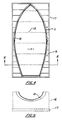
- a female die 11 of cage construction is shown.
- This die consists of a plurality of longitudinally extending ribs 12 each spaced sufficiently from one another so as to allow air to pass through without permitting the deformation of the sheet metal 13 into the voids 15 between said ribs.
- the ribs are supported in the correct shape by a plurality of upstanding webs 16 extending transversely of the mould and shaped to cradle the die.
- the webs 16 are mounted on a heavy base 17 to provide a rigid robust construction.
- the ribs would be typically of 20mm x 20mm cross sectored bright steel strip with approximately 2mm space between each metal rib.
- the die is preferably of fully welded construction and designed structurally to withstand multiple uses. The die would for preference be located in an isolated environment and mounted in a pit of suitable size and uniformly supported with gravel or blue metal (typically 14-20mm round) and sealed in place with a reinforced concrete cap.
- the use of the method according to the invention in the production of aluminium boat hulls enables economic, low volume production lines to be established.
- inexpensive mild steel dies can be used the cost of these dies can be economically amortised over relatively low production volumes and further these dies can be readily modified to cope with hull design changes.
- the process provides the added advantage of requiring few skilled trademen to produce a uniform product of high dimensional accuracy and precision.
- production line techniques enables the application of other advanced manufacturing techniques such as robotics for welding or spray painting.
Abstract
Description
- The present invention relates to forming sheet metal into complex or compound shapes and particularly to the use of High Energy Rate Forming Techniques (HERF) in such a method.
- The high energy forming techniques of the type under discussion use high explosives to form metal. These techniques normally use water or some other suitable fluid as a transfer medium for the mechanical energy produced by the explosives. It has been found that liquids transmit the mechanical energy generated more efficiently than air. Normally the process happens in an open tank. The charge of high explosive detonates in the water a short distance from the sheet of metal to be formed. The explosion causes pressure waves to transmit momentum to the metal and force it against the surface of a hollow die by plastic deformation.
- The detonation wave that passes through the exploding charge interacts with the water in two ways. First, it creates in a liquid a shock wave that strikes the metal. The detonation wave also forms a bubble of compressed gas in the water. The bubble expands and contracts repeatedly as it reflects off the surface of the workpiece and sides of the tank, before venting into the air. Though the peak pressure produced by the oscillating bubble is perhaps only 10 to 20 % of the peak shock wave, the bubble's contribution to forming the metal is also significant. The gas pressure lasts longer than the initial shock wave.
- Many different materials are used in the dies for explosive forming. Inexpensive dies of zinc alloys, epoxy resin or even hard wood are tough enough to make small numbers of products with limited accuracy. Plaster is used for dies where single use of die is sufficient. Reinforced concrete dies, usually resin coated, are an efficient way to make large parts in small numbers. If a manufacturer wishes to make a lot of parts then the dies must be made of ductile iron or special steels which can be reused many times.
- The advantage of these techniques are that large complex or compound curved shapes can be formed without the need for heavy presses and the very expensive conventional metal dies.
- These known techniques (see, for example, DE-A-1218986) form the base for the pre-characterising part of claim 1 and generally require a vacuum to be applied between the mould (die) surface and the sheet metal prior to discharge of the explosive, to remove the air from the space that the metal will ultimately be asked to take up. If this is not done the speed with which the plastic deformation of the sheet metal takes place is so fast as to cause a compressed air bubble to form resulting in the distortion of the finished sheet metal and prevention of it flowing into the desired shape of the female die. The application of such a vacuum is simple when moulding small shapes. However, when large complex shapes are to be produced in a relatively rough mould it is difficult to produce the appropriate vacuum required because of the need to obtain a seal between the workpiece and the die surface. This process also adds costs to the process.
- The present invention seeks to overcome this problem and provide a method of using the known high energy rate forming techniques without the requirement of applying a vacuum between the mould and the sheet metal to be formed.
- According to a first aspect of the present invention, there is provided a method of forming sheet metal, comprising the steps of:
- (i) forming a female mould of the desired shape;
- (ii) placing the mould in supporting means extending therearound;
- (iii) positioning adjacent to the mould the sheet metal to be formed into the desired shape; and
- (iv) detonating one or more explosive charges at predetermined location(s) within a liquid medium to cause deformation of the sheet metal and taking up by the sheet metal of the desired shape defined by the female mould;
characterized in that: the mould is of a cage-like construction having spaces therein and defining an envelope of the desired shape; step (iii) comprises lining the mould with the sheet metal; between steps (iii) and (iv), the method further comprises the step of filling the lined mould with the liquid medium; and, during step (iv), the sheet metal takes up the shape defined by the envelope of the mould, whilst air trapped between the sheet metal and the envelope of the mould escapes through the spaces of the cage-like construction without the need for vacuum assistance. - For preference, when forming large items, the sheet metal may comprise several part formed pieces joined to form a single sheet (see, for example, US-A-3757411). Preferably the sheets are joined by welding. If the sheet metal is not liquid impervious, the die is preferably lined inside the sheet metal with a liquid impervious material liner before filling with the liquid medium. Preferably, the mould comprises a plurality of longitudinally extending, closely spaced ribs.
- In a preferred method, the inner surface of the mould is coated with a frangible material to provide a smooth surface to the mould by filling the space between the ribs. The frangible material is shattered during the deformation process and expelled with trapped air through the spaces between the ribs.
- According to a second aspect of the present invention, there is provided a mould for use in the method in accordance with the first aspect of the present invention, comprising a plurality of longitudinally extending, closely spaced ribs mounted on a cradle formed from a plurality of webs extending transversely of the ribs, wherein the webs are shaped and arranged to support the ribs so as to form the desired internal shape of the mould, and the spacing between the ribs is sufficient to allow the expulsion of air trapped between sheet metal and the mould during deformation of the sheet metal.
- The invention will now be described in relation to its application to the production of moulds for round bilge boats. However, it will be apparent to those skilled in the art that the invention is equally applicable to any application requiring formation of complex or compound curves in sheet metal and the invention is not limited to the particular application described.
- Presently boats are built from sheet metal (mild steel and aluminium alloy) in a production line sense if they are small (less than 6 metres) and do not have complex or compound curves associated with the plating, ie. less attractive "hard-chine" construction. Alternatively if the vessels are large (greater than 15 metres) and are 'one-off', rather than production line models, they are produced from individually shaped plates welded over a preformed set of boat frames, each panel being independently worked to impart the smooth compound curves necessary for the ultimate round bilge hull and then welded in place over the internal framework. These smooth lines often require the application of plastic putty to camouflage the imperfections in shape (e.g. distortion caused by welding plates) thus adding to cost of the final product. The labour cost and time of construction is substantially greater than the equivalent process of competing fibreglass manufacturers who can lay-up their materials in a female mould and produce uniform smooth hulls repetitively and less expensively. This cost difference is such that metal boats are not an economically viable proposition for round bilge production boats in the 6 - 15 metres, mass market, pleasure or work boat range. Aluminium alloy hulls are even more difficult than steel due to the greater distortion that takes place on welding, requiring a higher level of skilled tradesman.
- A preferred embodiment of the invention, by way of example only, will now be described in relation to this particular application and with reference to the accompanying drawings, in which:
- Figure 1 shows a pictorial representation of the prior art method of forming sheet metal into complex shapes using high energy rate forming techniques;
- Figure 2 shows a pictorial perspective representation of the die mould according to the present invention;
- Figure 3 shows a cross-sectional view taken on lines 3-3 of Figure 2 illustrating a portion of the sheet panels and frangible material applied to the inner surface of the mould;
- Figure 4 shows a plan view of the die mould with the preformed, curved panels welded in place; and
- Figure 5 shows an end elevation of one preformed panel prior to fitting.
- Referring to Figure 1 of the drawings, tank 1 has mounted therein a die 7. The die is supported by container 8 resting on a base 9. The metal sheet to be formed 3 is clamped across the opening to the die 7. The space between the die and the
plate 3 is evacuated by means by vacuum pipe 10 extending from the surface of the die to a vacuum pump external of the tank. The tank is filled withwater 2 and the explosive 5 with associateddetonator 6 is lowered to an appropriate stand-off distance 4 from the upper surface of theplate 3. On detonation of the explosive, theplate 3 is forced into contact with the die surface and takes up the shape of the die. The vacuum prevents the formation of air bubbles during the plastic deformation of the sheet metal and avoids distortion thereof. - Referring to Figure 2 of the drawings, a
female die 11 of cage construction is shown. This die consists of a plurality of longitudinally extendingribs 12 each spaced sufficiently from one another so as to allow air to pass through without permitting the deformation of thesheet metal 13 into the voids 15 between said ribs. The ribs are supported in the correct shape by a plurality ofupstanding webs 16 extending transversely of the mould and shaped to cradle the die. Thewebs 16 are mounted on aheavy base 17 to provide a rigid robust construction. The ribs would be typically of 20mm x 20mm cross sectored bright steel strip with approximately 2mm space between each metal rib. The die is preferably of fully welded construction and designed structurally to withstand multiple uses. The die would for preference be located in an isolated environment and mounted in a pit of suitable size and uniformly supported with gravel or blue metal (typically 14-20mm round) and sealed in place with a reinforced concrete cap. - A typical example of the application of the method according to the invention to application of the boat hull would be as follows:
- 1. Coating the inside of the die cage with a smooth plaster of paris 'wash' 14 sufficient to yield a smooth shell of fragile nature. This plaster wash 14 is disposable and replaced between successive uses of the die mould.
- 2. Lining this die of suitable hull shape with preformed, planar curved, half or full width metal panels 18 (typically marine grade Aluminium Alloy [5083-H321]). These
panels 18 may be typically between 1200-1400mm wide and of 5mm thickness in a 10 metre long boat. An example of a typical die surface is depicted in Figure 3. - 3. Clamping the panels along the centre and across the die;
- 4. Internally welding the side seams 19 of the preformed, planar
curved panels 18 using current technology for giving a sound joint in Aluminium plate; These side seams 19 are in contact with the die/mould surface during welding and suffer minimum stress in later forming; - 5. Lining the sheet metal lay-up with a full sized polyethylene liner and filling with water (This step is only necessary if the prewelded shell to be formed into the die shape is not waterproof);
- 6. Lowering a frame into the water onto which are mounted strategically placed and sized charges of high explosive (typically PETN (Pentaeythanol Tetranitrate) detonation cord-Cortex) connected in parallel to detonate instantaneously;
- 7. Detonation of charge, removal of water/plastic to access full formed boat shell. This process may be repeated if imperfections in the skin dictate a second application of the forming energy;
- 8. Frame-up the shell by fitting in metal stringer bulkheads, frames, floors by welding or other suitable fixing means while still supported in the die and then welding on decking, as would a typical fibreglass producer of mass market, round bilge, pleasure boats. Decking may also be advantageously formed using the inventive method.
- The use of the method according to the invention in the production of aluminium boat hulls enables economic, low volume production lines to be established. As inexpensive mild steel dies can be used the cost of these dies can be economically amortised over relatively low production volumes and further these dies can be readily modified to cope with hull design changes. The process provides the added advantage of requiring few skilled trademen to produce a uniform product of high dimensional accuracy and precision. Further the use of production line techniques enables the application of other advanced manufacturing techniques such as robotics for welding or spray painting.
Claims (8)
the mould (11) is of a cage-like construction having spaces (15) therein and defining an envelope of the desired shape;
step (iii) comprises lining the mould (11) with the sheet metal (13);
between steps (iii) and (iv), the method further comprises the step of filling the lined mould with the liquid medium; and,
during step (iv), the sheet metal (13) takes up the shape defined by the envelope of the mould (11), whilst air trapped between the sheet metal (13) and the envelope of the mould (11) escapes through the spaces (15) of the cage-like construction without the need for vacuum assistance.
Priority Applications (1)
| Application Number | Priority Date | Filing Date | Title |
|---|---|---|---|
| AT88903745T ATE77772T1 (en) | 1987-04-15 | 1988-04-15 | FORMING PROCESSES FOR METALS. |
Applications Claiming Priority (2)
| Application Number | Priority Date | Filing Date | Title |
|---|---|---|---|
| AU1467/87 | 1987-04-15 | ||
| AUPI146787 | 1987-04-15 |
Publications (3)
| Publication Number | Publication Date |
|---|---|
| EP0371018A1 EP0371018A1 (en) | 1990-06-06 |
| EP0371018A4 EP0371018A4 (en) | 1990-09-26 |
| EP0371018B1 true EP0371018B1 (en) | 1992-07-01 |
Family
ID=3772119
Family Applications (1)
| Application Number | Title | Priority Date | Filing Date |
|---|---|---|---|
| EP88903745A Expired - Lifetime EP0371018B1 (en) | 1987-04-15 | 1988-04-15 | A method of forming metal |
Country Status (7)
| Country | Link |
|---|---|
| US (1) | US5016457A (en) |
| EP (1) | EP0371018B1 (en) |
| JP (1) | JPH02503403A (en) |
| AT (1) | ATE77772T1 (en) |
| AU (1) | AU615193B2 (en) |
| DE (1) | DE3872523T2 (en) |
| WO (1) | WO1988007899A1 (en) |
Cited By (7)
| Publication number | Priority date | Publication date | Assignee | Title |
|---|---|---|---|---|
| US8047036B2 (en) | 2005-06-03 | 2011-11-01 | Magna International Inc. | Device and method for explosion forming |
| US8650921B2 (en) | 2006-08-11 | 2014-02-18 | Cosma Engineering Europe Ag | Method and device for explosion forming |
| US8713982B2 (en) | 2008-01-31 | 2014-05-06 | Magna International Inc. | Device for explosive forming |
| US8875553B2 (en) | 2007-02-14 | 2014-11-04 | Cosma Engineering Europe Ag | Method and mould arrangement for explosion forming |
| US8939743B2 (en) | 2007-08-02 | 2015-01-27 | Cosma Engineering Europe Ag | Device for supplying a fluid for explosion forming |
| US9393606B2 (en) | 2007-05-22 | 2016-07-19 | Cosma Engineering Europe Ag | Ignition device for explosive forming |
| US9737922B2 (en) | 2007-02-14 | 2017-08-22 | Magna International Inc. | Explosion forming system |
Families Citing this family (1)
| Publication number | Priority date | Publication date | Assignee | Title |
|---|---|---|---|---|
| US7013694B1 (en) | 2004-05-14 | 2006-03-21 | Steven Don Sims | Portable, metal bending apparatus |
Family Cites Families (15)
| Publication number | Priority date | Publication date | Assignee | Title |
|---|---|---|---|---|
| SE115846C1 (en) * | 1940-03-08 | 1946-02-19 | ||
| DE1163280B (en) * | 1960-07-01 | 1964-02-20 | Mak Maschb Kiel G M B H | Device for deforming sheet metal under the effect of shock |
| DE1134651B (en) * | 1960-07-01 | 1962-08-16 | Mak Maschb Kiel G M B H | Device for deforming sheet metal under the effect of shock |
| US3236080A (en) * | 1961-07-10 | 1966-02-22 | Continental Can Co | Procedure and device for the shaping of containers, container bodies or container parts, from a thin-walled first shape |
| US3164941A (en) * | 1962-08-03 | 1965-01-12 | Int Harvester Co | Flexible cotton picker spindle |
| US3238753A (en) * | 1962-11-05 | 1966-03-08 | Lockheed Aircraft Corp | Stretch forming apparatus and method |
| DE1218986B (en) * | 1962-12-21 | 1966-06-16 | Wmf Wuerttemberg Metallwaren | Process and plate for the production of hollow bodies or similar shaped parts from sheet metal by high-energy forming |
| SU359893A1 (en) * | 1963-06-10 | 1973-04-05 | Л. А. Юткин , Л. И. Гольцова | MATRIX FOR PULSED FORMING |
| DE1777208A1 (en) * | 1968-09-25 | 1971-04-01 | Hertel Heinrich Prof Dr Ing | Device for high-performance forming of workpieces, in particular made of sheet metal, with the aid of shock agents |
| DE1777207A1 (en) * | 1968-09-25 | 1971-04-01 | Hertel Heinrich Prof Dr Ing | Device for high-performance forming of workpieces, in particular made of sheet metal, with the aid of shock agents |
| US3757411A (en) * | 1971-11-04 | 1973-09-11 | J Douglas | Manufacture of deep, narrow, hollow articles |
| FR2397245A1 (en) * | 1977-07-13 | 1979-02-09 | Secathen Sa | Process deforming plane metal sheet into corrugated form - uses controlled explosion in water to push sheet onto matrix with vacuum in voids |
| AU4882779A (en) * | 1978-07-12 | 1980-01-17 | Miell, A.L. | Boat construction |
| JPS60231530A (en) * | 1984-04-27 | 1985-11-18 | Hiroshimaken | Forming of small-sized hull |
| JPH088896B2 (en) * | 1993-06-30 | 1996-01-31 | 株式会社共和工業所 | Baking equipment |
-
1988
- 1988-04-15 EP EP88903745A patent/EP0371018B1/en not_active Expired - Lifetime
- 1988-04-15 WO PCT/AU1988/000113 patent/WO1988007899A1/en active IP Right Grant
- 1988-04-15 AU AU17002/88A patent/AU615193B2/en not_active Ceased
- 1988-04-15 AT AT88903745T patent/ATE77772T1/en not_active IP Right Cessation
- 1988-04-15 DE DE8888903745T patent/DE3872523T2/en not_active Expired - Fee Related
- 1988-04-15 JP JP63503458A patent/JPH02503403A/en active Pending
- 1988-12-15 US US07/444,144 patent/US5016457A/en not_active Expired - Fee Related
Cited By (7)
| Publication number | Priority date | Publication date | Assignee | Title |
|---|---|---|---|---|
| US8047036B2 (en) | 2005-06-03 | 2011-11-01 | Magna International Inc. | Device and method for explosion forming |
| US8650921B2 (en) | 2006-08-11 | 2014-02-18 | Cosma Engineering Europe Ag | Method and device for explosion forming |
| US8875553B2 (en) | 2007-02-14 | 2014-11-04 | Cosma Engineering Europe Ag | Method and mould arrangement for explosion forming |
| US9737922B2 (en) | 2007-02-14 | 2017-08-22 | Magna International Inc. | Explosion forming system |
| US9393606B2 (en) | 2007-05-22 | 2016-07-19 | Cosma Engineering Europe Ag | Ignition device for explosive forming |
| US8939743B2 (en) | 2007-08-02 | 2015-01-27 | Cosma Engineering Europe Ag | Device for supplying a fluid for explosion forming |
| US8713982B2 (en) | 2008-01-31 | 2014-05-06 | Magna International Inc. | Device for explosive forming |
Also Published As
| Publication number | Publication date |
|---|---|
| DE3872523D1 (en) | 1992-08-06 |
| DE3872523T2 (en) | 1993-03-11 |
| EP0371018A1 (en) | 1990-06-06 |
| AU1700288A (en) | 1988-11-04 |
| EP0371018A4 (en) | 1990-09-26 |
| ATE77772T1 (en) | 1992-07-15 |
| WO1988007899A1 (en) | 1988-10-20 |
| AU615193B2 (en) | 1991-09-26 |
| JPH02503403A (en) | 1990-10-18 |
| US5016457A (en) | 1991-05-21 |
Similar Documents
| Publication | Publication Date | Title |
|---|---|---|
| US3196533A (en) | Method for forming honeycomb materials | |
| EP0371018B1 (en) | A method of forming metal | |
| US4025996A (en) | Sinusoidal structural element | |
| US3992835A (en) | Sinusoidal structural element | |
| US3160952A (en) | Method of explosively plating particles on a part | |
| US4004429A (en) | Deep underwater sphere | |
| US10766626B2 (en) | Single-piece extended laminar flow inlet lipskin | |
| EP0324231B1 (en) | Improved method of making explosively bonded multi-laminar composite metal plate | |
| CA2471066A1 (en) | Method of manufacturing a vehicle frame component by high velocity hydroforming | |
| CA1311159C (en) | Method of forming metal | |
| EP0351154A2 (en) | Metal-coated plastic product mould and procedure for manufacturing the same | |
| EP3406750B1 (en) | Single-piece extended laminar flow inlet lipskin | |
| GB925422A (en) | Explosive forming method and apparatus | |
| US6510720B1 (en) | Hydraulic pressure forming using a self aligning and activating die system | |
| GB2108030A (en) | Joining metal elements by explosion | |
| US3849996A (en) | Method and apparatus for positioning a cofferdam | |
| RU2091697C1 (en) | Method of blast cutting of metalworks and line shaped charge for its realization | |
| EP0630308B1 (en) | A device for cladding tubes by means of an explosive process | |
| EP0057308A1 (en) | Apparatus and method of blasting undersea rocks | |
| JPS5851777B2 (en) | Renzokuteki Kinzokuchi Yuzo Igata | |
| RU2237558C2 (en) | Method for cladding by explosion welding | |
| Schroeder | Explosive forming | |
| JPS589728A (en) | Manufacture of explosive formed panel | |
| US3469426A (en) | Explosive formation | |
| Islamoff | Metal-forming techniques |
Legal Events
| Date | Code | Title | Description |
|---|---|---|---|
| PUAI | Public reference made under article 153(3) epc to a published international application that has entered the european phase |
Free format text: ORIGINAL CODE: 0009012 |
|
| 17P | Request for examination filed |
Effective date: 19891016 |
|
| AK | Designated contracting states |
Kind code of ref document: A1 Designated state(s): AT BE CH DE FR GB IT LI LU NL SE |
|
| A4 | Supplementary search report drawn up and despatched |
Effective date: 19900807 |
|
| AK | Designated contracting states |
Kind code of ref document: A4 Designated state(s): AT BE CH DE FR GB IT LI LU NL SE |
|
| 17Q | First examination report despatched |
Effective date: 19910306 |
|
| GRAA | (expected) grant |
Free format text: ORIGINAL CODE: 0009210 |
|
| AK | Designated contracting states |
Kind code of ref document: B1 Designated state(s): AT BE CH DE FR GB IT LI LU NL SE |
|
| PG25 | Lapsed in a contracting state [announced via postgrant information from national office to epo] |
Ref country code: LI Effective date: 19920701 Ref country code: CH Effective date: 19920701 Ref country code: BE Effective date: 19920701 Ref country code: AT Effective date: 19920701 |
|
| REF | Corresponds to: |
Ref document number: 77772 Country of ref document: AT Date of ref document: 19920715 Kind code of ref document: T |
|
| ITF | It: translation for a ep patent filed |
Owner name: STUDIO FERRARIO |
|
| RAP2 | Party data changed (patent owner data changed or rights of a patent transferred) |
Owner name: THE RESEARCH FOUNDATION INSTITUTE PTY. LIMITED |
|
| REF | Corresponds to: |
Ref document number: 3872523 Country of ref document: DE Date of ref document: 19920806 |
|
| ET | Fr: translation filed | ||
| REG | Reference to a national code |
Ref country code: CH Ref legal event code: PL |
|
| PG25 | Lapsed in a contracting state [announced via postgrant information from national office to epo] |
Ref country code: LU Free format text: LAPSE BECAUSE OF NON-PAYMENT OF DUE FEES Effective date: 19930430 |
|
| PLBE | No opposition filed within time limit |
Free format text: ORIGINAL CODE: 0009261 |
|
| STAA | Information on the status of an ep patent application or granted ep patent |
Free format text: STATUS: NO OPPOSITION FILED WITHIN TIME LIMIT |
|
| 26N | No opposition filed | ||
| EAL | Se: european patent in force in sweden |
Ref document number: 88903745.3 |
|
| PGFP | Annual fee paid to national office [announced via postgrant information from national office to epo] |
Ref country code: SE Payment date: 19980420 Year of fee payment: 11 Ref country code: GB Payment date: 19980420 Year of fee payment: 11 Ref country code: FR Payment date: 19980420 Year of fee payment: 11 |
|
| PGFP | Annual fee paid to national office [announced via postgrant information from national office to epo] |
Ref country code: DE Payment date: 19980422 Year of fee payment: 11 |
|
| PGFP | Annual fee paid to national office [announced via postgrant information from national office to epo] |
Ref country code: NL Payment date: 19980423 Year of fee payment: 11 |
|
| PG25 | Lapsed in a contracting state [announced via postgrant information from national office to epo] |
Ref country code: GB Free format text: LAPSE BECAUSE OF NON-PAYMENT OF DUE FEES Effective date: 19990415 |
|
| PG25 | Lapsed in a contracting state [announced via postgrant information from national office to epo] |
Ref country code: SE Free format text: LAPSE BECAUSE OF NON-PAYMENT OF DUE FEES Effective date: 19990416 |
|
| PG25 | Lapsed in a contracting state [announced via postgrant information from national office to epo] |
Ref country code: NL Free format text: LAPSE BECAUSE OF NON-PAYMENT OF DUE FEES Effective date: 19991101 |
|
| GBPC | Gb: european patent ceased through non-payment of renewal fee |
Effective date: 19990415 |
|
| PG25 | Lapsed in a contracting state [announced via postgrant information from national office to epo] |
Ref country code: FR Free format text: LAPSE BECAUSE OF NON-PAYMENT OF DUE FEES Effective date: 19991231 |
|
| NLV4 | Nl: lapsed or anulled due to non-payment of the annual fee |
Effective date: 19991101 |
|
| EUG | Se: european patent has lapsed |
Ref document number: 88903745.3 |
|
| REG | Reference to a national code |
Ref country code: FR Ref legal event code: ST |
|
| PG25 | Lapsed in a contracting state [announced via postgrant information from national office to epo] |
Ref country code: DE Free format text: LAPSE BECAUSE OF NON-PAYMENT OF DUE FEES Effective date: 20000201 |
|
| PG25 | Lapsed in a contracting state [announced via postgrant information from national office to epo] |
Ref country code: IT Free format text: LAPSE BECAUSE OF NON-PAYMENT OF DUE FEES Effective date: 20050415 |