EP0370876A1 - Device for mounting a demagnetization coil of a television receiver - Google Patents
Device for mounting a demagnetization coil of a television receiver Download PDFInfo
- Publication number
- EP0370876A1 EP0370876A1 EP89403169A EP89403169A EP0370876A1 EP 0370876 A1 EP0370876 A1 EP 0370876A1 EP 89403169 A EP89403169 A EP 89403169A EP 89403169 A EP89403169 A EP 89403169A EP 0370876 A1 EP0370876 A1 EP 0370876A1
- Authority
- EP
- European Patent Office
- Prior art keywords
- fixing
- loop
- foot
- ray tube
- hooks
- Prior art date
- Legal status (The legal status is an assumption and is not a legal conclusion. Google has not performed a legal analysis and makes no representation as to the accuracy of the status listed.)
- Granted
Links
- 230000005347 demagnetization Effects 0.000 title claims abstract description 13
- 210000002105 tongue Anatomy 0.000 description 6
- 239000000463 material Substances 0.000 description 2
- 238000005452 bending Methods 0.000 description 1
- 210000005069 ears Anatomy 0.000 description 1
- 238000009434 installation Methods 0.000 description 1
- 238000000465 moulding Methods 0.000 description 1
- 238000010079 rubber tapping Methods 0.000 description 1
Images
Classifications
-
- H—ELECTRICITY
- H01—ELECTRIC ELEMENTS
- H01J—ELECTRIC DISCHARGE TUBES OR DISCHARGE LAMPS
- H01J29/00—Details of cathode-ray tubes or of electron-beam tubes of the types covered by group H01J31/00
- H01J29/003—Arrangements for eliminating unwanted electromagnetic effects, e.g. demagnetisation arrangements, shielding coils
-
- H—ELECTRICITY
- H01—ELECTRIC ELEMENTS
- H01J—ELECTRIC DISCHARGE TUBES OR DISCHARGE LAMPS
- H01J2229/00—Details of cathode ray tubes or electron beam tubes
- H01J2229/0007—Elimination of unwanted or stray electromagnetic effects
- H01J2229/0046—Preventing or cancelling fields within the enclosure
- H01J2229/0053—Demagnetisation
Definitions
- the present invention relates to a device for fixing a television demagnetization loop.
- the subject of the present invention is a device for fixing a demagnetization loop of a cathode-ray tube of a television set, a device which is simple and inexpensive to produce, and which makes it possible to automate the optimal fixing of the loop, without requiring manual intervention during or after fixing, this device does not depend on the dimensions of the cathode ray tube.
- the demagnetization loop fixing device comprises, for each fixing point of the loop, a workpiece - support comprising at least one hook, workpiece support mounted free to rotate.
- the fixing points are preferably located near the four corners of the cathode ray tube slab.
- these four fixing points are the fixing screws of the cathode ray tube in the cabinet of the television set.
- the fixing devices are mounted to rotate freely on the head of the tube fixing screws.
- the support piece which is advantageously molded in plastic material, comprises two hooks formed on a cross member symmetrically with respect to the junction of this cross member with a support bracket whose foot comprises means allowing it to be fixed, free to rotate, at the attachment point of the loop.
- the demagnetization loop fixing device 1 shown in the drawing is mounted on the head 2 of a screw 3 for fixing the cathode-ray tube (not shown).
- This screw 3 for example of the self-tapping type, passes through the hole of a fixing ear 4 (partially shown in FIG. 2) formed or welded on the anti-implosion belt of the cathode ray tube, and is screwed into a suitable location in the front of the TV.
- the anti-implosion belt has four such fixing ears located approximately on the diagonals of the slab of the cathode-ray tube on which it is placed.
- the head of a cathode ray tube fixing screw generally has the shape of a hexagonal block.
- this screw is modified as follows.
- This extension 7 has the shape of a grooved rod.
- the demagnetization loop fixing device proper consists essentially of a foot 9, a bracket 10 formed on the foot 9, a cross member 11 formed at the end of the bracket 10, two hook devices 12,13 formed at the ends of the cross member 11, and of a guide bar 14 formed on the foot 9. All of these elements of the device 1 are preferably made by molding of plastic material.
- the foot 9 has the shape of a substantially square plate whose central zone 15 is slightly convex (as seen from the stem 10), is circular in shape, has a reduced thickness, and has an axial hole whose diameter is substantially equal to the diameter of the part 7A of the extension 7.
- the area 15 of the foot 9 is split crosswise by two diametrical slots perpendicular to each other, thus delimiting four circular sectors.
- the zone 15 thus forms a retaining ring for fixing the device 1 to the extension 7 of the screw 3. It suffices to force the device 1 onto the extension 7, the grooves 8 causing the four circular sectors of the zone 15 to bend.
- the bracket 10 is formed in the middle of one of the sides of the foot 9, perpendicular to this foot.
- the cross member 11, formed at the end of the bracket 10, consists of two identical arms 11A, 11B arranged symmetrically with respect to the bracket 10, perpendicular to the latter.
- the hook devices 12, 13 each essentially comprise a body 16, 17, respectively, in the form of a rectangular bar, a hook 18, 19 respectively, formed at the end of the bar near its connection with the arm 11A, 11B, and a support tab 20,21, respectively, formed at the other end of the bar.
- the bars 16,17 are parallel to the bracket 10, directed towards the foot 9, and their length is substantially equal to that of the bracket 10.
- the bars 16,17 and the arms 11A, 11B are coplanar.
- the hooks 18,19 are in the form of folded tabs. These tongues comprise a flat part 18A, 19A connected by a bent part to the end of the corresponding bar 16, 17, on the side of the junction of the latter with the arm 11A, 11B respectively.
- the flat parts 18A, 19A make an angle of about 30 to 50 ° with the plane of the bars 16, 17, and are directed approximately towards the junction between the foot 9 and the bar 14.
- the length of the flat parts 18A, 19A is equal or slightly less than half the length of the bars 16,17.
- the respective dimensions of the flat parts 18A, 19A of the bars 16, 17 and the value of the angle formed between said flat parts and the bars are a function of the diameter of the cable 1A, forming the demagnetization loop, and of the space which is has in the cabinetry of the TV.
- the length of the bars 16.17 is approximately 25 mm
- the length of the flat parts 18A, 19A of approximately 10 mm and that of their angle relative to the plane of the bars 16.17 of approximately 40 ° for a 1A cable with a diameter of approximately 6 to 10 mm.
- the support tongues 20,21 are formed in the extension of the bars 16,17, their ends being bent at 90 ° opposite to the screw 3.
- the length of these tongues 20,21 is such that when the device 1 in place on the head 2 of the screw 3 and that this screw is screwed in place to fix the cathode ray tube, the ends 20A, 21A of these tongues are just in contact with the ear 4.
- the length of the bar 14 is substantially equal to that of the bars 16,17.
- This bar 14 has a first rectilinear part 14A parallel to the bracket 10, which extends approximately up to the height of the end 18B, 19B of the hooks 18,19, and a second part 14B, also rectilinear and parallel to the bracket 10, making an angle of about 10 to 20 ° with the first part, this second part deviating from the bracket 10.
- the junction between the parts 14A and 14B is referenced 14C.
- the narrowest part of this opening 22 is located between the junction 14C and the ends 18B, 19B of the parts 18A, 19A.
- the width L of this narrowest part is slightly less (about 1 to 3 mm) than the diameter of the cable lA.
- the loop demagnetization can be simply introduced by an automaton in these four fixing devices without having to be positioned with exactitude, and places itself in the correct position, that is to say symmetrically with respect to the a xes 0x, Oy of the screen, as close as possible to the anti-implosion belt, and with sufficient tension of the buckle.
- the parts 1 of the invention are standard whatever the type and size of the cathode ray tube, the fixing screws 3 being standard.
Landscapes
- Physics & Mathematics (AREA)
- Electromagnetism (AREA)
- Devices For Indicating Variable Information By Combining Individual Elements (AREA)
- Clamps And Clips (AREA)
- Video Image Reproduction Devices For Color Tv Systems (AREA)
Abstract
Pour fixer une boucle de démagnétisation de téléviseur, on utilise des pièces (1) à crochets (18,19) montés libres en rotation sur les têtes des vis de fixation (1) du tube cathodique.To fix a TV demagnetization loop, use is made of parts (1) with hooks (18,19) mounted to rotate freely on the heads of the fixing screws (1) of the cathode ray tube.
Description
La présente invention se rapporte à un dispositif de fixation de boucle de démagnétisation de téléviseur.The present invention relates to a device for fixing a television demagnetization loop.
Pour fixer une boucle de démagnétisation, on utilise généralement des dispositifs à ligatures élastiques. La mise en place de ces dispositifs connus doit se faire manuellement, ce qui ne permet pas toujours de disposer correctement la boucle par rapport au tube.To fix a demagnetization loop, elastic ligature devices are generally used. The establishment of these known devices must be done manually, which does not always allow to correctly arrange the loop relative to the tube.
La présente invention a pour objet un dispositif de fixation de boucle de démagnétisation de tube cathodique de téléviseur, dispositif qui soit simple et peu onéreux à réaliser, et qui permette d'automatiser la fixation optimale de la boucle, sans nécessiter d'intervention manuelle pendant ou après la fixation, ce dispositif ne dépendant pas des dimensions du tube cathodique.The subject of the present invention is a device for fixing a demagnetization loop of a cathode-ray tube of a television set, a device which is simple and inexpensive to produce, and which makes it possible to automate the optimal fixing of the loop, without requiring manual intervention during or after fixing, this device does not depend on the dimensions of the cathode ray tube.
Selon l'invention, le dispositif de fixation de boucle de démagnétisation comprend, pour chaque point de fixation de la boucle une pièce - support comportant au moins un crochet, pièce-support montée libre en rotation. Les points de fixation sont situés de préférence près des quatre coins de la dalle du tube cathodique. De préférence, ces quatre points de fixation sont les vis de fixation du tube cathodique dans l'ébénisterie du téléviseur. De façon avantageuse, les dispositifs de fixation sont montés libres en rotation sur la tête des vis de fixation du tube. Selon un mode de réalisation de l'invention, la pièce-support, qui est avantageusement moulée en matière plastique, comporte deux crochets formés sur une traverse symétriquement par rapport à la jonction de cette traverse avec une potence de support dont le pied comporte des moyens permettant de le fixer, libre en rotation, au point de fixation de la boucle.According to the invention, the demagnetization loop fixing device comprises, for each fixing point of the loop, a workpiece - support comprising at least one hook, workpiece support mounted free to rotate. The fixing points are preferably located near the four corners of the cathode ray tube slab. Preferably, these four fixing points are the fixing screws of the cathode ray tube in the cabinet of the television set. Advantageously, the fixing devices are mounted to rotate freely on the head of the tube fixing screws. According to one embodiment of the invention, the support piece, which is advantageously molded in plastic material, comprises two hooks formed on a cross member symmetrically with respect to the junction of this cross member with a support bracket whose foot comprises means allowing it to be fixed, free to rotate, at the attachment point of the loop.
La présente invention sera mieux comprise à la lecture de la description détaillée d'un mode de réalisation, pris comme exemple non limitatif, et illustré par le dessin annexé sur lequel :
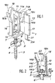
- - la figure 1 est une vue éclatée en perspective d'un dispositif de fixation conforme à l'invention, et
- - la figure 2 est une vue en coupe axiale du dispositif de la figure 1, en position montée.
- FIG. 1 is an exploded perspective view of a fixing device according to the invention, and
- - Figure 2 is an axial sectional view of the device of Figure 1, in the assembled position.
Le dispositif 1 de fixation de boucle de démagnétisation représenté sur le dessin est monté sur la tête 2 d'une vis 3 de fixation de tube cathodique (non représenté). Cette vis 3, par exemple du type autotaraudeuse, passe dans le trou d'une oreille de fixation 4 (partiellement représentée en figure 2) formée ou soudée sur la ceinture anti-implosion du tube cathodique, et est vissée dans un emplacement approprié de la façade du téléviseur. Habituellement, la ceinture anti-implosion comporte quatre telles oreilles de fixation se trouvant à peu près sur les diagonales de la dalle du tube cathodique sur laquelle elle est mise en place. La fixation du tube cathodique dans le coffret du téléviseur étant bien connue en soi, ne sera pas décrite plus en détail.The demagnetization loop fixing device 1 shown in the drawing is mounted on the
La tête d'une vis de fixation de tube cathodique a généralement une forme de pavé hexagonal. Pour pouvoir monter le dispositif 1 sur une vis de fixation de tube cathodique, on modifie cette vis de la façon suivante. On forme sur la tête hexagonale 5 à l'opposé du corps de vis 6 un prolongement axial 7 de faible longueur, par exemple d'une longueur d'environ 5 à 10 mm. Ce prolongement 7 a la forme d'une tige cannelée.The head of a cathode ray tube fixing screw generally has the shape of a hexagonal block. In order to be able to mount the device 1 on a cathode-tube fixing screw, this screw is modified as follows. An
Le dispositif de fixation de boucle de démagnétisation proprement dit se compose essentiellement d'un pied 9 , d' une potence 10 formée sur le pied 9, d'une traverse 11 formée à l'extrémité de la potence 10, de deux dispositifs de crochets 12,13 formés aux extrémités de la traverse 11, et d'une barrette de guidage 14 formée sur le pied 9. L'ensemble de ces éléments du dispositif 1 est, de préférence, réalisé par moulage de matière plastique.The demagnetization loop fixing device proper consists essentially of a foot 9, a
Le pied 9 a la forme d'une plaque de forme sensiblement carrée dont la zone centrale 15 est légèrement convexe (telle que vue de la potence 10), est de forme circulaire, a une épaisseur réduite, et comporte un trou axial dont le diamètre est sensiblement égal au diamètre de la partie 7A du prolongement 7. La zone 15 du pied 9 est fendue en croix par deux fentes diamétrales perpendiculaires entre elles, délimitant ainsi quatre secteurs circulaires. La zone 15 forme ainsi un circlips de fixation du dispositif 1 sur le prolongement 7 de la vis 3. Il suffit d'enfoncer à force le dispositif 1 sur le prolongement 7, les cannelures 8 faisant fléchir les quatre secteurs circulaires de la zone 15.The foot 9 has the shape of a substantially square plate whose
La potence 10 est formée au milieu de l'un des côtés du pied 9, perpendiculairement à ce pied. La traverse 11, formée à l'extrémité de la potence 10, se compose de deux bras identiques 11A,11B disposés symétriquement par rapport à la potence 10, perpendiculairement à celle-ci.The
Les dispositifs de crochets 12,13 comportent chacun essentiellement un corps 16,17, respectivement, en forme de barrette rectangulaire, un crochet 18,19 respectivement, formé à l'extrémité de la barrette près de sa liaison avec le bras 11A,11B, et une languette d'appui 20,21, respectivement, formée à l'autre extrémité de la barrette.The
Les barrettes 16,17 sont parallèles à la potence 10, dirigées vers le pied 9, et leur longueur est sensiblement égale à celle de la potence 10. Les barrettes 16,17 et les bras 11A, 11B sont coplanaires.The
Les crochets 18,19 sont en forme de languettes repliées. Ces languettes comportent une partie plane 18A, 19A reliée par une partie coudée à l'extrémité de la barrette 16,17 correspondante, du côté de la jonction de celle-ci avec le bras 11A, 11B respectivement. Les parties planes 18A, 19A font un angle d'environ 30 à 50° avec le plan des barrettes 16,17, et sont dirigées à peu près vers la jonction entre le pied 9 et la barrette 14. La longueur des parties planes 18A,19A est égale ou légèrement inférieure à la moitié de la longueur des barrettes 16,17. Les dimensions respectives des parties planes 18A, 19A des barrettes 16,17 et la valeur de l'angle formé entre lesdites parties planes et les barrettes sont fonction du diamètre du câble 1A, formant la boucle de démagnétisation, et de l'espace dont on dispose dans l'ébénisterie du téléviseur. Pour un exemple de réalisation, la longueur des barrettes 16,17 est d'environ 25 mm, la longueur des parties planes 18A,19A d'environ 10 mm, et celle de leur angle par rapport au plan des barrettes 16,17 d'environ 40° pour un câble 1A d'un diamètre d'environ 6 à 10 mm.The
Les languettes d'appui 20,21 sont formées dans le prolongement des barrettes 16,17, leurs extrémités étant coudées à 90° à l'opposé de la vis 3. La longueur de ces languettes 20,21 est telle que lorsque le dispositif 1 en place sur la tête 2 de la vis 3 et que cette vis est vissée en place pour fixer le tube cathodique, les extrémités 20A,21A de ces languettes soient juste au contact de l'oreille 4.The
La longueur de la barrette 14 est sensiblement égale à celle des barrettes 16,17. Cette barrette 14 comporte une première partie rectiligne 14A parallèle à la potence 10, qui s'étend à peu près jusqu'à la hauteur de l'extrémité18B,19B des crochets 18,19, et une seconde partie 14B, également rectiligne et parallèle à la potence 10, faisant un angle d'environ 10 à 20° avec la première partie, cette seconde partie s'écartant de la potence 10. La jonction entre les parties 14A et 14B est référencée 14C. On forme ainsi entre la partie 14B et les parties planes 18A,19A une ouverture évasée 22 d'introduction de câble dont l'angle est d'environ 40 à 50°. La partie la plus étroite de cette ouverture 22 se trouve entre la jonction 14C et les extrémités 18B,19B des parties 18A,19A. La largeur L de cette partie la plus étroite est légèrement inférieure (d'environ 1 à 3 mm) au diamètre du câble lA. Ainsi, grâce à l'élasticité de la barrette 14, et des crochets 18,19, dès que l'on fait pénétrer le c&ble 1A dans l'espace 23 compris entre la partie 14A et les barrettes 16,17, ce câble y reste prisonnier. Du fait que la traction exercée sur le câble 1A lors de la mise en place de la boucle de démagnétisation est dirigée à peu près parallèlement aux parties de languettes 18A,19A à l'opposé de la vis 3, le câble 1A vient alors se coincer entre les languettes 18,19 et les barrettes 16,17 respectivement, comme représenté en figure 2. Grâce à la disposition symétrique des crochets 18,19 par rapport à la potence 10 et au pied 9, grâce à la légère flexibllité de la potence 10 (dont la section est choisie en conséquence), grâce à la possibilité de rotation des dispositifs 1 autour de l'axe des vis 3, et grâce à la disposition des quatre dispositifs de fixation 1 dans la direction des diagonales de la dalle, la boucle de démagnétisation peut être simplement introduite par un automate dans ces quatre dispositifs de fixation sans avoir à être positionnée avec exactitude, et se place d'elle-même en position correcte, c'est-à-dire symétriquement par rapport aux axes 0x, Oy de l'écran, au plus près de la ceinture anti-implosion, et avec une tension suffisante de la boucle.The length of the
On remarquera que les languettes 20,21, qui sont légèrement élastiques, empêchent une flexion exagérée de la potence 10 par suite des efforts exercés par la boucle de démagnétisation, en particulier lors de sa mise en place.It will be noted that the
Les pièces 1 de l'invention sont standard quels que soient le type et la taille du tube cathodique, les vis de fixation 3 étant standard.The parts 1 of the invention are standard whatever the type and size of the cathode ray tube, the fixing screws 3 being standard.
Claims (7)
Applications Claiming Priority (2)
| Application Number | Priority Date | Filing Date | Title |
|---|---|---|---|
| FR8815330A FR2639409B1 (en) | 1988-11-24 | 1988-11-24 | DEVICE FOR FIXING A TELEVISION DEMAGNETIZING LOOP |
| FR8815330 | 1988-11-24 |
Publications (2)
| Publication Number | Publication Date |
|---|---|
| EP0370876A1 true EP0370876A1 (en) | 1990-05-30 |
| EP0370876B1 EP0370876B1 (en) | 1994-03-30 |
Family
ID=9372197
Family Applications (1)
| Application Number | Title | Priority Date | Filing Date |
|---|---|---|---|
| EP89403169A Expired - Lifetime EP0370876B1 (en) | 1988-11-24 | 1989-11-17 | Device for mounting a demagnetization coil of a television receiver |
Country Status (6)
| Country | Link |
|---|---|
| US (1) | US4971273A (en) |
| EP (1) | EP0370876B1 (en) |
| JP (1) | JPH02174485A (en) |
| DE (1) | DE68914258T2 (en) |
| FR (1) | FR2639409B1 (en) |
| HK (1) | HK25995A (en) |
Families Citing this family (4)
| Publication number | Priority date | Publication date | Assignee | Title |
|---|---|---|---|---|
| DE4000178A1 (en) * | 1989-01-18 | 1990-09-20 | Hermann Dipl Ing Walter | Clip for securing building materials to metallic pins - relies upon resilience of spring washer or clip forced over end of pin driven into wall |
| US7835948B2 (en) * | 2006-09-07 | 2010-11-16 | The Golub Corporation | Floral network methods and systems for processing floral arrangements |
| US10132428B1 (en) * | 2017-07-19 | 2018-11-20 | Facebook, Inc. | Cable management clip |
| US20230228347A1 (en) * | 2022-01-19 | 2023-07-20 | Diversitech Corporation | Brackets and methods of manufacture and use thereof |
Citations (5)
| Publication number | Priority date | Publication date | Assignee | Title |
|---|---|---|---|---|
| US3262662A (en) * | 1963-12-09 | 1966-07-26 | Raymond A | Cable fastener |
| US3643020A (en) * | 1970-03-09 | 1972-02-15 | Sylvania Electric Prod | Picture tube mounting means |
| FR2180067A1 (en) * | 1972-04-14 | 1973-11-23 | Tokyo Shibaura Electric Co | |
| DE8716945U1 (en) * | 1987-12-21 | 1988-02-25 | Lackdraht Union Gmbh, 2838 Sulingen, De | |
| EP0281759A1 (en) * | 1987-02-12 | 1988-09-14 | EWD Electronic-Werke Deutschland GmbH | Device for mounting a demagnetization coil on a picture tube |
Family Cites Families (6)
| Publication number | Priority date | Publication date | Assignee | Title |
|---|---|---|---|---|
| DE342688C (en) * | ||||
| US959076A (en) * | 1909-09-30 | 1910-05-24 | John T Scanlon | Trolley-wire hanger. |
| US1218181A (en) * | 1915-02-24 | 1917-03-06 | John W Homer | Insulator-knob. |
| US1585846A (en) * | 1921-11-14 | 1926-05-25 | Mid West Box Company | Mailing holder for phonograph records |
| FR930151A (en) * | 1945-07-03 | 1948-01-19 | Detroit Harvester Co | Device for fixing cylindrical parts, such as capacitors, fuses, etc. |
| FR1366886A (en) * | 1963-06-04 | 1964-07-17 | Raymond A | Clip for mounting objects such as cables or tubes on a support |
-
1988
- 1988-11-24 FR FR8815330A patent/FR2639409B1/en not_active Expired - Fee Related
-
1989
- 1989-11-17 DE DE68914258T patent/DE68914258T2/en not_active Expired - Fee Related
- 1989-11-17 EP EP89403169A patent/EP0370876B1/en not_active Expired - Lifetime
- 1989-11-20 US US07/438,112 patent/US4971273A/en not_active Expired - Fee Related
- 1989-11-24 JP JP1306383A patent/JPH02174485A/en active Pending
-
1995
- 1995-03-02 HK HK25995A patent/HK25995A/en not_active IP Right Cessation
Patent Citations (5)
| Publication number | Priority date | Publication date | Assignee | Title |
|---|---|---|---|---|
| US3262662A (en) * | 1963-12-09 | 1966-07-26 | Raymond A | Cable fastener |
| US3643020A (en) * | 1970-03-09 | 1972-02-15 | Sylvania Electric Prod | Picture tube mounting means |
| FR2180067A1 (en) * | 1972-04-14 | 1973-11-23 | Tokyo Shibaura Electric Co | |
| EP0281759A1 (en) * | 1987-02-12 | 1988-09-14 | EWD Electronic-Werke Deutschland GmbH | Device for mounting a demagnetization coil on a picture tube |
| DE8716945U1 (en) * | 1987-12-21 | 1988-02-25 | Lackdraht Union Gmbh, 2838 Sulingen, De |
Also Published As
| Publication number | Publication date |
|---|---|
| EP0370876B1 (en) | 1994-03-30 |
| DE68914258T2 (en) | 1994-07-21 |
| DE68914258D1 (en) | 1994-05-05 |
| FR2639409B1 (en) | 1990-12-28 |
| JPH02174485A (en) | 1990-07-05 |
| US4971273A (en) | 1990-11-20 |
| HK25995A (en) | 1995-03-10 |
| FR2639409A1 (en) | 1990-05-25 |
Similar Documents
| Publication | Publication Date | Title |
|---|---|---|
| EP1080692A1 (en) | Flexible connection for bone anchor means | |
| EP1224719A1 (en) | Device for guiding at least a flexible elongated element such as a cable or the like, with substantially closed contour | |
| FR2547372A1 (en) | DEVICE FOR DETECTING THE POSITION OF A SHAFT IN A COUPLING ELEMENT, IN PARTICULAR A CARDAN JOINT JAW | |
| FR2899658A1 (en) | CLAMPING DEVICE | |
| EP0370876B1 (en) | Device for mounting a demagnetization coil of a television receiver | |
| EP0524879B1 (en) | Fastening for at least two elements lying one upon the other | |
| EP1531525B1 (en) | Cable clamp with enlarged clamping surface and terminal block comprising it | |
| FR2767027A1 (en) | VOLATILE PREVENTION DEVICE | |
| FR2781608A1 (en) | CONNECTION TERMINAL | |
| FR2590633A1 (en) | Adjustable fixing device, in particular for assembling video screens | |
| EP0329515A1 (en) | Connector for attaching together a windshield wiper blade frame and an arm with a U-shaped hooked end | |
| FR2565395A1 (en) | DEVICE FOR RAPID ASSEMBLY OF A PLATINUM ON A CHASSIS, ESPECIALLY FOR A RECORDER | |
| FR2747515A1 (en) | Microminiaturised D-type electrical connector for mounting on partition or printed circuit board | |
| EP1538718B1 (en) | Mounting claws return mechanism | |
| BE1000787A6 (en) | Connection group of signal lamp. | |
| FR2759732A1 (en) | TRANSMISSION DEVICE FOR MANEUVERING A BLIND | |
| FR2464570A1 (en) | TERMINAL CONNECTION FOR ELECTRICAL APPLIANCES | |
| FR2716710A1 (en) | Device for fixing a light source in a support for receiving a projector. | |
| FR2524031A1 (en) | Ground anchor for guy line - has tapped socket and threaded pin for anchor extension | |
| FR2732083A1 (en) | Simplified connector for joining metal sections for construction of exhibition stands | |
| CH310875A (en) | Electric watch with motor balance. | |
| EP1186837B1 (en) | Device for wall mounting of a heating radiator and method for mounting of such a radiator | |
| EP0269539A2 (en) | Disengageable snap coupling between a light bulb and its fitting | |
| EP0307327A1 (en) | Screwed connecting device between two elements affording adjustment of the distance between them | |
| FR3106263A1 (en) | Removable fixing system on a mast, in particular for a medical device |
Legal Events
| Date | Code | Title | Description |
|---|---|---|---|
| PUAI | Public reference made under article 153(3) epc to a published international application that has entered the european phase |
Free format text: ORIGINAL CODE: 0009012 |
|
| AK | Designated contracting states |
Kind code of ref document: A1 Designated state(s): DE GB IT |
|
| 17P | Request for examination filed |
Effective date: 19901008 |
|
| 17Q | First examination report despatched |
Effective date: 19921207 |
|
| RAP1 | Party data changed (applicant data changed or rights of an application transferred) |
Owner name: THOMSON TELEVISION ANGERS |
|
| GRAA | (expected) grant |
Free format text: ORIGINAL CODE: 0009210 |
|
| AK | Designated contracting states |
Kind code of ref document: B1 Designated state(s): DE GB IT |
|
| ITF | It: translation for a ep patent filed |
Owner name: JACOBACCI CASETTA & PERANI S.P.A. |
|
| REF | Corresponds to: |
Ref document number: 68914258 Country of ref document: DE Date of ref document: 19940505 |
|
| GBT | Gb: translation of ep patent filed (gb section 77(6)(a)/1977) |
Effective date: 19940609 |
|
| PLBE | No opposition filed within time limit |
Free format text: ORIGINAL CODE: 0009261 |
|
| STAA | Information on the status of an ep patent application or granted ep patent |
Free format text: STATUS: NO OPPOSITION FILED WITHIN TIME LIMIT |
|
| 26N | No opposition filed | ||
| PGFP | Annual fee paid to national office [announced via postgrant information from national office to epo] |
Ref country code: GB Payment date: 19961112 Year of fee payment: 8 |
|
| PGFP | Annual fee paid to national office [announced via postgrant information from national office to epo] |
Ref country code: DE Payment date: 19970122 Year of fee payment: 8 |
|
| PG25 | Lapsed in a contracting state [announced via postgrant information from national office to epo] |
Ref country code: GB Free format text: LAPSE BECAUSE OF NON-PAYMENT OF DUE FEES Effective date: 19971117 |
|
| GBPC | Gb: european patent ceased through non-payment of renewal fee |
Effective date: 19971117 |
|
| PG25 | Lapsed in a contracting state [announced via postgrant information from national office to epo] |
Ref country code: DE Free format text: LAPSE BECAUSE OF NON-PAYMENT OF DUE FEES Effective date: 19980801 |
|
| PG25 | Lapsed in a contracting state [announced via postgrant information from national office to epo] |
Ref country code: IT Free format text: LAPSE BECAUSE OF NON-PAYMENT OF DUE FEES;WARNING: LAPSES OF ITALIAN PATENTS WITH EFFECTIVE DATE BEFORE 2007 MAY HAVE OCCURRED AT ANY TIME BEFORE 2007. THE CORRECT EFFECTIVE DATE MAY BE DIFFERENT FROM THE ONE RECORDED. Effective date: 20051117 |