EP0370578A2 - Abreissvorrichtung für Bahnmaterial, beispielsweise Papierbahnen - Google Patents
Abreissvorrichtung für Bahnmaterial, beispielsweise Papierbahnen Download PDFInfo
- Publication number
- EP0370578A2 EP0370578A2 EP89202942A EP89202942A EP0370578A2 EP 0370578 A2 EP0370578 A2 EP 0370578A2 EP 89202942 A EP89202942 A EP 89202942A EP 89202942 A EP89202942 A EP 89202942A EP 0370578 A2 EP0370578 A2 EP 0370578A2
- Authority
- EP
- European Patent Office
- Prior art keywords
- band
- tearing device
- tearing
- discontinuity
- rollers
- Prior art date
- Legal status (The legal status is an assumption and is not a legal conclusion. Google has not performed a legal analysis and makes no representation as to the accuracy of the status listed.)
- Withdrawn
Links
Images


Classifications
-
- B—PERFORMING OPERATIONS; TRANSPORTING
- B26—HAND CUTTING TOOLS; CUTTING; SEVERING
- B26D—CUTTING; DETAILS COMMON TO MACHINES FOR PERFORATING, PUNCHING, CUTTING-OUT, STAMPING-OUT OR SEVERING
- B26D5/00—Arrangements for operating and controlling machines or devices for cutting, cutting-out, stamping-out, punching, perforating, or severing by means other than cutting
- B26D5/20—Arrangements for operating and controlling machines or devices for cutting, cutting-out, stamping-out, punching, perforating, or severing by means other than cutting with interrelated action between the cutting member and work feed
- B26D5/30—Arrangements for operating and controlling machines or devices for cutting, cutting-out, stamping-out, punching, perforating, or severing by means other than cutting with interrelated action between the cutting member and work feed having the cutting member controlled by scanning a record carrier
- B26D5/32—Arrangements for operating and controlling machines or devices for cutting, cutting-out, stamping-out, punching, perforating, or severing by means other than cutting with interrelated action between the cutting member and work feed having the cutting member controlled by scanning a record carrier with the record carrier formed by the work itself
-
- B—PERFORMING OPERATIONS; TRANSPORTING
- B65—CONVEYING; PACKING; STORING; HANDLING THIN OR FILAMENTARY MATERIAL
- B65H—HANDLING THIN OR FILAMENTARY MATERIAL, e.g. SHEETS, WEBS, CABLES
- B65H35/00—Delivering articles from cutting or line-perforating machines; Article or web delivery apparatus incorporating cutting or line-perforating devices, e.g. adhesive tape dispensers
- B65H35/10—Delivering articles from cutting or line-perforating machines; Article or web delivery apparatus incorporating cutting or line-perforating devices, e.g. adhesive tape dispensers from or with devices for breaking partially-cut or perforated webs, e.g. bursters
-
- Y—GENERAL TAGGING OF NEW TECHNOLOGICAL DEVELOPMENTS; GENERAL TAGGING OF CROSS-SECTIONAL TECHNOLOGIES SPANNING OVER SEVERAL SECTIONS OF THE IPC; TECHNICAL SUBJECTS COVERED BY FORMER USPC CROSS-REFERENCE ART COLLECTIONS [XRACs] AND DIGESTS
- Y10—TECHNICAL SUBJECTS COVERED BY FORMER USPC
- Y10T—TECHNICAL SUBJECTS COVERED BY FORMER US CLASSIFICATION
- Y10T225/00—Severing by tearing or breaking
- Y10T225/30—Breaking or tearing apparatus
- Y10T225/35—Work-parting pullers [bursters]
-
- Y—GENERAL TAGGING OF NEW TECHNOLOGICAL DEVELOPMENTS; GENERAL TAGGING OF CROSS-SECTIONAL TECHNOLOGIES SPANNING OVER SEVERAL SECTIONS OF THE IPC; TECHNICAL SUBJECTS COVERED BY FORMER USPC CROSS-REFERENCE ART COLLECTIONS [XRACs] AND DIGESTS
- Y10—TECHNICAL SUBJECTS COVERED BY FORMER USPC
- Y10T—TECHNICAL SUBJECTS COVERED BY FORMER US CLASSIFICATION
- Y10T225/00—Severing by tearing or breaking
- Y10T225/30—Breaking or tearing apparatus
- Y10T225/393—Web restrainer
Definitions
- the present invention relates to a tearing device for band materials, such as paper bands, capable of tearing off said bands at predetermined desired zones.
- the present invention relates to a tearing device by which a paper band is torn at predetermined zones, independently from the spacing between one zone and the next one,upon receiving a simple command signal derived from some characteristic or parameter bound to the band itself.
- a tearing device by which a paper band is torn at predetermined zones, independently from the spacing between one zone and the next one,upon receiving a simple command signal derived from some characteristic or parameter bound to the band itself.
- a number of tearing devices are known capable of tearing off a sheet material band, such as a paper band, at selected zones.
- Said tearing devices essentially comprise at least two pairs of rollers,driven into rotation at equal speeds, the fore or downstream pair of which is accelerated to a definitely higher speed than that of the other pair when a predetermined tearing zone is positioned between the two pairs of rollers in order to cause the tearing to take place at the desired point.
- the present invention eliminates the above drawbacks of structural complications and reliability problems by using at least two pairs of rollers,of which a first pair of upstream positioned perfectly cylindrical rollers is driven at constant rotation speed by a first motor and a second pair consisting of cylindrical rollers each having a planar bevel,said bevels having substantially equal extension,are normally maintained in a stationary condition with the two bevels facing to each other, whereby the band is passed therebetween without obstacles and, upon signalling means or whatever else mark provided on the band takes a suitable position between the said two roller pairs, the second pair of rollers is actuated at a rotation speed such that their peripheral speed is definitely higher than that of the first roller pair, thus causing a tearing of the band at a purposely arranged zone, such as a weakening line, which at that time is positioned between the two said roller pairs.
- said signalling means consist of a discontinuance of said band positioned at a predetermined distance from the said weakening line provided in said band.
- said discontinuance in the said band is a discontinuity of its optical properties.
- This discontinuity of optical properties particularly consists in an opening permitting a light ray to pass through said band.
- said optical discontinuity may consist of a regularly shaped geometrical area having different reflectivity from that of the remaining band.
- said discontinuance consists in an area of discontinuity of the electrical properties of the band, such as an electrically conducting track marked onto the band.
- said discontinuance consists in a discontinuity of the magnetic properties of the band, such as a track of ferromagnetic material impressed onto the band.
- the detection thereof takes place by means of an assembly comprising a lighting lamp and a photoelectric detector.
- the discontinuance is of electrical type
- the detection thereof takes place by means of an electric probe detecting the presence of the said electrically conducting track.
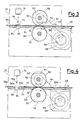
- the tearing device 10 comprises a framework 12, consisting of posts 14, 16 and 18, and cross bars or shoulders 20 and 22, connected to each other by an abutment plane 24 onto which a band 26, such as a paper band , is advanced with a sliding motion, the band having to be torn at predetermined weakening zpnes when the need arises of carrying out said tearing.
- Said band 26 is advanced along the direction of the arrow 28 owing to the motion of a first pair of perfectly cylindrical rollers 30 and 32, having equal diameters, and connected to each other by gears 34 and 36, the lower roller 32 engaging the lower surface of said band 26 through a window 38.
- the upper roller has coaxially mounted thereto a toothed wheel or like member 40 which, through a transmission member such as a chain or toothed belt, is driven from a toothed wheel 44 in turn driven by an electrical motor 46, of synchronous type, of step-by-step type or of reluctance type, by which the rollers 30 and 32 are driven at a given constant rotation speed, thus generating a more or less intense driving torque and a braking torque when said band 26 is drawn trying to cause the rollers 30 and 32 to overcome their normal rotation speed.
- a transmission member such as a chain or toothed belt
- Said band 26, by prosecuting its downstream sliding motion passes through a second pair of rollers 50 and 52, each having a planar bevel 54 and 56, provided for instance by milling, and connected to each other through gears 58 and 60, the gear 58 being coupled to a coaxial wheel 62 protruding there from and driven, through a transmission member 64, from a wheel 66 connected to a driving assembly 68 comprising an electric motor and a clutch, which can be of whatever type provided that it is capable of driving the rollers 50 and 52 at a peripheral speed definitely higher than that of the rollers 30 and 32.
- a window 70 provided in the abutment plane 24 above the roller 52 permits the circumferential periphery of the same roller to get into contact with the band 26 when said roller is driven together with the roller 50.
- a detector 74 such as an assembly comprising a light emitter and a photodetector, cause it to be activated owing to the modification of a light ray 76, or the like, whereby through a connection 78 a signal is sent to a pilot or drive unit 80 (of per se known type) in order to operate, through a connection 82, said motor-clutch assembly, whereby the motion of said electric motor is transmitted to said rollers 50 and 52.
- Another photodetector 84 is positioned below the abutment plane 24, at a window provided therewithin, for a function of band tearing detection to be more detailedly discussed hereinafter, this further photodetector sending its signals through a connection 86 to the same pilot unit 80.
- a further connection 88 from a shaft position detector to the pilot unit takes care of the detection of when the rollers 50 and 52 are returned with their planar bevels 54 and 56 facing to each other, then causing their stopping in such a position.
- the operation of the device of the present invention is made particularly evident from the figures 3 and 4, taken together with fig.1.
- a weakening zone 90 in the band 26 is formed at a certain distance upstream of the marked zone 72, said distance being readily assessed by a person skilled in this field from the dynamic features of the assembly carrying out the tearing operation, such as the moment of inertia of the rollers 50 and 52,the rotation speed of the motor of the motor and clutch assembly 68 and the like.
- the band 26, of white or essentially light paper does reflect and diffuse the light ray 76 emitted from the detector 74 which comprises a photodetector receiving back said reflected light ray 76.
- the detector 74 which comprises a photodetector receiving back said reflected light ray 76.
- said marked zone 72 consists of alternating dark and light segments substantially perpendicularly oriented with respect to the arrow 28 of the sliding direction of the band 26 whereby a modulated reflected signal is produced which can be readily recognized with respect to the absence of reflected light as resulting from the accidental introduction of a poorly reflecting item between the detector 74 and the band 26 or from the soiling of optical parts of the detector 74 itself.
- the reception of the signal through the connection 78 by the pilot unit 80 causes a clutch of the motor and clutch assembly 68 to be actuated, whereby said rollers 50 and 52 are driven into rotation and, as shown in fig.
Landscapes
- Life Sciences & Earth Sciences (AREA)
- Forests & Forestry (AREA)
- Engineering & Computer Science (AREA)
- Mechanical Engineering (AREA)
- Controlling Rewinding, Feeding, Winding, Or Abnormalities Of Webs (AREA)
- Perforating, Stamping-Out Or Severing By Means Other Than Cutting (AREA)
Applications Claiming Priority (2)
| Application Number | Priority Date | Filing Date | Title |
|---|---|---|---|
| IT2217788U | 1988-11-21 | ||
| IT8822177U IT215262Z2 (it) | 1988-11-21 | 1988-11-21 | Strapperina per nastri di materiali in fogli come nastri di carta. |
Publications (2)
| Publication Number | Publication Date |
|---|---|
| EP0370578A2 true EP0370578A2 (de) | 1990-05-30 |
| EP0370578A3 EP0370578A3 (de) | 1991-08-21 |
Family
ID=11192638
Family Applications (1)
| Application Number | Title | Priority Date | Filing Date |
|---|---|---|---|
| EP19890202942 Withdrawn EP0370578A3 (de) | 1988-11-21 | 1989-11-20 | Abreissvorrichtung für Bahnmaterial, beispielsweise Papierbahnen |
Country Status (3)
| Country | Link |
|---|---|
| US (1) | US4997119A (de) |
| EP (1) | EP0370578A3 (de) |
| IT (1) | IT215262Z2 (de) |
Cited By (6)
| Publication number | Priority date | Publication date | Assignee | Title |
|---|---|---|---|---|
| EP0479385A1 (de) * | 1990-10-03 | 1992-04-08 | Industria Grafica Meschi S.r.l. | Apparat zum Hochgeschwindigkeitsstapeln von Papierbögen oder eines kontinuierlichen Bandes mit Abreisstrennung entlang vorperforierter Linien |
| EP0506193A1 (de) * | 1991-03-27 | 1992-09-30 | Industria Grafica Meschi S.r.l. | Vorrichtung zum Abreissen eines Papierblattes oder dergleichen längs einer geraden, vorgestanzten, im wesentlichen in Querrichtung orientierten Linie |
| EP0516991A1 (de) * | 1991-06-05 | 1992-12-09 | WindmÀ¶ller & Hölscher | Vorrichtung zum Trennen von Abschnitten von einer mit Querperforationen versehenen Materialbahn |
| WO1993001118A1 (en) * | 1991-07-03 | 1993-01-21 | Lars Gunnarsson | A method and a device for separation of pieces from a perforated carboard track |
| EP0837020A2 (de) * | 1996-10-18 | 1998-04-22 | Fmc Corporation | Wickler zum Gebrauch mit einer Beutelherstellungsmaschine |
| EP3024739A4 (de) * | 2013-05-01 | 2017-09-13 | Northfield Corporation | Applikator für flexible schleifen und verfahren |
Families Citing this family (18)
| Publication number | Priority date | Publication date | Assignee | Title |
|---|---|---|---|---|
| EP0556071B1 (de) * | 1992-02-13 | 1997-09-17 | Fujitsu Limited | Fahrkartendrucker |
| US5540369A (en) * | 1993-12-07 | 1996-07-30 | Moore Business Forms, Inc. | Detaching linerless labels |
| DE19540148C1 (de) * | 1995-10-27 | 1997-04-24 | Windmoeller & Hoelscher | Vorrichtung zum Abtrennen von Zetteln von einer kontinuierlich geförderten Zettelbahn |
| US5853117A (en) * | 1995-10-31 | 1998-12-29 | Moore Business Forms, Inc. | Separator for linerless labels |
| US5961020A (en) * | 1996-03-11 | 1999-10-05 | Cmd Corporation | Separating a web at a line of weakness |
| US5979729A (en) * | 1996-03-11 | 1999-11-09 | Cmd Corporation | Separating a web at a line of weakness |
| CA2285920C (en) | 1997-04-03 | 2005-11-29 | Ebrahim Simhaee | Continuous roll of plastic bags |
| US6115993A (en) * | 1997-10-10 | 2000-09-12 | Bedford Industries, Inc. | Tag presenter |
| US20020144770A1 (en) | 2001-04-06 | 2002-10-10 | Stephane Mabit | Carrier-less patch protection including cassette and separation process |
| US7175127B2 (en) * | 2002-09-27 | 2007-02-13 | C.G. Bretting Manufacturing Company, Inc. | Rewinder apparatus and method |
| US7343723B2 (en) * | 2004-01-27 | 2008-03-18 | Free-Flow Packaging International, Inc. | Method and apparatus for pre-tearing strings of air-filled packing materials and the like |
| US20060059865A1 (en) * | 2004-09-22 | 2006-03-23 | Free-Flow Packaging International, Inc. | Method and apparatus for pre-tearing strings of air-filled packing materials |
| US7874509B2 (en) * | 2006-04-12 | 2011-01-25 | Kenney James W | Automated dispenser |
| US7836670B2 (en) * | 2006-10-18 | 2010-11-23 | Alain Cerf | Perforated film wrapping machine |
| US7540125B2 (en) * | 2007-03-26 | 2009-06-02 | Northfield Corporation | Bursting apparatus and method |
| US8342374B2 (en) * | 2009-02-11 | 2013-01-01 | Insight Promotions, Llc | Fragile premium separator |
| US8276797B2 (en) * | 2009-09-04 | 2012-10-02 | Insight Promotions, Llc | Premium separator with contoured spaced-apart belt |
| DE102014216192A1 (de) * | 2014-08-14 | 2016-02-18 | Krones Ag | Vorrichtung und Verfahren zum Aufbringen von Folienhülsen als Verschlusssicherung |
Citations (3)
| Publication number | Priority date | Publication date | Assignee | Title |
|---|---|---|---|---|
| US2400447A (en) * | 1940-04-25 | 1946-05-14 | American Mach & Foundry | Web-registering device |
| GB683411A (en) * | 1950-02-17 | 1952-11-26 | Jacob Otto Lundberg | Improvements in or relating to delivery apparatus for paper cutting machines |
| EP0094647A2 (de) * | 1982-05-14 | 1983-11-23 | Systemform Datenbelege GmbH | Vorrichtung zum Abtrennen von Endlosformularsätzen o. dgl. |
Family Cites Families (6)
| Publication number | Priority date | Publication date | Assignee | Title |
|---|---|---|---|---|
| US2717642A (en) * | 1952-11-20 | 1955-09-13 | Ibm | Machine for automatically bursting a continuous strip of stationery into sheets |
| US3741451A (en) * | 1971-01-04 | 1973-06-26 | Standard Register Co | Burster apparatus |
| US4025023A (en) * | 1975-10-31 | 1977-05-24 | International Business Machines Corporation | Burster apparatus |
| US4397410A (en) * | 1978-07-07 | 1983-08-09 | Swingline Inc. | Burster |
| DE2851894A1 (de) * | 1978-11-30 | 1980-06-12 | Agfa Gevaert Ag | Einrichtung zum trennen von vorperforierten baendern, vorzugsweise zusammenhaengenden taschen |
| US4375189A (en) * | 1981-04-30 | 1983-03-01 | Hobart Corporation | Label printer |
-
1988
- 1988-11-21 IT IT8822177U patent/IT215262Z2/it active
-
1989
- 1989-11-20 EP EP19890202942 patent/EP0370578A3/de not_active Withdrawn
- 1989-11-21 US US07/440,515 patent/US4997119A/en not_active Expired - Fee Related
Patent Citations (3)
| Publication number | Priority date | Publication date | Assignee | Title |
|---|---|---|---|---|
| US2400447A (en) * | 1940-04-25 | 1946-05-14 | American Mach & Foundry | Web-registering device |
| GB683411A (en) * | 1950-02-17 | 1952-11-26 | Jacob Otto Lundberg | Improvements in or relating to delivery apparatus for paper cutting machines |
| EP0094647A2 (de) * | 1982-05-14 | 1983-11-23 | Systemform Datenbelege GmbH | Vorrichtung zum Abtrennen von Endlosformularsätzen o. dgl. |
Cited By (9)
| Publication number | Priority date | Publication date | Assignee | Title |
|---|---|---|---|---|
| EP0479385A1 (de) * | 1990-10-03 | 1992-04-08 | Industria Grafica Meschi S.r.l. | Apparat zum Hochgeschwindigkeitsstapeln von Papierbögen oder eines kontinuierlichen Bandes mit Abreisstrennung entlang vorperforierter Linien |
| US5230453A (en) * | 1990-10-03 | 1993-07-27 | Industria Grafica Meschi Srl | Apparatus for high speed of stacking either sheets or forms as a continuous web or separated sheets with tear splitting along prepierced lines |
| EP0506193A1 (de) * | 1991-03-27 | 1992-09-30 | Industria Grafica Meschi S.r.l. | Vorrichtung zum Abreissen eines Papierblattes oder dergleichen längs einer geraden, vorgestanzten, im wesentlichen in Querrichtung orientierten Linie |
| EP0516991A1 (de) * | 1991-06-05 | 1992-12-09 | WindmÀ¶ller & Hölscher | Vorrichtung zum Trennen von Abschnitten von einer mit Querperforationen versehenen Materialbahn |
| WO1993001118A1 (en) * | 1991-07-03 | 1993-01-21 | Lars Gunnarsson | A method and a device for separation of pieces from a perforated carboard track |
| EP0837020A2 (de) * | 1996-10-18 | 1998-04-22 | Fmc Corporation | Wickler zum Gebrauch mit einer Beutelherstellungsmaschine |
| EP0837020A3 (de) * | 1996-10-18 | 1999-01-07 | Fmc Corporation | Wickler zum Gebrauch mit einer Beutelherstellungsmaschine |
| EP3024739A4 (de) * | 2013-05-01 | 2017-09-13 | Northfield Corporation | Applikator für flexible schleifen und verfahren |
| US10793309B2 (en) | 2013-05-01 | 2020-10-06 | Northfield Corporation | Flexible loop applicator and method |
Also Published As
| Publication number | Publication date |
|---|---|
| IT215262Z2 (it) | 1990-09-11 |
| IT8822177V0 (it) | 1988-11-21 |
| US4997119A (en) | 1991-03-05 |
| EP0370578A3 (de) | 1991-08-21 |
Similar Documents
| Publication | Publication Date | Title |
|---|---|---|
| US4997119A (en) | Tearing device for bands of sheet materials, such as paper bands | |
| US4284221A (en) | Apparatus for breaking weakened portions of running webs or the like | |
| US4415978A (en) | Cut-to-mark cut-off control automated for splice and order change | |
| US4243925A (en) | Register control system for web operating apparatus | |
| CA1295639C (en) | Method and an arrangement for the feeding of a material web | |
| GB2069200A (en) | Apparatus for counting documents | |
| GB1516075A (en) | Web registration detection by intermittent scanning | |
| JPH0684230B2 (ja) | 定尺位置決め装置 | |
| EP0072935B1 (de) | Vorrichtung zur fotoelektrischen Überwachung | |
| EP0359811B1 (de) | Doppelbogendetektor und separator | |
| US3819998A (en) | Dynamic braking control system | |
| US4570916A (en) | Document conveying method and apparatus | |
| US4542893A (en) | Overlapping document strip conveying method and apparatus | |
| GB1580300A (en) | Document jam detection apparatus | |
| US3992965A (en) | Method and arrangement for cutting and sorting photographic prints, and the like | |
| CA2212042A1 (en) | Jam monitoring device for a transport device for paper, especially for a paper tape | |
| EP0716036A1 (de) | Verfahren zum Abreissen von bedrucktem Endlospapier ohne Randlochung und entsprechende Abreiss- und Faltvorrichtung | |
| JPS606545A (ja) | 搬送物の検知装置 | |
| JP2563515B2 (ja) | 給紙装置 | |
| EP0182086B1 (de) | Verfahren und Apparat zum Bewegen von Endlosformularen | |
| JPS6125266B2 (de) | ||
| JPS58157656A (ja) | 単票の斜行插入検出機構 | |
| JPS5936063A (ja) | シ−ト状物の巻取張力制御方法 | |
| KR900008021Y1 (ko) | 엘리베이터의 이동거리 검출장치 | |
| KR940011208A (ko) | 인쇄 용지의 사행 방지장치 |
Legal Events
| Date | Code | Title | Description |
|---|---|---|---|
| PUAI | Public reference made under article 153(3) epc to a published international application that has entered the european phase |
Free format text: ORIGINAL CODE: 0009012 |
|
| AK | Designated contracting states |
Kind code of ref document: A2 Designated state(s): AT BE CH DE ES FR GB GR IT LI LU NL SE |
|
| PUAL | Search report despatched |
Free format text: ORIGINAL CODE: 0009013 |
|
| AK | Designated contracting states |
Kind code of ref document: A3 Designated state(s): AT BE CH DE ES FR GB GR IT LI LU NL SE |
|
| STAA | Information on the status of an ep patent application or granted ep patent |
Free format text: STATUS: THE APPLICATION IS DEEMED TO BE WITHDRAWN |
|
| 18D | Application deemed to be withdrawn |
Effective date: 19920222 |