EP0369855B1 - Automatic unit for distributing and fitting rings, especially composite rings, on engine pistons - Google Patents
Automatic unit for distributing and fitting rings, especially composite rings, on engine pistons Download PDFInfo
- Publication number
- EP0369855B1 EP0369855B1 EP89403054A EP89403054A EP0369855B1 EP 0369855 B1 EP0369855 B1 EP 0369855B1 EP 89403054 A EP89403054 A EP 89403054A EP 89403054 A EP89403054 A EP 89403054A EP 0369855 B1 EP0369855 B1 EP 0369855B1
- Authority
- EP
- European Patent Office
- Prior art keywords
- rings
- pistons
- unit according
- piston
- ring
- Prior art date
- Legal status (The legal status is an assumption and is not a legal conclusion. Google has not performed a legal analysis and makes no representation as to the accuracy of the status listed.)
- Expired - Lifetime
Links
Images


Classifications
-
- B—PERFORMING OPERATIONS; TRANSPORTING
- B23—MACHINE TOOLS; METAL-WORKING NOT OTHERWISE PROVIDED FOR
- B23P—METAL-WORKING NOT OTHERWISE PROVIDED FOR; COMBINED OPERATIONS; UNIVERSAL MACHINE TOOLS
- B23P19/00—Machines for simply fitting together or separating metal parts or objects, or metal and non-metal parts, whether or not involving some deformation; Tools or devices therefor so far as not provided for in other classes
- B23P19/04—Machines for simply fitting together or separating metal parts or objects, or metal and non-metal parts, whether or not involving some deformation; Tools or devices therefor so far as not provided for in other classes for assembling or disassembling parts
- B23P19/08—Machines for placing washers, circlips, or the like on bolts or other members
- B23P19/084—Machines for placing washers, circlips, or the like on bolts or other members for placing resilient or flexible rings, e.g. O-rings, circlips
- B23P19/088—Piston rings in piston grooves
-
- B—PERFORMING OPERATIONS; TRANSPORTING
- B23—MACHINE TOOLS; METAL-WORKING NOT OTHERWISE PROVIDED FOR
- B23P—METAL-WORKING NOT OTHERWISE PROVIDED FOR; COMBINED OPERATIONS; UNIVERSAL MACHINE TOOLS
- B23P19/00—Machines for simply fitting together or separating metal parts or objects, or metal and non-metal parts, whether or not involving some deformation; Tools or devices therefor so far as not provided for in other classes
- B23P19/001—Article feeders for assembling machines
- B23P19/003—Escapement mechanisms used therewith
-
- Y—GENERAL TAGGING OF NEW TECHNOLOGICAL DEVELOPMENTS; GENERAL TAGGING OF CROSS-SECTIONAL TECHNOLOGIES SPANNING OVER SEVERAL SECTIONS OF THE IPC; TECHNICAL SUBJECTS COVERED BY FORMER USPC CROSS-REFERENCE ART COLLECTIONS [XRACs] AND DIGESTS
- Y10—TECHNICAL SUBJECTS COVERED BY FORMER USPC
- Y10T—TECHNICAL SUBJECTS COVERED BY FORMER US CLASSIFICATION
- Y10T24/00—Buckles, buttons, clasps, etc.
- Y10T24/37—Drawstring, laced-fastener, or separate essential cooperating device therefor
- Y10T24/375—Drawstring, laced-fastener, or separate essential cooperating device therefor having hook shaped directing means
- Y10T24/3753—Drawstring, laced-fastener, or separate essential cooperating device therefor having hook shaped directing means and movable component or surface for closing throat
-
- Y—GENERAL TAGGING OF NEW TECHNOLOGICAL DEVELOPMENTS; GENERAL TAGGING OF CROSS-SECTIONAL TECHNOLOGIES SPANNING OVER SEVERAL SECTIONS OF THE IPC; TECHNICAL SUBJECTS COVERED BY FORMER USPC CROSS-REFERENCE ART COLLECTIONS [XRACs] AND DIGESTS
- Y10—TECHNICAL SUBJECTS COVERED BY FORMER USPC
- Y10T—TECHNICAL SUBJECTS COVERED BY FORMER US CLASSIFICATION
- Y10T29/00—Metal working
- Y10T29/53—Means to assemble or disassemble
- Y10T29/536—Piston ring inserter or remover
Definitions
- the present invention relates to an automatic unit for distributing and fitting segments, particularly composite ones, on pistons of internal combustion engines presented by a robot on this unit of the type integrated in a robotic assembly line, and provided with automatic means for gripping the pistons, detecting the type of pistons removed, initializing and referencing the piston grooves in height on the segment stacking warheads, selection and presentation of the warheads.
- the invention therefore aims to remedy these drawbacks, in the simplest way.
- the object of the present invention is therefore an automatic unit as defined in claim 1.
- This arrangement allows an effective separation of these expanders for the installation of composite segments on the pistons.
- this unit comprises a device for automatically placing open segments expanded when passing over a corresponding warhead, which essentially consists of a plurality of fingers of elastomeric material and with an inverted corolla configuration.
- This device makes it very easy to take the segments through the feed drawer and ensure their expansion over the length of the receiving warhead.
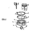
- FIG. 1 shows a scraper composite segment 1 which comprises an intermediate elastic part 1a, called an expander, held between two thin flat rings 1b and 1c, as well as a sealing segment 2 and a gun segment 3.
- an intermediate elastic part 1a called an expander
- the segments arrive previously stacked in magazines 4 oriented along the slots.
- FIGS. 2 to 8 They are separated by means of a specific separation device 6 illustrated in FIGS. 2 to 8 in the case of expanders 1a commonly designated “U-flex segments", or by means of a drawer 8 in the case of the rings thin 1b and 1c.
- An annex device 12 provided with a jack carries a set of six fingers 14 made of elastomeric material such as polyurethane.
- the arrangement of these fingers in inverted corolla makes it possible, on the one hand, to take the segment through the drawer 8 and, on the other hand, to ensure, thanks to the elasticity of this material, the expansion over all the length of the warhead 10 ( Figure 2).
- a piston 16 to be fitted with segments is gripped by a clamp 18 with four fingers 20 moving in pairs two by two. Then, it is deposited on a reference surface where it is re-entered by this clamp at a known level ( Figure 2).
- This operation aims to place the grooves 22 to receive the segments at a known dimension.
- the piston 16 is then transferred above the warhead 10 in which it descends to the level of fitting of the corresponding segment.
- the device 12 for automatic positioning of segments ensures that the segment will come into abutment against a reconformation ceiling 24, and guarantees the release of this segment at the end of the warhead.
- the piston 16 is then released from the warhead, with the segment mounted ( Figure 2).
- the expander separation device 1a comprises two pairs of helical ramps with opposite winding directions (two on the right 26, 27 and two on the left 28, 29) which are driven simultaneously by a ring gear 30.
- Two propellers are opposite in direction to the other two to balance the friction forces produced between said ramps and the expander whose rotation is not desired.
- the exit from the helical ramps corresponds to the end of the magazine 4 (held by the interior of the expander).
- the expander 1a then comes to be housed in a cavity 36 formed in the automatic feeding drawer 8 (FIG. 2).
- a finger 38 maintains the latter during transport under the warhead 10 where it is retracted by a knife 40. It is returned to its initial position by two springs 42 ( Figures 6, 7 and 8).
Landscapes
- Engineering & Computer Science (AREA)
- Mechanical Engineering (AREA)
- Automatic Assembly (AREA)
- Valve Device For Special Equipments (AREA)
- Pistons, Piston Rings, And Cylinders (AREA)
- Medicinal Preparation (AREA)
- Medicines That Contain Protein Lipid Enzymes And Other Medicines (AREA)
- Pharmaceuticals Containing Other Organic And Inorganic Compounds (AREA)
- Fuel-Injection Apparatus (AREA)
Abstract
Description
La présente invention se rapporte à une unité automatique de distribution et de pose de segments notamment composites sur des pistons de moteurs à combustion interne présentés par un robot sur cette unité du type intégrée dans une ligne d'assemblage robotisée, et pourvue de moyens automatiques de préhension des pistons, de détection du type de pistons prélevés, d'initialisation et de référencement en hauteur des gorges des pistons sur les ogives d'empilement de segments, de sélection et de présentation des ogives.The present invention relates to an automatic unit for distributing and fitting segments, particularly composite ones, on pistons of internal combustion engines presented by a robot on this unit of the type integrated in a robotic assembly line, and provided with automatic means for gripping the pistons, detecting the type of pistons removed, initializing and referencing the piston grooves in height on the segment stacking warheads, selection and presentation of the warheads.
La demanderesse a déjà étudié et réalisé des machines automatiques semblables qui utilisent des ogives sur lesquelles sont empilés des segments d'étanchéités simples, voir par exemple le document EP-A-0341161, qui est compris dans l'état de la technique comme défini à l'Art. 54 (3) CBE.The applicant has already studied and produced similar automatic machines which use warheads on which are stacked segments of simple seals, see for example the document EP-A-0341161, which is included in the state of the art as defined in art. 54 (3) EPC.
Bien que ces machines puissent tenir compte des variantes de moteurs, de pistons et de segments, elles ne conviennent pas à la distribution et à la pose de segments composites tels qu'un segment racleur constitué de deux anneaux plats et minces, séparés par un expandeur élastique.Although these machines can take into account the variants of engines, pistons and segments, they are not suitable for the distribution and installation of composite segments such as a scraper segment made up of two flat and thin rings, separated by an expander elastic.
En effet, les expandeurs présentés sous forme de pile ont tendance à s'emboîter les uns dans les autres ce qui interdit de les distribuer avec un système classique à tiroir tel que décrit dans le document JP-A-58.206.331.In fact, the expanders presented in the form of a stack tend to nest into each other, which prohibits distributing them with a conventional drawer system as described in document JP-A-58,206,331.
Le document US-A-1.634.566 décrit un dispositif distributeur de pièces cylindriques emboîtées grâce à l'utilisation de rampes hélicoïdales. Ces rampes agissant sur les bords latéraux des pièces entraînent ces dernières une à une.The document US-A-1,634,566 describes a device for dispensing nested cylindrical parts through the use of helical ramps. These ramps acting on the lateral edges of the pieces drive the latter one by one.
Malheureusement ce dispositif entraîne la rotation de la pièce ce qui est incompatible avec la distribution de segment fragile en torsion et dont la position angulaire doit être indexée précisément pour assurer leur montage.Unfortunately, this device causes the part to rotate, which is incompatible with the distribution of fragile torsional segments and whose angular position must be precisely indexed to ensure their mounting.
L'invention a donc pour but de remédier à ces inconvénients, de la manière la plus simple.The invention therefore aims to remedy these drawbacks, in the simplest way.
L'objet de la présente invention est donc une unité automatique telle que définie à la revendication 1.The object of the present invention is therefore an automatic unit as defined in
Cette disposition permet une séparation efficace de ces expandeurs pour la pose de segments composites sur les pistons.This arrangement allows an effective separation of these expanders for the installation of composite segments on the pistons.
Suivant une autre particularité, cette unité comporte un dispositif de mise en place automatique de segments ouverts expansés au passage sur une ogive correspondante, qui est constitué essentiellement par une pluralité de doigts en matériau élastomère et à configuration de corolle inversée.According to another particularity, this unit comprises a device for automatically placing open segments expanded when passing over a corresponding warhead, which essentially consists of a plurality of fingers of elastomeric material and with an inverted corolla configuration.
Ce dispositif permet très simplement de prélever les segments au travers du tiroir d'amenage et d'en assurer l'expansion sur la longueur de l'ogive réceptrice.This device makes it very easy to take the segments through the feed drawer and ensure their expansion over the length of the receiving warhead.
D'autres particularités et avantages de l'invention ressortiront plus clairement à la lecture de la description qui suit d'un mode de réalisation préféré, donné à titre d'exemple non limitatif, en référence aux dessins annexés dans lesquels :
- la figure 1 représente un exemple de montage d'un segment racleur composite et de deux segments d'étanchéité conventionnels sur un piston,
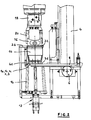
- la figure 2 représente une vue de face de l'unité conforme à l'invention,
- la figure 3 représente une vue de dessus de cette unité,
- les figures 4 et 5 représentent des vues de détail en coupe axiale du dispositif de séparation d'expandeurs élastiques,
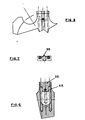
- les figures 6, 7 et 8 représentent des vues de détail montrant un doigt accessoire au dispositif de séparation illustré sur les figures 4 et 5,
- la figure 9 représente une vue partielle de côté de l'unité illustrée à la figure 2.
- FIG. 1 represents an example of mounting a composite scraper segment and two conventional sealing segments on a piston,
- FIG. 2 represents a front view of the unit according to the invention,
- FIG. 3 represents a top view of this unit,
- FIGS. 4 and 5 show detailed views in axial section of the device for separating elastic expanders,
- Figures 6, 7 and 8 show detailed views showing a finger accessory to the separation device illustrated in FIGS. 4 and 5,
- FIG. 9 represents a partial side view of the unit illustrated in FIG. 2.
La figure 1 montre un segment composite racleur 1 qui comporte une partie élastique intermédiaire 1a, appelée expandeur, tenue entre deux anneaux plats minces 1b et 1c, ainsi qu'un segment d'étanchéité 2 et un segment coup de feu 3.FIG. 1 shows a
L'unité automatique de distribution et de pose de segments illustrée à la figure 2 est intégrée dans une ligne d'assemblage comportant plusieurs sites robotisés suivant les cadences recherchées, chaque site, comprenant :
- une machine de distribution unitaire de segments capable de détromper les différents types de segments, d'approvisionner en continu le site, et d'assurer le changement de type de segment,
- un robot ayant pour fonctions de saisir un à un les pistons, de les déposer sur un poste d'initialisation, et de les reprendre pour les présenter successivement dans l'alésage des ogives de mise en place des segments en fournissant une position en hauteur précise de la gorge dans laquelle est déposé le segment correspondant, à partir de chacune de ces ogives.
- a unitary segment distribution machine capable of disrupting the different types of segments, of continuously supplying the site, and of ensuring the change of type of segment,
- a robot whose function is to seize the pistons one by one, deposit them on an initialization station, and take them up again to present them successively in the bore of the segment placement warheads by providing a precise height position of the groove in which the corresponding segment is deposited, from each of these warheads.
Les segments arrivent préalablement empilés dans des magasins 4 orientés suivant les fentes.The segments arrive previously stacked in
Ils sont séparés au moyen d'un dispositif spécifique de séparation 6 illustré sur les figures 2 à 8 dans le cas des expandeurs la couramment désignés "segments U-flex", ou par l'intermédiaire d'un tiroir 8 dans le cas des anneaux minces 1b et 1c.They are separated by means of a
Ces segments sont amenés par ce tiroir automatique 8 sous une ogive d'expansion 10 (figures 2 et 9).These segments are brought by this
Un dispositif annexe 12 pourvu d'un vérin porte un ensemble de six doigts 14 en matériau élastomère tel que le polyuréthane. La disposition de ces doigts en corolle inversée permet, d'une part, de prélever le segment au travers du tiroir 8 et, d'autre part, d'en assurer, grâce à l'élasticité de ce matériau, l'expansion sur toute la longueur de l'ogive 10 (figure 2).An
Un piston 16 à équiper de segments est saisi par une pince 18 à quatre doigts 20 se déplaçant parallèlement deux à deux. Puis, il est déposé sur une surface de référence où il est ressaisi par cette pince à un niveau connu (figure 2).A
Cette opération a pour but de placer les gorges 22 devant recevoir les segments à une cote connue.This operation aims to place the
Le piston 16 est alors transféré au-dessus de l'ogive 10 dans laquelle il descend jusqu'au niveau de pose du segment correspondant.The
En fin d'expansion, le dispositif 12 de mise en place automatique de segments vient assurer une mise en butée du segment contre un plafond de reconformage 24, et garantit le lâcher de ce segment en extrémité d'ogive. Le piston 16 est alors dégagé de l'ogive, avec le segment monté (figure 2).At the end of expansion, the
Comme le montrent les figures 3, 4 et 5, le dispositif de séparation des expandeurs 1a comprend deux paires de rampes hélicoïdales à sens d'enroulement contraires (deux à droite 26, 27 et deux à gauche 28, 29) qui sont entraînées simultanément par une couronne dentée 30.As shown in FIGS. 3, 4 and 5, the
Il incorpore aussi un mécanisme à échappement 32 commandé par un vérin 34 qui fait effectuer à cette couronne dentée la portion de tour correspondant à un tour de rampe hélicoïdale.It also incorporates an
Durant cette manoeuvre, l'expandeur 1a a été pris dans la rampe et a donc avancé d'un pas d'hélice.During this maneuver, the
Deux hélices sont opposées en sens aux deux autres pour équilibrer les efforts de frottement produits entre lesdites rampes et l'expandeur dont la rotation n'est pas souhaitée.Two propellers are opposite in direction to the other two to balance the friction forces produced between said ramps and the expander whose rotation is not desired.
La sortie des rampes hélicoïdales correspond à l'extrémité du magasin 4 (maintien par l'intérieur de l'expandeur). L'expandeur 1a vient ensuite se loger dans une empreinte 36 ménagée dans le tiroir d'amenage automatique 8 (figure 2).The exit from the helical ramps corresponds to the end of the magazine 4 (held by the interior of the expander). The
Pour assurer la continuité de l'orientation de l'expandeur, un doigt 38 maintient celui-ci au cours du transport sous l'ogive 10 où il est escamoté par un couteau 40. Il est rappelé dans sa position initiale par deux ressorts 42 (figures 6, 7 et 8).To ensure the continuity of the orientation of the expander, a
Le cycle de fonctionnement se poursuit alors comme expliqué précédemment.The operating cycle then continues as previously explained.
Claims (6)
Priority Applications (1)
| Application Number | Priority Date | Filing Date | Title |
|---|---|---|---|
| AT89403054T ATE79581T1 (en) | 1988-11-18 | 1989-11-07 | AUTOMATIC UNIT FOR DISTRIBUTING AND PLACING RINGS, ESPECIALLY COMPOSITE RINGS, ON ENGINE PISTONS. |
Applications Claiming Priority (2)
| Application Number | Priority Date | Filing Date | Title |
|---|---|---|---|
| FR8815031 | 1988-11-18 | ||
| FR8815031A FR2639271B1 (en) | 1988-11-18 | 1988-11-18 | DISTRIBUTION AND LAYING UNIT OF PARTICULARLY SEGMENTS ON ENGINE PISTONS |
Publications (2)
| Publication Number | Publication Date |
|---|---|
| EP0369855A1 EP0369855A1 (en) | 1990-05-23 |
| EP0369855B1 true EP0369855B1 (en) | 1992-08-19 |
Family
ID=9371980
Family Applications (1)
| Application Number | Title | Priority Date | Filing Date |
|---|---|---|---|
| EP89403054A Expired - Lifetime EP0369855B1 (en) | 1988-11-18 | 1989-11-07 | Automatic unit for distributing and fitting rings, especially composite rings, on engine pistons |
Country Status (7)
| Country | Link |
|---|---|
| US (1) | US4967459A (en) |
| EP (1) | EP0369855B1 (en) |
| AT (1) | ATE79581T1 (en) |
| CA (1) | CA2003310A1 (en) |
| DE (1) | DE68902537T2 (en) |
| ES (1) | ES2034712T3 (en) |
| FR (1) | FR2639271B1 (en) |
Families Citing this family (9)
| Publication number | Priority date | Publication date | Assignee | Title |
|---|---|---|---|---|
| FR2679812B1 (en) * | 1991-07-31 | 1995-11-10 | Floquet Monopole | MACHINE FOR THE AUTOMATIC LAYING OF SEGMENTS ON PISTONS. |
| US5303465A (en) * | 1992-04-27 | 1994-04-19 | Honda Giken Kogyo Kabushiki Kaisha | Method of assembling piston ring and method of assembling set oil ring and apparatus for assembling set oil ring |
| US5404629A (en) * | 1993-10-15 | 1995-04-11 | Micro-Precision Operations, Inc. | Piston ring apparatus |
| US5435056A (en) * | 1993-10-15 | 1995-07-25 | Micro-Precision Operations, Inc. | Piston ring apparatus |
| JPH07178629A (en) * | 1993-12-22 | 1995-07-18 | Honda Motor Co Ltd | Method of assembling oil ring set onto piston |
| US5601540A (en) * | 1995-07-14 | 1997-02-11 | Stevens; Brian | Apparatus for positioning a split ring over an enlarged flange |
| FR2763876B1 (en) * | 1997-05-27 | 1999-08-27 | Renault Automation | DEVICE FOR DEPLOYING SPREADING ELEMENTS THAT ARE IN THE CONSTITUTION OF AN OIL SCRAPER SEGMENT |
| WO2005056999A1 (en) * | 2003-12-12 | 2005-06-23 | Hirata Corporation | Installation device and installation method for piston ring |
| TWI597443B (en) * | 2015-07-27 | 2017-09-01 | 泰茂實業股份有限公司 | Auxiliary device for installing piston rings |
Citations (1)
| Publication number | Priority date | Publication date | Assignee | Title |
|---|---|---|---|---|
| EP0341161A1 (en) * | 1988-05-05 | 1989-11-08 | Renault Automation | Automatic machine for distributing and fitting rings on combustion engines |
Family Cites Families (15)
| Publication number | Priority date | Publication date | Assignee | Title |
|---|---|---|---|---|
| US1525528A (en) * | 1920-09-10 | 1925-02-10 | American Can Co | Curling, counting, and stacking device |
| US1634566A (en) * | 1923-04-03 | 1927-07-05 | Individual Drinking Cup Co | Cup dispenser |
| US2792625A (en) * | 1956-03-21 | 1957-05-21 | Gen Motors Corp | Ring assembly machine |
| US3018593A (en) * | 1960-02-12 | 1962-01-30 | Aluminum Co Of America | Release and transfer device |
| US3793695A (en) * | 1972-08-29 | 1974-02-26 | Sealed Power Corp | Device for automatically loading an oil ring spacer-expander into the oil ring groove of a piston |
| US3889342A (en) * | 1973-09-12 | 1975-06-17 | Ramsey Corp | Apparatus for assembling piston ring end guides |
| US3977566A (en) * | 1975-10-31 | 1976-08-31 | Bell Telephone Laboratories, Incorporated | Semiconductor wafer handling apparatus |
| US4047276A (en) * | 1975-11-28 | 1977-09-13 | Designeers Midwest | Apparatus for dispensing rings and for applying piston rings to pistons |
| DE2840863C2 (en) * | 1978-09-20 | 1982-08-26 | Goetze Ag, 5093 Burscheid | Device for positioning non-round piston rings |
| JPS6139695Y2 (en) * | 1980-05-19 | 1986-11-13 | ||
| JPS5741147A (en) * | 1980-08-12 | 1982-03-08 | Nippon Piston Ring Co Ltd | Constant number piston ring separating device |
| US4379234A (en) * | 1981-05-15 | 1983-04-05 | Cummins Engine Company, Inc. | Electro optic controlled piston ring installing apparatus |
| JPS58181525A (en) * | 1982-04-14 | 1983-10-24 | Nippon Piston Ring Co Ltd | Automatic inserter for piston ring |
| JPS58206331A (en) * | 1982-05-28 | 1983-12-01 | Nippon Piston Ring Co Ltd | Automatic piston ring inserting apparatus |
| JPH0780096B2 (en) * | 1987-01-16 | 1995-08-30 | 本田技研工業株式会社 | Automatic piston ring assembly device for pistons |
-
1988
- 1988-11-18 FR FR8815031A patent/FR2639271B1/en not_active Expired - Lifetime
-
1989
- 1989-11-07 DE DE8989403054T patent/DE68902537T2/en not_active Expired - Fee Related
- 1989-11-07 AT AT89403054T patent/ATE79581T1/en active
- 1989-11-07 EP EP89403054A patent/EP0369855B1/en not_active Expired - Lifetime
- 1989-11-07 ES ES198989403054T patent/ES2034712T3/en not_active Expired - Lifetime
- 1989-11-17 CA CA002003310A patent/CA2003310A1/en not_active Abandoned
- 1989-11-17 US US07/437,616 patent/US4967459A/en not_active Expired - Fee Related
Patent Citations (1)
| Publication number | Priority date | Publication date | Assignee | Title |
|---|---|---|---|---|
| EP0341161A1 (en) * | 1988-05-05 | 1989-11-08 | Renault Automation | Automatic machine for distributing and fitting rings on combustion engines |
Also Published As
| Publication number | Publication date |
|---|---|
| DE68902537T2 (en) | 1993-03-25 |
| EP0369855A1 (en) | 1990-05-23 |
| FR2639271B1 (en) | 1990-12-28 |
| FR2639271A1 (en) | 1990-05-25 |
| ATE79581T1 (en) | 1992-09-15 |
| DE68902537D1 (en) | 1992-09-24 |
| ES2034712T3 (en) | 1993-04-01 |
| CA2003310A1 (en) | 1990-05-18 |
| US4967459A (en) | 1990-11-06 |
Similar Documents
| Publication | Publication Date | Title |
|---|---|---|
| EP0369855B1 (en) | Automatic unit for distributing and fitting rings, especially composite rings, on engine pistons | |
| EP1092939B1 (en) | Device for connecting a cartridge case base to a cartridge case and cartridge case base suitable for such a connecting device | |
| FR2587246A1 (en) | AUTOMATIC APPARATUS FOR INSTALLING FIXING COMPONENTS SUCH AS RIVETS | |
| EP0723086B1 (en) | Screw with a separable head and screwing tool for such a screw | |
| FR2664883A1 (en) | ROTARY MARGIN FOR THE PRECISE PLACEMENT OF SHEET ELEMENTS ON FLAT SUPPORTS. | |
| CH607979A5 (en) | Device for handling stackable articles | |
| EP0067731B1 (en) | Device for affixing a container to an airplane, especially a flare dispenser | |
| FR2946423A1 (en) | DEVICE FOR OPENING AND LOCKING A MUNITION STACK | |
| EP1475601B1 (en) | Subcalibre projectile, rod and sabot constituting such a projectile | |
| EP0539257B1 (en) | Cargo munition | |
| EP0401115B1 (en) | Holding device for a projectile in relation to a telescoped ammunition case | |
| EP2253926B1 (en) | Separating device for propellant charge modules | |
| EP3430347B1 (en) | Target launching machine | |
| EP0200584B1 (en) | Externally powered automatic gun | |
| FR2668204A1 (en) | ENGINE STARTER MECHANISM. | |
| EP0580914A1 (en) | Clay pigeon launching apparatus for sport shooting | |
| EP3194310B1 (en) | Device for separating small loose objects | |
| EP0457627B1 (en) | Device for feeding rings to an automatic machine for fitting rings on internal combustion motor pistons | |
| EP0000451B1 (en) | Article-retention clamp, a system for hanging, removing and overlapping application of such a clamp, and a handling device to put this clamp and system into use | |
| FR2627411A1 (en) | DEVICE AND METHOD FOR THE AUTOMATIC PLACEMENT OF CLAMP COLLARS | |
| EP3715775B1 (en) | Portable machine for connecting links and ammunition | |
| EP3234494B1 (en) | Target-throwing machine, and the adjustment method thereof | |
| EP0531594B1 (en) | Device for feeding ammunition to an automatic weapon | |
| EP3502014A1 (en) | System for controlled distribution of components | |
| EP0628478B1 (en) | Device for ejecting removable object attached to a structure |
Legal Events
| Date | Code | Title | Description |
|---|---|---|---|
| PUAI | Public reference made under article 153(3) epc to a published international application that has entered the european phase |
Free format text: ORIGINAL CODE: 0009012 |
|
| 17P | Request for examination filed |
Effective date: 19891110 |
|
| AK | Designated contracting states |
Kind code of ref document: A1 Designated state(s): AT BE CH DE ES GB GR IT LI NL SE |
|
| 17Q | First examination report despatched |
Effective date: 19910426 |
|
| GRAA | (expected) grant |
Free format text: ORIGINAL CODE: 0009210 |
|
| AK | Designated contracting states |
Kind code of ref document: B1 Designated state(s): AT BE CH DE ES GB GR IT LI NL SE |
|
| PG25 | Lapsed in a contracting state [announced via postgrant information from national office to epo] |
Ref country code: NL Effective date: 19920819 Ref country code: GR Free format text: LAPSE BECAUSE OF FAILURE TO SUBMIT A TRANSLATION OF THE DESCRIPTION OR TO PAY THE FEE WITHIN THE PRESCRIBED TIME-LIMIT Effective date: 19920819 Ref country code: AT Effective date: 19920819 |
|
| REF | Corresponds to: |
Ref document number: 79581 Country of ref document: AT Date of ref document: 19920915 Kind code of ref document: T |
|
| ITF | It: translation for a ep patent filed |
Owner name: JACOBACCI & PERANI S.P.A. |
|
| GBT | Gb: translation of ep patent filed (gb section 77(6)(a)/1977) | ||
| REF | Corresponds to: |
Ref document number: 68902537 Country of ref document: DE Date of ref document: 19920924 |
|
| PG25 | Lapsed in a contracting state [announced via postgrant information from national office to epo] |
Ref country code: LI Effective date: 19921130 Ref country code: CH Effective date: 19921130 |
|
| NLV1 | Nl: lapsed or annulled due to failure to fulfill the requirements of art. 29p and 29m of the patents act | ||
| REG | Reference to a national code |
Ref country code: ES Ref legal event code: FG2A Ref document number: 2034712 Country of ref document: ES Kind code of ref document: T3 |
|
| PLBE | No opposition filed within time limit |
Free format text: ORIGINAL CODE: 0009261 |
|
| STAA | Information on the status of an ep patent application or granted ep patent |
Free format text: STATUS: NO OPPOSITION FILED WITHIN TIME LIMIT |
|
| REG | Reference to a national code |
Ref country code: CH Ref legal event code: PL |
|
| 26N | No opposition filed | ||
| EAL | Se: european patent in force in sweden |
Ref document number: 89403054.3 |
|
| PGFP | Annual fee paid to national office [announced via postgrant information from national office to epo] |
Ref country code: GB Payment date: 19971013 Year of fee payment: 9 |
|
| PGFP | Annual fee paid to national office [announced via postgrant information from national office to epo] |
Ref country code: SE Payment date: 19971024 Year of fee payment: 9 |
|
| PGFP | Annual fee paid to national office [announced via postgrant information from national office to epo] |
Ref country code: BE Payment date: 19971030 Year of fee payment: 9 |
|
| PGFP | Annual fee paid to national office [announced via postgrant information from national office to epo] |
Ref country code: DE Payment date: 19971115 Year of fee payment: 9 |
|
| PGFP | Annual fee paid to national office [announced via postgrant information from national office to epo] |
Ref country code: ES Payment date: 19971117 Year of fee payment: 9 |
|
| PG25 | Lapsed in a contracting state [announced via postgrant information from national office to epo] |
Ref country code: GB Free format text: LAPSE BECAUSE OF NON-PAYMENT OF DUE FEES Effective date: 19981107 |
|
| PG25 | Lapsed in a contracting state [announced via postgrant information from national office to epo] |
Ref country code: SE Free format text: LAPSE BECAUSE OF NON-PAYMENT OF DUE FEES Effective date: 19981108 |
|
| PG25 | Lapsed in a contracting state [announced via postgrant information from national office to epo] |
Ref country code: ES Free format text: LAPSE BECAUSE OF EXPIRATION OF PROTECTION Effective date: 19981110 |
|
| PG25 | Lapsed in a contracting state [announced via postgrant information from national office to epo] |
Ref country code: BE Free format text: LAPSE BECAUSE OF NON-PAYMENT OF DUE FEES Effective date: 19981130 |
|
| BERE | Be: lapsed |
Owner name: RENAULT AUTOMATION Effective date: 19981130 |
|
| GBPC | Gb: european patent ceased through non-payment of renewal fee |
Effective date: 19981107 |
|
| EUG | Se: european patent has lapsed |
Ref document number: 89403054.3 |
|
| PG25 | Lapsed in a contracting state [announced via postgrant information from national office to epo] |
Ref country code: DE Free format text: LAPSE BECAUSE OF NON-PAYMENT OF DUE FEES Effective date: 19990901 |
|
| REG | Reference to a national code |
Ref country code: ES Ref legal event code: FD2A Effective date: 20010301 |
|
| PG25 | Lapsed in a contracting state [announced via postgrant information from national office to epo] |
Ref country code: IT Free format text: LAPSE BECAUSE OF NON-PAYMENT OF DUE FEES;WARNING: LAPSES OF ITALIAN PATENTS WITH EFFECTIVE DATE BEFORE 2007 MAY HAVE OCCURRED AT ANY TIME BEFORE 2007. THE CORRECT EFFECTIVE DATE MAY BE DIFFERENT FROM THE ONE RECORDED. Effective date: 20051107 |