EP0368386B1 - Lenkrad für Kraftfahrzeuge mit Befestigungsplatten zwischen Speichen und Felge - Google Patents
Lenkrad für Kraftfahrzeuge mit Befestigungsplatten zwischen Speichen und Felge Download PDFInfo
- Publication number
- EP0368386B1 EP0368386B1 EP89202721A EP89202721A EP0368386B1 EP 0368386 B1 EP0368386 B1 EP 0368386B1 EP 89202721 A EP89202721 A EP 89202721A EP 89202721 A EP89202721 A EP 89202721A EP 0368386 B1 EP0368386 B1 EP 0368386B1
- Authority
- EP
- European Patent Office
- Prior art keywords
- steering wheel
- plate
- spokes
- motor vehicles
- rim
- Prior art date
- Legal status (The legal status is an assumption and is not a legal conclusion. Google has not performed a legal analysis and makes no representation as to the accuracy of the status listed.)
- Expired - Lifetime
Links
- 230000000295 complement effect Effects 0.000 claims description 2
- 239000007769 metal material Substances 0.000 claims description 2
- 238000004140 cleaning Methods 0.000 description 3
- 239000000428 dust Substances 0.000 description 3
- 238000004519 manufacturing process Methods 0.000 description 2
- 230000003749 cleanliness Effects 0.000 description 1
- 239000011248 coating agent Substances 0.000 description 1
- 238000000576 coating method Methods 0.000 description 1
- 230000007547 defect Effects 0.000 description 1
- 239000010985 leather Substances 0.000 description 1
- 239000003973 paint Substances 0.000 description 1
- 230000000737 periodic effect Effects 0.000 description 1
- 235000019640 taste Nutrition 0.000 description 1
Images
Classifications
-
- B—PERFORMING OPERATIONS; TRANSPORTING
- B62—LAND VEHICLES FOR TRAVELLING OTHERWISE THAN ON RAILS
- B62D—MOTOR VEHICLES; TRAILERS
- B62D1/00—Steering controls, i.e. means for initiating a change of direction of the vehicle
- B62D1/02—Steering controls, i.e. means for initiating a change of direction of the vehicle vehicle-mounted
- B62D1/04—Hand wheels
Definitions
- the present invention relates to a steering wheel for motor vehicles with covering plates between spokes and rim.
- the conventional steering wheel of a motor vehicle is normally constituted by a central part provided with a system for fastening it to the steering column, from which there extends a plurality of radial spokes connected with an external circular rim, either directly or through connecting plates as shown in DE-A-3 508 380.
- junction areas between the spokes and the rim constitute critical points as regards aesthetics and cleanliness.
- leather steering wheels for example, the finish at the base of the spokes leaves frequently something to be desired.
- residues of rim paint may remain, requiring considerable expenditure of time for their removal.
- the above junction areas tend to become places where dust collects, requiring accurate periodical cleaning.
- the use of the driver's hands for the maneuverability of the steering wheel is not ideal in those areas.
- the primary object of the present invention is that of accomplishing a steering wheel capable of solving the above problems arising with the connection of spokes and rim.
- a steering wheel for motor vehicles comprising a central part from which there extends a plurality of radial spokes fitted in an external circular rim, characterized in that the external ends of the spokes at their connecting areas with the external rim are provided with shaped covering plates.
- the connecting areas of the spokes with the rim no longer constitute areas where dust and dirt collect, so that it is no longer necessary to proceed with an accurate periodic cleaning of the areas themselves.
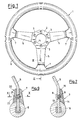
- a steering wheel 1 for motor vehicles has a central part 2 in which there are provided a central positioning hole 4 and a plurality of lateral fastening holes 3 for the application to the steering column of a motor vehicle. From the central part 2 there extends in a radial direction a plurality of spokes 5, which fit in a rim 6 at the other extremity. At the point wherein the spokes 5 meet the rim 6 there is provided a plurality of shaped plates 7 which cover the connecting areas between said spokes 5 and said rim 6.
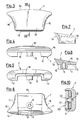
- These plates are shaped as shown in Fig.s from 3 to 8 and comprise an open external surface 10 having an inclined profile with rounded concave lateral sides 16 and an internal surface 11 interrupted by a groove 12 which extends along the entire height of the plate 7 and whose internal dimensions are equal to the external dimensions of a spoke at the junction point.
- a rise 13 in which there is obtained a drilled seat 9, in which the fastening screw 8 is screwed with its head reacting against the face of the spoke opposite that on which the plate rests.
- An extremity 14 is shaped so as to mate perfectly with the steering wheel's rim 6 (Fig. 2) so as not to cause a discontinuity in the shape.
- the other extremity 15 is in turn rounded and tapered so as to mate perfectly with the surface of the spoke 5 on which the plate 7 is fitted.
- the same plate of Fig.s 3-8 or one slightly different may be fastened to the respective spoke of the steering wheel by means of a complementary counter-plate 20, which together with the plate 7 embraces the spoke 5 in the area where it joins the rim 6.
- a fastening screw 21 having a conical head inserted in a suitable seat 22 of the counter-plate 20, with consequent further improvement in the aesthetics and in the maneuverability of the steering wheel.
- the plate described above may be applied to any steering wheel for motor vehicles, even if it is very different from that of Fig. 1, so as to hide from view the areas wherein dust or any manufacturing residues may accumulate, avoiding the necessity of an accurate cleaning in those areas.
- the curvilinear shape of the plate gives the steering wheel a greater practicality of use as it is of an anatomical type.
- the plate improves the aesthetics of the steering wheel itself as it constitutes a decorative element.
- Plate 7 may be of metallic material, and it is also possible with the occasion to provide a particular coating of this plate 7 to meet the different tastes of the motor car enthusiast.
Landscapes
- Engineering & Computer Science (AREA)
- Chemical & Material Sciences (AREA)
- Combustion & Propulsion (AREA)
- Transportation (AREA)
- Mechanical Engineering (AREA)
- Steering Controls (AREA)
Claims (5)
- Steuerrad für Kraftfahrzeuge mit einem Mittelteil (2), von dem sich eine Mehrzahl von radialen Speichen (5) erstreckt, die in einen äußeren kreisförmigen Lenkkranz (6) eingepaßt sind, dadurch gekennzeichnet, daß die äußeren Enden der Speichen (5) an ihren Verbindungsgebieten mit dem äußeren Lenkkranz (6) mit geformten, abdeckenden Platten (7) versehen sind.
- Steuerrad für Kraftfahrzeuge nach Anspruch 1,
dadurch gekennzeichnet, daß die Platten (7) eine äußere offene Oberfläche (10) mit einem geneigten Profil mit abgerundeten konkaven Seiten (16), die ästhetisch und funktionell zu der Form der radialen Speichen (5) und dem kreisförmigen Lenkkranz (6) passen, und eine innere Oberfläche (11), die von einer Pille (12) unterbrochen ist, die sich entlang der gesamten Höhe der Platte (7) erstreckt und deren innere Abmessungen gleich den äußeren Abmessungen einer Speiche (5) eines Steuerrades (1) aufweisen, wodurch Mittel (8; 20, 21) zum Befestigen der Platte (7) an den Speichen (5) vorgesehen werden. - Steuerrad für Kraftfahrzeuge nach Anspruch 2,
dadurch gekennzeichnet, daß die Befestigungsmittel (8; 20, 21) durch eine Schraube (8) dargestellt sind, deren Kopf gegen die Fläche der Speiche (5) wirkt, die der gegenüberliegt, auf der die Platte (7) ruht. - Steuerrad für Kraftfahrzeuge nach Anspruch 2,
dadurch gekennzeichnet, daß die Befestigungsmittel (8; 20, 21) eine Gegenplatte (20) aufweisen, die auf eine komplementäre Weise in Bezug auf die Platte (7) geformt ist und an die Fläche der Speiche (5) gelegt ist, die der gegenüberliegt, auf der die Platte (7) ruht, und eine Befestigungsschraube (21) deren Kopf in einem Sitz (22) der Gegenplatte (20) aufgenommen ist. - Steuerrad für Kraftfahrzeuge nach Anspruch 1,
dadurch gekennzeichnet, daß die Platten (7) aus metallischem Material sind.
Priority Applications (1)
| Application Number | Priority Date | Filing Date | Title |
|---|---|---|---|
| AT89202721T ATE92412T1 (de) | 1988-11-09 | 1989-10-26 | Lenkrad fuer kraftfahrzeuge mit befestigungsplatten zwischen speichen und felge. |
Applications Claiming Priority (2)
| Application Number | Priority Date | Filing Date | Title |
|---|---|---|---|
| IT2212288U | 1988-11-09 | ||
| IT8822122U IT215383Z2 (it) | 1988-11-09 | 1988-11-09 | Volante per autoveicoli con placchette di raccordo tra razze e corona. |
Publications (3)
| Publication Number | Publication Date |
|---|---|
| EP0368386A2 EP0368386A2 (de) | 1990-05-16 |
| EP0368386A3 EP0368386A3 (en) | 1990-09-26 |
| EP0368386B1 true EP0368386B1 (de) | 1993-08-04 |
Family
ID=11191820
Family Applications (1)
| Application Number | Title | Priority Date | Filing Date |
|---|---|---|---|
| EP89202721A Expired - Lifetime EP0368386B1 (de) | 1988-11-09 | 1989-10-26 | Lenkrad für Kraftfahrzeuge mit Befestigungsplatten zwischen Speichen und Felge |
Country Status (4)
| Country | Link |
|---|---|
| EP (1) | EP0368386B1 (de) |
| AT (1) | ATE92412T1 (de) |
| DE (1) | DE68908085T2 (de) |
| IT (1) | IT215383Z2 (de) |
Families Citing this family (2)
| Publication number | Priority date | Publication date | Assignee | Title |
|---|---|---|---|---|
| FR2774348B1 (fr) | 1998-02-04 | 2000-03-03 | Roulements Soc Nouvelle | Armature de volant a capteur de couple integre ou rapporte pour dispositif de direction de vehicule |
| JP7558759B2 (ja) * | 2020-11-05 | 2024-10-01 | Joyson Safety Systems Japan合同会社 | ステアリングホイールの芯金構造 |
Family Cites Families (3)
| Publication number | Priority date | Publication date | Assignee | Title |
|---|---|---|---|---|
| GB546935A (en) * | 1941-02-11 | 1942-08-06 | Joseph Duthie Birnie | Improvements in steering wheels |
| JPS60145965U (ja) * | 1984-03-10 | 1985-09-27 | 豊田合成株式会社 | ステアリングホイ−ル用芯材 |
| DE3509302A1 (de) * | 1985-03-15 | 1986-09-25 | Carl Kittel GmbH & Co KG, 8057 Eching | Lenkrad fuer kraftfahrzeuge |
-
1988
- 1988-11-09 IT IT8822122U patent/IT215383Z2/it active
-
1989
- 1989-10-26 DE DE89202721T patent/DE68908085T2/de not_active Expired - Fee Related
- 1989-10-26 EP EP89202721A patent/EP0368386B1/de not_active Expired - Lifetime
- 1989-10-26 AT AT89202721T patent/ATE92412T1/de not_active IP Right Cessation
Also Published As
| Publication number | Publication date |
|---|---|
| ATE92412T1 (de) | 1993-08-15 |
| IT215383Z2 (it) | 1990-09-11 |
| IT8822122V0 (it) | 1988-11-09 |
| DE68908085T2 (de) | 1993-12-16 |
| DE68908085D1 (de) | 1993-09-09 |
| EP0368386A3 (en) | 1990-09-26 |
| EP0368386A2 (de) | 1990-05-16 |
Similar Documents
| Publication | Publication Date | Title |
|---|---|---|
| US5286092A (en) | Decorative wheel cover for truck wheel | |
| US5820225A (en) | Vehicle wheel assembly and method of making same | |
| US7204562B2 (en) | Wheel clad assembly | |
| NO961513L (no) | Kjöretöyratt med et integrert holdersystem for kollisjonspute | |
| US6969124B2 (en) | Center cap for vehicle wheel | |
| US5205186A (en) | Steering wheel | |
| EP0368386B1 (de) | Lenkrad für Kraftfahrzeuge mit Befestigungsplatten zwischen Speichen und Felge | |
| CA2200820A1 (en) | Steering wheel overlay | |
| EP0232942B1 (de) | Radzierblende mit Befestigungsteilen zum Aufmontieren dieser an ein Kraftfahrzeugrad und seine entsprechende Radnabe | |
| JPS6151288U (de) | ||
| US5364172A (en) | Wheel and cover assembly with radiused standoff | |
| JPS6113361Y2 (de) | ||
| USD391912S (en) | Motor car wheel axle cap | |
| JPH0373273U (de) | ||
| JPH02138237U (de) | ||
| JPS5843458Y2 (ja) | 計器板用の飾り板 | |
| JPH0359873B2 (de) | ||
| JPH0241901A (ja) | プラスチックホイールカバー | |
| JPH0386801U (de) | ||
| JPS62115901U (de) | ||
| CA2017288A1 (en) | Steering wheel | |
| JPH0326002Y2 (de) | ||
| JPS62176075U (de) | ||
| JPS6191402U (de) | ||
| JPH01123503U (de) |
Legal Events
| Date | Code | Title | Description |
|---|---|---|---|
| PUAI | Public reference made under article 153(3) epc to a published international application that has entered the european phase |
Free format text: ORIGINAL CODE: 0009012 |
|
| AK | Designated contracting states |
Kind code of ref document: A2 Designated state(s): AT CH DE ES FR GB IT LI SE |
|
| PUAL | Search report despatched |
Free format text: ORIGINAL CODE: 0009013 |
|
| AK | Designated contracting states |
Kind code of ref document: A3 Designated state(s): AT CH DE ES FR GB IT LI SE |
|
| 17P | Request for examination filed |
Effective date: 19901123 |
|
| 17Q | First examination report despatched |
Effective date: 19920504 |
|
| GRAA | (expected) grant |
Free format text: ORIGINAL CODE: 0009210 |
|
| AK | Designated contracting states |
Kind code of ref document: B1 Designated state(s): AT CH DE ES FR GB IT LI SE |
|
| PG25 | Lapsed in a contracting state [announced via postgrant information from national office to epo] |
Ref country code: SE Effective date: 19930804 Ref country code: LI Effective date: 19930804 Ref country code: FR Effective date: 19930804 Ref country code: CH Effective date: 19930804 Ref country code: AT Effective date: 19930804 |
|
| REF | Corresponds to: |
Ref document number: 92412 Country of ref document: AT Date of ref document: 19930815 Kind code of ref document: T |
|
| ITF | It: translation for a ep patent filed | ||
| REG | Reference to a national code |
Ref country code: ES Ref legal event code: BA2A |
|
| REF | Corresponds to: |
Ref document number: 68908085 Country of ref document: DE Date of ref document: 19930909 |
|
| PG25 | Lapsed in a contracting state [announced via postgrant information from national office to epo] |
Ref country code: GB Effective date: 19931104 |
|
| REG | Reference to a national code |
Ref country code: CH Ref legal event code: PL |
|
| EN | Fr: translation not filed | ||
| PLBE | No opposition filed within time limit |
Free format text: ORIGINAL CODE: 0009261 |
|
| STAA | Information on the status of an ep patent application or granted ep patent |
Free format text: STATUS: NO OPPOSITION FILED WITHIN TIME LIMIT |
|
| GBPC | Gb: european patent ceased through non-payment of renewal fee |
Effective date: 19931104 |
|
| PG25 | Lapsed in a contracting state [announced via postgrant information from national office to epo] |
Ref country code: DE Effective date: 19940701 |
|
| 26N | No opposition filed | ||
| PG25 | Lapsed in a contracting state [announced via postgrant information from national office to epo] |
Ref country code: ES Free format text: LAPSE BECAUSE OF NON-PAYMENT OF DUE FEES Effective date: 19941027 |
|
| REG | Reference to a national code |
Ref country code: ES Ref legal event code: FA2A Effective date: 19970325 |
|
| PG25 | Lapsed in a contracting state [announced via postgrant information from national office to epo] |
Ref country code: IT Free format text: LAPSE BECAUSE OF NON-PAYMENT OF DUE FEES Effective date: 20051026 |