EP0367852B1 - Sectional rolling door - Google Patents
Sectional rolling door Download PDFInfo
- Publication number
- EP0367852B1 EP0367852B1 EP88118600A EP88118600A EP0367852B1 EP 0367852 B1 EP0367852 B1 EP 0367852B1 EP 88118600 A EP88118600 A EP 88118600A EP 88118600 A EP88118600 A EP 88118600A EP 0367852 B1 EP0367852 B1 EP 0367852B1
- Authority
- EP
- European Patent Office
- Prior art keywords
- door
- elements
- piece
- sectional
- guide
- Prior art date
- Legal status (The legal status is an assumption and is not a legal conclusion. Google has not performed a legal analysis and makes no representation as to the accuracy of the status listed.)
- Expired - Lifetime
Links
Images

Classifications
-
- E—FIXED CONSTRUCTIONS
- E05—LOCKS; KEYS; WINDOW OR DOOR FITTINGS; SAFES
- E05D—HINGES OR SUSPENSION DEVICES FOR DOORS, WINDOWS OR WINGS
- E05D15/00—Suspension arrangements for wings
- E05D15/16—Suspension arrangements for wings for wings sliding vertically more or less in their own plane
- E05D15/24—Suspension arrangements for wings for wings sliding vertically more or less in their own plane consisting of parts connected at their edges
- E05D15/244—Upper part guiding means
- E05D15/246—Upper part guiding means with additional guide rail for producing an additional movement
-
- E—FIXED CONSTRUCTIONS
- E05—LOCKS; KEYS; WINDOW OR DOOR FITTINGS; SAFES
- E05D—HINGES OR SUSPENSION DEVICES FOR DOORS, WINDOWS OR WINGS
- E05D15/00—Suspension arrangements for wings
- E05D15/06—Suspension arrangements for wings for wings sliding horizontally more or less in their own plane
- E05D15/12—Suspension arrangements for wings for wings sliding horizontally more or less in their own plane consisting of parts connected at their edges
-
- E—FIXED CONSTRUCTIONS
- E05—LOCKS; KEYS; WINDOW OR DOOR FITTINGS; SAFES
- E05D—HINGES OR SUSPENSION DEVICES FOR DOORS, WINDOWS OR WINGS
- E05D13/00—Accessories for sliding or lifting wings, e.g. pulleys, safety catches
- E05D13/10—Counterbalance devices
- E05D13/12—Counterbalance devices with springs
- E05D13/1207—Counterbalance devices with springs with tension springs
- E05D13/1215—Counterbalance devices with springs with tension springs specially adapted for overhead wings
-
- E—FIXED CONSTRUCTIONS
- E05—LOCKS; KEYS; WINDOW OR DOOR FITTINGS; SAFES
- E05Y—INDEXING SCHEME RELATING TO HINGES OR OTHER SUSPENSION DEVICES FOR DOORS, WINDOWS OR WINGS AND DEVICES FOR MOVING WINGS INTO OPEN OR CLOSED POSITION, CHECKS FOR WINGS AND WING FITTINGS NOT OTHERWISE PROVIDED FOR, CONCERNED WITH THE FUNCTIONING OF THE WING
- E05Y2800/00—Details, accessories and auxiliary operations not otherwise provided for
- E05Y2800/10—Additional functions
- E05Y2800/12—Sealing
-
- E—FIXED CONSTRUCTIONS
- E05—LOCKS; KEYS; WINDOW OR DOOR FITTINGS; SAFES
- E05Y—INDEXING SCHEME RELATING TO HINGES OR OTHER SUSPENSION DEVICES FOR DOORS, WINDOWS OR WINGS AND DEVICES FOR MOVING WINGS INTO OPEN OR CLOSED POSITION, CHECKS FOR WINGS AND WING FITTINGS NOT OTHERWISE PROVIDED FOR, CONCERNED WITH THE FUNCTIONING OF THE WING
- E05Y2800/00—Details, accessories and auxiliary operations not otherwise provided for
- E05Y2800/26—Form, shape
- E05Y2800/27—Form, shape profiles
-
- E—FIXED CONSTRUCTIONS
- E05—LOCKS; KEYS; WINDOW OR DOOR FITTINGS; SAFES
- E05Y—INDEXING SCHEME RELATING TO HINGES OR OTHER SUSPENSION DEVICES FOR DOORS, WINDOWS OR WINGS AND DEVICES FOR MOVING WINGS INTO OPEN OR CLOSED POSITION, CHECKS FOR WINGS AND WING FITTINGS NOT OTHERWISE PROVIDED FOR, CONCERNED WITH THE FUNCTIONING OF THE WING
- E05Y2900/00—Application of doors, windows, wings or fittings thereof
- E05Y2900/10—Application of doors, windows, wings or fittings thereof for buildings or parts thereof
- E05Y2900/106—Application of doors, windows, wings or fittings thereof for buildings or parts thereof for garages
Landscapes
- Engineering & Computer Science (AREA)
- Mechanical Engineering (AREA)
- Support Devices For Sliding Doors (AREA)
- Gates (AREA)
- Elevator Door Apparatuses (AREA)
- Securing Of Glass Panes Or The Like (AREA)
- Special Wing (AREA)
- Wing Frames And Configurations (AREA)
Abstract
Description
Die Erfindung betrifft ein Sektionaltor mit den Merkmalen des Oberbegriffs von Patentanspruch 1.The invention relates to a sectional door with the features of the preamble of
Ein Sektionaltor mit diesen Merkmalen ist in der CH-A 343 624 beschrieben.A sectional door with these features is described in CH-A 343 624.
Die DE-U-8703 826 beschreibt ein Schiebetor, das aus Blättern oder Elementen ausgebildet ist, die durch elastische Verbindungsglieder gelenkig miteinander verbunden sind.DE-U-8703 826 describes a sliding gate which is formed from leaves or elements which are connected to one another in an articulated manner by elastic connecting members.
Aus dem Stand der Technik sind fernerhin Sektionaltore bekannt, die aus einer Anzahl die jeweilige Toröffnung verschließender und über Laufrollen in tor- und raumseitigen Laufschienen öffnend und schließend geführten, durch Verbindungsglieder schwenkbar miteinander verbundenen, Torelementen bestehen.Sectional doors are also known from the prior art, which consist of a number of gate elements which close the respective gate opening and are guided and guided via rollers in gate and room-side rails, and pivotably connected to one another by connecting elements.
Um nun das bei der Schließbewegung letzte Torelement in eine von den vorherlaufenden Torelementen bereits eingenommene Schließstellung zu bringen, war es bei dem vorgenannten Stand der Technik erforderlich, die endseitig des letzten Torelements angeordnete Laufrolle getrennt von den anderen Laufrollen in einer zweiten raumseitigen Laufschiene zu führen, die dann toröffnungsseitig endet oder in eine torseitige zweite Kurvenbahn übergehend endet.In order to bring the last door element during the closing movement into a closed position already assumed by the preceding door elements, it was necessary in the above-mentioned prior art to guide the roller arranged at the end of the last gate element separately from the other rollers in a second rail on the room side. which then ends on the gate opening side or ends in a second curve path on the door side.
Diesen und allen anderen Lösungen aus dem Stand der Technik ist gemeinsam, daß sie eine verhältnismässig große Kurve mit einem Radius von etwa 200 bis 300 mm benötigen, um unter die Garagen- oder Hallendecke oder an die Seitenwand zu gelangen.These and all other solutions from the prior art have in common that they require a relatively large curve with a radius of about 200 to 300 mm in order to get under the garage or hall ceiling or on the side wall.
In vielen Fällen reicht allerdings die Sturzhöhe oder die seitlich Mauerversetzung nicht aus, um bei geschlossenem Tor zu einem geraden Torabschluß zu gelangen, da der Radius der Kurve in die Toröffnung läuft. In diesen Fällen ist eine feststehende oder bewegliche Blende in der Toröffnung am Sturz oder neben der Laibung notwendigerweise erforderlich, um einen ebenflächigen Torabschluß zu erzielen.In many cases, however, the lintel height or the lateral wall offset is not sufficient to achieve a straight gate closure when the gate is closed, since the radius of the Curve runs into the gate opening. In these cases, a fixed or movable screen in the door opening at the lintel or next to the reveal is necessary to achieve a level door finish.
Um mit kleinstem Raumbedarf auszukommen, ist bekannt, sogenannte Doppelkurven vorzusehen. Ebenso werden auch die letzten Laufrollen am Tor dann mit besonderen Lagerböcken ausgestattet, damit dieser Teil des Tores beim Schließvorgang eine schnelle sowie kurze Schwenkbewegung ausführt, um das Tor zu schließen und eine ebene Torfläche herzustellen.In order to get by with the smallest space requirement, it is known to provide so-called double curves. Likewise, the last rollers on the door are then equipped with special bearing blocks so that this part of the door swings quickly and briefly during the closing process in order to close the door and create a flat door surface.
Trotz dieser bekannten Maßnahmen und technisch aufwendigen Lösungen konnte der Platzbedarf am Sturz oder in der Laibung nicht befriedigend begrenzt werden.Despite these known measures and technically complex solutions, the space required at the lintel or in the reveal could not be satisfactorily limited.
Der vorliegenden Erfindung liegt deshalb die Aufgabe zugrunde, ein Decken- oder Seitensektionaltor der eingangs genannten Art so weiterzubilden, daß ein wesentlich geringerer konstruktiver Aufwand notwendig ist, wobei zudem noch zum Beispiel eine geringere Sturzhöhe angestrebt wird.The present invention is therefore based on the object of developing a ceiling or side sectional door of the type mentioned at the outset in such a way that a substantially lower design effort is necessary, with a lower lintel height also being sought, for example.
Die Lösung dieser Aufgabe erfolgt durch die Merkmale von Patentanspruch 1.This object is achieved by the features of
Hierdurch entfällt gegenüber dem zuletzt diskutierten Stand der Technik die zweite raumseitige Laufschiene; stattdessen schließt sich nach vorn ein Bogenstück an, das in die torseitige Laufschiene einmündet. Damit ergibt sich der wesentliche Vorteil, daß lediglich eine einzige raumseitige Laufschiene verwendet werden muß, und daß der konstruktive Aufbau im Torbereich einfacher gestaltet ist.Compared to the state of the art discussed last, this eliminates the second track on the room side; instead, there is an arch section that opens into the door-side track. This results in the essential advantage that only a single track on the room side has to be used and that the structural design in the gate area is simpler.
Mit dieser erfindungsgemässen Maßnahme wird der weitere Vorteil erreicht, daß lediglich eine Sturzhöhe von 40 bis 50 mm gegenüber einer Sturzhöhe von etwa 200 bis 250 mm beim Stand der Technik erforderlich ist.With this measure according to the invention the further advantage is achieved that only a lintel height of 40 to 50 mm compared a lintel height of approximately 200 to 250 mm is required in the prior art.
In einer erfindungsgemäßen Ausführungsform ist vorgesehen, daß die Laufschienen in einem zum Torblatt hin offenen U-Profil ausgeführt sind, die inneren Schenkel der U-Profile des jeweiligen beidseitig angeordneten Laufschienen-Paares im Bereich des Bogenstücks über die einen großen Radius aufweisende und die Laufrollen durch die Rückstellkraft der Verbindungselemente oder Sicken innen anliegend umlenkende Führungsbahn miteinander verbunden sind, während die äußeren Schenkel des jeweiligen Laufschienen-Paares im Bereich des Bogenstücks über die einen wesentlich kleineren Radius aufweisende und die endseitige Laufrolle innen anliegend führende Kurvenbahn miteinander verbunden sind, und das diese endseitige Laufrolle des hinteren Abschluß-Torelements in die und aus der Schließstellung führende Umlenk- und Arretierstück eine parallel sowie abständlich einlaufseitig der Kurvenbahn verlaufende Laufrollenführung und eine dem Radius gegenüberliegende und nach innen abgewinkelte Arretierkante aufweist.In one embodiment according to the invention it is provided that the running rails are designed in a U-profile which is open towards the door leaf, the inner legs of the U-profiles of the respective pair of running rails arranged on both sides in the region of the curved piece via the large radius and the running rollers the restoring force of the connecting elements or beads on the inside of the deflecting guide track are connected to one another, while the outer legs of the respective pair of running tracks are connected to one another in the area of the curved piece via the cam track having a substantially smaller radius and the leading roller on the inside, and this ends-side Roller of the rear end gate element in and out of the closed position leading and locking piece a parallel and spaced inlet side of the cam track running roller guide and a radius opposite and inward has an angled locking edge.
Die Erfindung wird nun anhand von Ausführungsbeispielen mit Bezug auf die anliegenden Zeichnungen näher beschrieben, aus denen sich weitere wichtige Merkmale ergeben.The invention will now be described in more detail using exemplary embodiments with reference to the accompanying drawings, from which further important features result.
In den Zeichnunge zeigt -
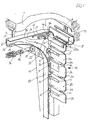
Figur 1- schematisch in einer Perspektivansicht ein aus einem einstückigen Torblatt bestehendes Decken-Sektionaltor in der Schließstellung, wobei die hintere Laufrolle in der Arretierstellung gegen die Arretierfläche des Bogenstücks anliegt;
Figur 2- die Perspektivansicht der
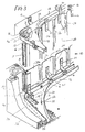
Figur 1 mit dem Decken-Sektionaltor kurz vor Erreichen der Schließstellung; Figur 3- schematisch in einer Perspektivansicht ein aus einem einstückigen Torblatt bestehendes Seiten-Sektionaltor in der Schließstellung, wobei die hintere Laufrolle in der Arretierstellung gegen die Arretierfläche des Bogenstücks anliegt;
- Figure 1
- schematically in a perspective view of a one-piece door leaf overhead sectional door in the closed position, the rear roller in the locking position against the locking surface of the arch piece;
- Figure 2
- the perspective view of Figure 1 with the overhead sectional door just before reaching the closed position;
- Figure 3
- schematically in a perspective view of a one-piece door leaf side sectional door in the closed position, the rear roller resting in the locking position against the locking surface of the arch piece;
Die Laufrollen-Führungselemente bestehen hier aus einer raumseitigen, horzontalen Laufschiene 2, die über ein Befestigungselement 7 an der Garagendecke 1 festgelegt ist, einer torseitigen, vertikalen Laufschiene 13, die in nicht dargestellter Form frontseitig und am Boden festgelegt ist, und einem die beiden Laufschienen 13 und 2 verbindenden Bogenstück 19. Diese drei Führungselemente können als einstückig ausgebildete rechte und, spiegelbildlich, linke Baugruppe zusammengefaßt sein. Die Laufschienen 2, 13 bestehen in den gezeigten Ausführungsformen aus einem zum Türelement hin offen angeordneten U-Profil.The roller guide elements consist here of a room-side,
Aus den Figuren 1 und 2 geht deutlich hervor, daß der äußere Schenkel 25 der raumseitigen, horizontalen Laufschiene 2 in eine einen verhältnismäßig kleinen Radius aufweisende Kurvenbahn 14 des Bogenstücks 19, und von dort zum äußeren Schenkel der torseitigen, vertikalen Laufschiene 13 nahtlos übergeht. Der innere Schenkel 26 der Laufschiene 2 geht hingegen in eine einen großen Radius aufweisende Führungsbahn 22 des Bogenstücks 19, und von dort zum inneren Schenkel der torseitigen Laufschiene 13 nahtlos über.From Figures 1 and 2 it is clear that the
Das Bogenstück 19 weist ferner entlang des einlaufseitigen Bereichs der Kurvenbahn 14 ein Umlenk- und Arretierungsstück 3 mit einer parallel und abständlich zu dieser verlaufenden Laufrollenführung 27 und einer torseitig daran ansetzenden, nach innen abgewinkelten Arretierkante 28 auf.The
Das in den Zeichnungsfiguren 1 bis 3 dargestellte Torelement oder einteilige Torblatt 10 ist durch Sicken 24 in Sektionen 20 unterteilt, wobei die Sicken 24 die Elastizität des Torblattes sicherstellen und im Kurvenbereich des Bogenstücks 19 die erforderliche Rückstellkraft erzeugen.The door element or one-
Das einstückige Torblatt 10 kann beispielsweise in einer bevorzugten Ausführungsform aus Blech bestehen, das über die Breite eingeformt, dieses Torblatt 10 in Sektionen 20 unterteilende Vertiefungen oder Sicken 24 aufweist, die dem Torblatt in diesen Bereichen 24 die erforderliche Elastizität und Rückstellkraft verleihen.In one preferred embodiment, the one-
Wie aus den Figuren 1 bis 3 ersichtlich, sind den Sektionen oder einzelnen Torelementen 20 jeweils beidseitig Laufrollen 4 zugeordnet, die frei drehbar an Lagerbügeln 11 und mittels diesen an den Sektionen bzw. Torelementen befestigt sind. Diese Laufrollen 4 rollen innenseitig des inneren Schenkels 26 der Laufschienen-U-Profile ab, wobei die Laufrollen 4 bei einem zur Decke öffnenden Sektionaltor im horizontalen Bereich der Laufschienen gleichzeitig die das Tor tragenden Elemente sind, während bei dem zur Seite öffnenden Sektionaltor als Tragelemente an den Sektionen/Torelementen 20 anstelle jeder zweiten oder dritten Laufrolle 4 jeweils oben Tragrollen 31 vorgesehen sind, die außenseitig der Basis der oberen Laufschienen-U-Profile abrollen.As can be seen from FIGS. 1 to 3, the sections or
Dem zur Decke öffnenden Sektionaltor sind zur seitlichen Führung des Tores beidseitig zwei oder mehr Führungsrollen 30 zugeordnet, die jeweils an einer am Torelement bzw. der Torsektion befestig-Platte 12 drehbar gelagert sind, wobei in dieser Führungsrollen-Position die jeweilige Laufrolle 4 ebenfalls an dieser Platte 12 drehbar gelagert ist. Diese Führungsrollen 30 rollen innenseitig an der Basis des Laufschienen-U-Profils ab und bewirken damit die seitliche Führung des Decken-Sektionaltores.The sectional door opening to the ceiling is assigned two or
In der Figur 1 ist eine Decken-Sektionaltor in der Schließstellung des Tores dargestellt. Das Torblatt 10 ist einstückig ausgebildet. Parallel zueinander und über die gesamte Breite des Torblattes 10 verlaufend sind hier Sicken 24 vorgesehen, die einerseits das Torblatt 10 in an sich mehr oder weniger starre Sektionen 20 aufteilt, andererseits dem Torblatt 10 über die Breite die angestrebte Steifigkeit und senkrecht dazu die erforderliche Elastizität und Rückstellkraft verleiht.1 shows a sectional overhead door in the closed position of the door. The
In der Schließstellung des Tores (Figur 1) bilden die Sektionen 20 des Torblattes 10 eine senkrechte ebene Fläche. Die der oberen Sektion 20a endseitig zugeordnete obere Laufrolle 4a liegt hier gegen die Arretierkante 28 des Umlenk- und Arretierungsstücks 3 unmittelbar innenseitig der Kurvenbahn 14 an, in die sie in der Endbewegung beim Schließvorgang in Pfeilrichtung 34 (Figur 2) über die Laufrollenführung 27 gelenkt wurde und damit die obere oder letzte Sektion 20a sowie die unmittelbar benachbarte Sektion 20 mittels der durch die Sicken 24 in das Torblatt eingebrachten Rückstellkräfte in einer Ebene mit den anderen Sektionen 20 ausrichtete.In the closed position of the gate (Figure 1), the
Aus der Offenstellung, mit den Laufrollen 4, 4a innenseitig des unteren U-Profilschenkels 26 der raumseitigen oder horizontalen Laufschiene 2 (Fig.1 u.2) auflagernd, zur Schließstellung, wird in der Anfangsbewegung die durch die Rückstellkräfte gegen die Kurvenbahn 14 innenseitig anliegende und der ersten oder vorderen Sektion 20 des Torblattes 10 zugeordnete Laufrolle 4 entlang des vorderen oder außenseitigen Schenkels 25 der torseitig vertikalen Laufschiene 13 abrollen. Durch den sektionsweisen Übergang des Torblattes von der horizontalen Laufschiene 2 über das Bogenstück 19 in wie vertikale Laufschiene 13 werden die nachfolgenden, den entsprechenden Sektionen 20 zugeordneten Laufrollen 4 durch die mittels der Sicken 24 in das Torblatt 10 eingebrachten Rückstellkräfte zwangsweise innenseitig der Führungsbahn 22 abrollen, wobei allerdings die letzte oder endseitige Laufrolle 4a vor dem Einlauf in das Bogenstück 19 innenseitig des außenseitigen U-Schenkels 25 der Laufschiene 2 abrollend durch die Rückstellkräfte zwangsweise entlang des zur Kurvenbahn 14 führenden Schenkels und über die Laufrollenführung 27 in Pfeilrichtung 34 (Figur 2) in die Endstellung geleitet wird. Wie aus den Figuren ersichtlich, bildet die letzte Sektion 20a in der Endstellung der Laufrolle 4a mit den übrigen Sektionen eine ebene Torfläche. Es ist auch dargestellt, daß die Laufrolle 4 der dieser Endsektion 20a benachbarten Torsektion 20 in der Endphase der Schließbewegung als auch der Anfangsphase der Öffnungsbewegung durch die Rückstellkräfte nicht über die ganze Länge an der Führungsbahn 22 abrollt, sondern eher einen Weg beschreibt, wie es die Pfeile 35 (Figur 2) bzw. 33 (Figur 1) in etwa darstellen. Die in den Figuren 1 und 2 dargestellten Anordnungen befinden sich in spiegelbildlicher Ausführung selbstverständlich auch auf der gegenüberliegenden Seite des Tores bzw. der Toröffnung.From the open position, with the
Für das zur Decke öffnende Sektionaltor ist z.B. eine Flaschenzug-Hubmechanik 16 mit Federnpaket 36 und Umlenkrolle 37 für ein Zugseil 17 als Gewichtsausgleich für ein handbedientes Tor an beiden Seiten des Tores vorgesehen. Das Zugseil 17 kann einerseits an der untersten Sektion 20 des Torblattes 10 festgelegt sein, sodaß hier in der Endphase der Öffnungsbewegung, entgegen der vorhergehend beschriebenen Bewegungsrichtung der unteren Laufrolle 4 innenseitig entlang des außenseitigen Schenkels der vertikalen Laufschiene 13 in das Bogenstück und zur Kurvenbahn 14, diese untere Laufrolle 4 durch das Seil 17 auf der Führungsbahn 22 gehalten und der die Öffnungsbewegung stoppende Anschlag am raumseitigen Ende der horizontalen Laufschiene 2 vorgesehen wird. Andererseits kann das Zugseil 17 an der zweiten oder dritten Torsektion 20 von vorn ansetzen, wobei die Laufrolle 4 der vorderen Torsektion 20 durch die Rückstellkräfte, wie bereits beschrieben, zur Endstellung Kurvenbahn 14 gelangt und die vordere Torsektion 20 zur Freigabe der vollen Nutzhöhe in die Horizontale schwenkt.For the sectional door opening to the ceiling, e.g. a block and
Der oberen Endsektion 20a und der unteren Endsektion (nicht dargestellt) sind Abschlußprofile zugeordnet, wobei das obere Abschlußprofil 8 zur Abdichtung in der Torschließstellung eine Bürstenleiste 9 aufweist, die in Kontakt mit z. B. einer am Sturz 15 über ein Befestigungselement 6 angeordneten Blende 5 ist (Figur 1 u.2). Beide Abschlußprofile erstrecken sich über die gesamte Breite des Tores, wobei zur seitlich abständlichen Führung des Tores die bereits erwähnten Führungsrollen 30 vorgesehen sind, und zur sicheren Führung der Laufrollen 4 zumindest im horizontalen Bereich der innere Schenkel 26 der Laufschiene 2 nach innen abgewinkelt eine Führungskante 29 ausbildet.The
Die Figur 3 zeigt ein zur Seite öffnendes Rundlauf-Sektionaltor in der Schließstellung. Dargestellt ist wiederum ein einstückig ausgeführtes Torblatt 10 mit Sicken 24, wobei jeder Sektion 20 des Torblattes beidseitig je eine Laufrolle 4 zugeordnet ist. Wie bei dem vorbeschriebenen Decken-Sektionaltor sind zwei Laufschienen-Anordnungen mit raumseitiger Laufschiene 2 und torseitiger Laufschiene 13 sowie diese verbindendem Bogenstück 19 vorhanden, wobei die eine Laufschienen-Anordnung über der Toröffnung mittels entsprechenden Befestigungselementen und die andere Laufschienen-Anordnung am Boden festgelegt ist. Die Führung des Torblattes 10 erfolgt in den Laufschienen ebenfalls mittels Laufrollen 4, während die erforderliche Aufhängung des Torblattes über Tragrollen 31 erfolgt, welche zum Beispiel anstelle einer oberen Laufrolle 4 an den Sektionen 20 über ein Tragelement 38 befestigt sind. Diese Tragrollen 31 rollen außenseitig der Basis der oberen U-förmigen Laufschienen 2, 13 und dem oberen Bogenstück 19 bei der Öffnungs- und Schließbewegung des Tores.FIG. 3 shows a rotary sectional door opening to the side in the closed position. Again, a one-piece design is shown
Wesentlich ist auch bei diesem Seiten-Sektionaltor, daß in der gezeigten Schließstellung die raumseitige oder hintere Laufrolle 4a am Abschlußprofil 8 bei der Öffnungsbewegung aus der dargestellten Stellung an der Arretierkante 28 gegen die Kurvenbahn 14 anlaufend in Pfeilrichtung 32 gegen die Rückstellkräfte der Sicken 24 ausgelenkt und am außenseitigen Schenkel 25 abrollend in die raumseitige ein U-Profil aufweisende Laufschiene 2 einläuft. Die nächstfolgenden Laufrollen 4 laufen hingegen in Richtung des Pfeiles 33 entlang der Führungsbahn 22 in die raumseitige Laufschiene 2 ein. Es versteht sich mit Bezug auf die Erläuterungen zum Decken-Sektionaltor von selbst, daß in der Endphase der Schließbewegung die endseitig angeordnete Laufrolle 4a durch die Rückstellkräfte entlang des äußeren Schenkels 25 in die in Figur 1 als auch 3 dargestellte Endstellung geführt wird, wobei die Laufrollenführung 27 des im Bogenstück 19 befestigten Umlenkelements 3 sicherstellt, daß diese Laufrolle 4a durch die bei der nur kleinen Schwenkbewegung der Endsektion 20a in gleiche Ebene mit den anderen Sektionen 20 nachlassenden Rückstellkräfte nicht in Richtung auf die Führungsbahn 22 abweichen kann.It is also important in this side sectional door that in the closed position shown, the room-side or
Dem Decken- als auch dem Seiten-Sektionaltor kann ein Elektro-Antrieb zugeordnet werden, der mit einer Schubstange mittig des Torblattes am Abschlußprofil 8 des raumseitigen oder oberen Ende angelenkt ist. Bei einem solchen Torantrieb kann zum Beispiel auch das Umlenk- und Arretierungstück 3 im Bogenstück 19 entfallen, da die Schubstange bei der Einleitung der Öffnungsbewegung die obere oder raumseitige Torsektion 20a aus der Ebene mit den anderen Sektionen 20 auslenkt, die endseitige Laufrolle 4a in die raumseitige Laufschiene 2 führt, und damit die nachfolgenden Laufrollen 4 auf die Führungsbahn 22 drückt und in die Laufschiene 2 zieht. In der umgekehrten Schließrichtung drückt in der Endphase der Schließbewegung die Schubstange des Elektroantriebs die endseitige Laufrolle 4a in die Kurvenbahn 14, wodurch auch die letzte Torsektion 20a in eine Ebene mit den anderen Sektionen 20 einschwenkt. Ein Torantrieb dieser Art ist an sich bekannt und wurde daher in den Zeichnungsfiguren nicht dargestellt.An electric drive can be assigned to the overhead as well as the side sectional door, which is articulated with a push rod in the middle of the door leaf on the
Claims (9)
- A sectional door for use as a garage door or the like opening towards the roof or to the side, consisting of a number of door elements (20), closing the respective door opening and guided in an opening and closing manner over runners (4, 4a) in guide rails (2) on the door- and room side, in which the guide rails (2) on the room side, provided in each case on both sides of the sectional door, are constructed as single-track individual rails to receive the runners (4,4a) supported via bearing brackets (11 )in the opened state of the sectional door on the door leaves or door elements (20) on both sides, for the transition from the respective guide rail (2) on the room side to the guide rail (13) on the door side, a curved piece (19) forming an angle of approximately 90 degrees and an outer curved path (14) is provided with a deflecting- and arresting piece (3), deflecting in the closed position of the door the rear runner (4a) associated with the closure door element (20a) and with a guide path (22) deflecting the other runners (4) from one guide rail to the other,
characterised in that
the leaves or elements (20) forming the sectional door are connected with each other by elastic connecting members (23) in the form of longitudinal or transverse corrugations (24) aligning these elements in one plane and restoring them into the plane, in which the corrugations (24) form parts which are in one piece of material with the elements (20). - A sectional door according to Claim 1, characterised in that the leaves or elements forming this door are sections (20) of a door leaf (10) closing the door opening in one piece in the closed position, which door leaf (10) is constructed so as to be elastically yielding by corrugations (24) dividing into sections (20) and running over the entire width.
- A sectional door according to Claim 1 to 2, characterised in that the guide rails (2,13) are constructed in a U-section open to the door leaf (10), the inner shanks (26) of the U-sections of the respective pair of guide rails (2,13) arranged on both sides are connected with each other in the region of the curved piece (19) via the guide path (22), having a large radius and deflecting the runners (4) through the restoring force of the corrugations (24) attached on the inside, whilst the outer shanks (25) of the respective pair of guide rails (2,13) in the region of this curved piece (19) are connected with each other via the curved path (14) , having a substantially smaller radius and guiding the runner (4a) attached on the inside, and the deflecting- and arresting piece (3), guiding this runner (4a) of the rear closure door element (20a) into and out of the closed position, has a runner guide (27) running parallel and at a distance on the inlet side of the curved path (14) and also has an arresting edge (28) lying oposite the radius and angled inwards.
- A sectional door according to Claim 1 to 3, characterised in that the inner shank (26) of the guide rail (2) as runner guide edge (29) is angled towards the other shank (25).
- A sectional door according to Claim 1 to 4, characterised in that at the upper or room-side end of the door leaf (10), consisting of individual door elements or divided into sections (20), a U-section (8), spanning the entire width, is provided as closure, which is arranged at both ends on the front side in each case, rotatably supporting the runner (4a), which is guided forcibly by the deflecting- and arresting piece (3), and rolling on the curved path (14) and on the inner side of the shank (25), and which U-section (8) for the tight closure of the door in closed position has a sealing brush (9) extending over the entire width and directed outwards.
- A sectional door according to Claim 1 to 5, characterised in that one or more sections or door elements (20) of the door have associated therewith a plate (12) receiving the bearing bracket (11) with the runner (4) and supporting a lateral guide roller (30).
- A sectional door according to Claim 1 to 5, characterised in that one or more sections or door elements (20) of the door,which opens to the side, have support elements (38), embracing the upper guide rails (2,13), with rollers (31) supported rotatably thereon, instead of runners (4), in whereby the rollers (31), carrying the door, roll on the outer base side of the U-sections of the guide rails (2, 13).
- A sectional door according to one of Claims 1 to 6, characterised in that the sectional door, opening toward the roof has, for a balance of weight, a pulley lifting mechanism (16) with a set of springs (36) and deflection roller (37) on both sides for a hauling cable (17) fixed to a lower door element (20).
- A sectional door according to one of Claims 1 to 7, characterised in that a self- arresting electric drive is associated with the door leaf (10), the push rod of which is articulated centrally to the door leaf (10) on the closure section (8) on the end-side or room side such that the closing and opening movements of the door element (20a) on the end side can take place in and out of the plane with the other elements (20) without a guide- and arresting edge (27,28) for the runner (4a).
Priority Applications (5)
| Application Number | Priority Date | Filing Date | Title |
|---|---|---|---|
| EP88118600A EP0367852B1 (en) | 1988-11-09 | 1988-11-09 | Sectional rolling door |
| AT88118600T ATE92999T1 (en) | 1988-11-09 | 1988-11-09 | SECTIONAL DOOR AS CIRCULAR DOOR. |
| DE8888118600T DE3883242D1 (en) | 1988-11-09 | 1988-11-09 | SECTIONAL DOOR AS A ROTARY GATE. |
| ES88118600T ES2045063T3 (en) | 1988-11-09 | 1988-11-09 | SECTION DOOR. |
| PT90190A PT90190B (en) | 1988-11-09 | 1989-04-04 | DOOR CONSTRUED BY SECTIONS AND FUNCTIONING AS A DOOR |
Applications Claiming Priority (1)
| Application Number | Priority Date | Filing Date | Title |
|---|---|---|---|
| EP88118600A EP0367852B1 (en) | 1988-11-09 | 1988-11-09 | Sectional rolling door |
Publications (2)
| Publication Number | Publication Date |
|---|---|
| EP0367852A1 EP0367852A1 (en) | 1990-05-16 |
| EP0367852B1 true EP0367852B1 (en) | 1993-08-11 |
Family
ID=8199542
Family Applications (1)
| Application Number | Title | Priority Date | Filing Date |
|---|---|---|---|
| EP88118600A Expired - Lifetime EP0367852B1 (en) | 1988-11-09 | 1988-11-09 | Sectional rolling door |
Country Status (5)
| Country | Link |
|---|---|
| EP (1) | EP0367852B1 (en) |
| AT (1) | ATE92999T1 (en) |
| DE (1) | DE3883242D1 (en) |
| ES (1) | ES2045063T3 (en) |
| PT (1) | PT90190B (en) |
Cited By (1)
| Publication number | Priority date | Publication date | Assignee | Title |
|---|---|---|---|---|
| DE202006017312U1 (en) * | 2006-11-10 | 2008-03-13 | Rehau Ag + Co | closure assembly |
Families Citing this family (9)
| Publication number | Priority date | Publication date | Assignee | Title |
|---|---|---|---|---|
| DE4031388C2 (en) * | 1990-10-04 | 1993-10-21 | Erich Doering | Side sectional door or rotary door, ceiling sectional door |
| US5425409A (en) * | 1993-12-17 | 1995-06-20 | Guia; Armando E. | Door mounting system |
| DE19637919C2 (en) * | 1996-09-17 | 2000-05-31 | Doering Normstahl Werk | Ceiling or side run sectional door |
| ES2245023T3 (en) * | 1997-01-10 | 2005-12-16 | Hormann Kg Brockhagen | ARTICULATED ROOF DOOR FOR PARTICULARLY LOW DINTELS. |
| AT503260B1 (en) * | 2006-02-16 | 2008-06-15 | Mewald Franz Ing | SECTIONAL |
| IT201700104198A1 (en) * | 2017-09-18 | 2019-03-18 | Flavio Martinelli | SECTIONAL DOOR WITH SLIDE ON MONOGUID |
| USD896616S1 (en) | 2018-03-22 | 2020-09-22 | Clopay Building Products Company, Inc. | Garage door cam |
| US11105133B2 (en) * | 2018-04-17 | 2021-08-31 | Clopay Building Products Company, Inc. | High-speed sectional door |
| CN113064104A (en) * | 2021-03-17 | 2021-07-02 | 安徽莱特实业集团有限公司 | Full-automatic transformation ratio and direct current resistance testing device |
Family Cites Families (3)
| Publication number | Priority date | Publication date | Assignee | Title |
|---|---|---|---|---|
| US2573962A (en) * | 1949-05-25 | 1951-11-06 | Earl C Fox | Sectional door |
| CH343624A (en) * | 1955-03-09 | 1959-12-31 | Morrison Steel Products Inc | Articulated door running in guide rails |
| DE8703826U1 (en) * | 1987-03-13 | 1987-04-30 | Max Meir "Rundum"-Garagentore Und Wetterschutz, 8898 Schrobenhausen, De |
-
1988
- 1988-11-09 EP EP88118600A patent/EP0367852B1/en not_active Expired - Lifetime
- 1988-11-09 DE DE8888118600T patent/DE3883242D1/en not_active Expired - Lifetime
- 1988-11-09 AT AT88118600T patent/ATE92999T1/en not_active IP Right Cessation
- 1988-11-09 ES ES88118600T patent/ES2045063T3/en not_active Expired - Lifetime
-
1989
- 1989-04-04 PT PT90190A patent/PT90190B/en not_active IP Right Cessation
Cited By (1)
| Publication number | Priority date | Publication date | Assignee | Title |
|---|---|---|---|---|
| DE202006017312U1 (en) * | 2006-11-10 | 2008-03-13 | Rehau Ag + Co | closure assembly |
Also Published As
| Publication number | Publication date |
|---|---|
| DE3883242D1 (en) | 1993-09-16 |
| ES2045063T3 (en) | 1994-01-16 |
| ATE92999T1 (en) | 1993-08-15 |
| EP0367852A1 (en) | 1990-05-16 |
| PT90190A (en) | 1990-05-31 |
| PT90190B (en) | 1995-05-31 |
Similar Documents
| Publication | Publication Date | Title |
|---|---|---|
| EP0367852B1 (en) | Sectional rolling door | |
| WO1998030776A1 (en) | Articulated overhead gate for particularly small drop heights | |
| WO2004104342A1 (en) | Rail guide for a suspendedly guided push element | |
| EP1498382B1 (en) | Lintel for an elevator door | |
| WO2023143827A1 (en) | Profile arrangement of a window or a door having a sash/leaf profile, in particular a sliding sash/leaf profile | |
| DE10329798B4 (en) | sectional | |
| EP0890011A1 (en) | Revolving door | |
| DE1559958B1 (en) | Cantilever sliding gate | |
| EP0468223A2 (en) | Folding door | |
| EP0556632B1 (en) | Horizontal roller door | |
| EP0905343B1 (en) | Window or door arrangement | |
| EP1126125B1 (en) | Folding door leaf consisting of a series of lamellae | |
| AT397122B (en) | OVERHEAD GARAGE DOOR WITH NON-SWINGING DOOR LEAF | |
| DE69826056T2 (en) | Counterbalance and guide device for sliding doors | |
| DE202007014472U9 (en) | Door construction for a lift | |
| DE19719011C2 (en) | Guide rail for a drive with partition walls or the like suspended from the drive | |
| DE19518499A1 (en) | Sliding door with several relatively slidable door leaves | |
| DE2220433B2 (en) | Locking device for roller shutters or shutters in order to avoid noise development in wind, vibrations or the like | |
| DE19501045C2 (en) | Guide roller for attachment to the lower edge of a sliding gate or the like, in particular for a garage | |
| DE19519905C2 (en) | Elevator car door | |
| DE19731932A1 (en) | Sectional gate for particularly low lintel heights | |
| DE2846326C2 (en) | ||
| AT390642B (en) | Folding door or folding wall | |
| AT385314B (en) | Device for connecting a laterally guided up-and-over garage door to the driver of a door drive | |
| DE2357650C2 (en) | Up-and-over door that can be operated by an electric motor |
Legal Events
| Date | Code | Title | Description |
|---|---|---|---|
| PUAI | Public reference made under article 153(3) epc to a published international application that has entered the european phase |
Free format text: ORIGINAL CODE: 0009012 |
|
| AK | Designated contracting states |
Kind code of ref document: A1 Designated state(s): AT CH DE ES FR GR IT LI |
|
| 17P | Request for examination filed |
Effective date: 19900619 |
|
| 17Q | First examination report despatched |
Effective date: 19920123 |
|
| GRAA | (expected) grant |
Free format text: ORIGINAL CODE: 0009210 |
|
| AK | Designated contracting states |
Kind code of ref document: B1 Designated state(s): AT CH DE ES FR GR IT LI |
|
| REF | Corresponds to: |
Ref document number: 92999 Country of ref document: AT Date of ref document: 19930815 Kind code of ref document: T |
|
| REF | Corresponds to: |
Ref document number: 3883242 Country of ref document: DE Date of ref document: 19930916 |
|
| ITF | It: translation for a ep patent filed |
Owner name: ING.A.GIAMBROCONO & C. S.R.L. |
|
| ET | Fr: translation filed | ||
| REG | Reference to a national code |
Ref country code: ES Ref legal event code: FG2A Ref document number: 2045063 Country of ref document: ES Kind code of ref document: T3 |
|
| REG | Reference to a national code |
Ref country code: GR Ref legal event code: FG4A Free format text: 3010343 |
|
| PLBE | No opposition filed within time limit |
Free format text: ORIGINAL CODE: 0009261 |
|
| STAA | Information on the status of an ep patent application or granted ep patent |
Free format text: STATUS: NO OPPOSITION FILED WITHIN TIME LIMIT |
|
| 26N | No opposition filed | ||
| REG | Reference to a national code |
Ref country code: CH Ref legal event code: NV Representative=s name: SCHMAUDER & WANN PATENTANWALTSBUERO, INHABER KLAUS Ref country code: CH Ref legal event code: PUE Owner name: DR. H.C. ERICH DOERING TRANSFER- NORMSTAHL E. DOER |
|
| REG | Reference to a national code |
Ref country code: FR Ref legal event code: TP |
|
| REG | Reference to a national code |
Ref country code: ES Ref legal event code: PC2A |
|
| REG | Reference to a national code |
Ref country code: FR Ref legal event code: TP |
|
| REG | Reference to a national code |
Ref country code: CH Ref legal event code: PUE Owner name: NORMSTAHL E. DOERING AG TRANSFER- NORMSTAHL WERK E |
|
| REG | Reference to a national code |
Ref country code: ES Ref legal event code: PC2A |
|
| PGFP | Annual fee paid to national office [announced via postgrant information from national office to epo] |
Ref country code: DE Payment date: 20071126 Year of fee payment: 20 Ref country code: ES Payment date: 20071127 Year of fee payment: 20 |
|
| PGFP | Annual fee paid to national office [announced via postgrant information from national office to epo] |
Ref country code: AT Payment date: 20071017 Year of fee payment: 20 Ref country code: IT Payment date: 20071127 Year of fee payment: 20 Ref country code: CH Payment date: 20071019 Year of fee payment: 20 |
|
| PGFP | Annual fee paid to national office [announced via postgrant information from national office to epo] |
Ref country code: FR Payment date: 20071017 Year of fee payment: 20 |
|
| PGFP | Annual fee paid to national office [announced via postgrant information from national office to epo] |
Ref country code: GR Payment date: 20071129 Year of fee payment: 20 |
|
| REG | Reference to a national code |
Ref country code: CH Ref legal event code: PL |
|
| REG | Reference to a national code |
Ref country code: ES Ref legal event code: FD2A Effective date: 20081110 |
|
| PG25 | Lapsed in a contracting state [announced via postgrant information from national office to epo] |
Ref country code: ES Free format text: LAPSE BECAUSE OF EXPIRATION OF PROTECTION Effective date: 20081110 |