EP0367444B1 - Banddistanzstück - Google Patents
Banddistanzstück Download PDFInfo
- Publication number
- EP0367444B1 EP0367444B1 EP89310717A EP89310717A EP0367444B1 EP 0367444 B1 EP0367444 B1 EP 0367444B1 EP 89310717 A EP89310717 A EP 89310717A EP 89310717 A EP89310717 A EP 89310717A EP 0367444 B1 EP0367444 B1 EP 0367444B1
- Authority
- EP
- European Patent Office
- Prior art keywords
- slat
- projecting
- projecting part
- tape
- spacer according
- Prior art date
- Legal status (The legal status is an assumption and is not a legal conclusion. Google has not performed a legal analysis and makes no representation as to the accuracy of the status listed.)
- Expired - Lifetime
Links
- 125000006850 spacer group Chemical group 0.000 title claims abstract description 36
- 239000000463 material Substances 0.000 description 1
- 229920003023 plastic Polymers 0.000 description 1
- 239000004033 plastic Substances 0.000 description 1
Images
Classifications
-
- E—FIXED CONSTRUCTIONS
- E06—DOORS, WINDOWS, SHUTTERS, OR ROLLER BLINDS IN GENERAL; LADDERS
- E06B—FIXED OR MOVABLE CLOSURES FOR OPENINGS IN BUILDINGS, VEHICLES, FENCES OR LIKE ENCLOSURES IN GENERAL, e.g. DOORS, WINDOWS, BLINDS, GATES
- E06B9/00—Screening or protective devices for wall or similar openings, with or without operating or securing mechanisms; Closures of similar construction
- E06B9/24—Screens or other constructions affording protection against light, especially against sunshine; Similar screens for privacy or appearance; Slat blinds
- E06B9/26—Lamellar or like blinds, e.g. venetian blinds
- E06B9/38—Other details
- E06B9/388—Details of bottom or upper slats or their attachment
-
- E—FIXED CONSTRUCTIONS
- E06—DOORS, WINDOWS, SHUTTERS, OR ROLLER BLINDS IN GENERAL; LADDERS
- E06B—FIXED OR MOVABLE CLOSURES FOR OPENINGS IN BUILDINGS, VEHICLES, FENCES OR LIKE ENCLOSURES IN GENERAL, e.g. DOORS, WINDOWS, BLINDS, GATES
- E06B9/00—Screening or protective devices for wall or similar openings, with or without operating or securing mechanisms; Closures of similar construction
- E06B9/24—Screens or other constructions affording protection against light, especially against sunshine; Similar screens for privacy or appearance; Slat blinds
- E06B9/26—Lamellar or like blinds, e.g. venetian blinds
- E06B9/266—Devices or accessories for making or mounting lamellar blinds or parts thereof
-
- E—FIXED CONSTRUCTIONS
- E06—DOORS, WINDOWS, SHUTTERS, OR ROLLER BLINDS IN GENERAL; LADDERS
- E06B—FIXED OR MOVABLE CLOSURES FOR OPENINGS IN BUILDINGS, VEHICLES, FENCES OR LIKE ENCLOSURES IN GENERAL, e.g. DOORS, WINDOWS, BLINDS, GATES
- E06B9/00—Screening or protective devices for wall or similar openings, with or without operating or securing mechanisms; Closures of similar construction
- E06B9/24—Screens or other constructions affording protection against light, especially against sunshine; Similar screens for privacy or appearance; Slat blinds
- E06B9/26—Lamellar or like blinds, e.g. venetian blinds
- E06B9/38—Other details
- E06B9/384—Details of interconnection or interaction of tapes and lamellae
Definitions
- the present invention relates to a tape spacer for securing the ladder tape of a venetian blind to a blind slat of a given width.
- a tape spacer for securing the ladder means of a venetian blind to a blind slat of a given width defined by first and second slat edges, said spacer comprising a body of a length slightly in excess of said given width, a single, first projecting part at one end of the body adapted to holdingly cooperate with the first edge of the slat and second and third projecting parts at the other end of the body and projecting from the same face of the body as the first part, the second and third projecting parts being laterally spaced from one another, with the first projecting part being positioned, in the lateral direction of the body between the second and third projecting parts, so that the spacing between the first and second projecting parts is equal to or slightly greater than the width of the slat to facilitate simultaneous positioning of the first and second projecting parts over the first and second slat edges, the spacer then being turnable to a position whereby the third projecting part can be made to abuttingly engage
- the operation can be made even simpler if the resilient arm is provided with an extension handle, to enable a greater lever force to be exerted to bring the third hook into place, and said external handle is preferably provided with a point of weakness whereby said handle can be broken off easily after use.
- a spacer body can have a number of configurations, but advantageously the resilient arm is angled on one lateral side of the body towards said third hook and a rigid arm portion of said body is angled on the other lateral side towards said second hook.
- the end portions of the body are each provided with a recess to receive the rungs of the ladder adjacent where they join the upright side members of the ladder.
- said body is a generally plate-like member, preferably but not necessarily, of plastics material, which is bowed to enable it to be engaged snugly with a concave face of a bowed venetian blind slat.
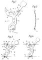
- a spacer including a body 10 mounted on a venetian blind slat 12 having a first edge 13 and a second edge 14.
- the body 10 is provided adjacent the first edge 13 with a first hook 16 bent downwardly, to project from one face of the body 10, as indicated in Figure 2.
- the body 10 includes a substantially rigid laterally extending body portion 18 provided with a second hook 20, similar to the hook 16 and also bent downwardly to project from the same face.
- a resilient arm 22 is also formed on the body 10 and is angled in the opposite direction and has, at its free edge, a third hook 24 of similar shape to the first and second hooks.
- a gap 26 is provided between the resilient arm 22 and the body portion 18, the arm 22 being capable of being flexed towards the second hook 20.
- an external handle 28 Forming an extension to the resilient arm 22 is an external handle 28. At the point where the external handle 28 meets the resilient arm 22, there are two points of weakness 30 for a reason to be explained later.
- the body 10 is provided with recess 32 for the passage of a lift cord of the venetian blind (if provided) and at the ends, the body is provided with recesses 34 for accommodating a rung of the ladder where it joins the upright side cords of the ladder.
- the spacer of the invention In operation, with a ladder type in place and having a ladder tape rung 36 extending across the slat, and upright cords 38 extending vertically, the spacer of the invention is positioned as shown in Figure 3 over the rung 36. In this orientation, the first hook 16 and the second hook 20 are located just outwardly of the edges 13 and 14 respectively, the distance between the hooks 16 and 20 being slightly greater than the width of the slat 12.
- the handle 28 is rotated anticlockwise and the first and second hooks 12 and 16 engage the edges 13 and 14 respectively.
- the handle 28 continues operation of the handle 28 in this manner causes the arm 22 to flex inwardly, so that the third hook 24 is moved towards the second hook 20 and can thus be engaged over the edge 14 to retain the spacer in place.
- the handle 20 can then be broken, twisted or cut off at the points of weakness 30.
- the recesses 34 are then located at the junction of the ladder tape rung 36 with the upright cords 38.
Landscapes
- Engineering & Computer Science (AREA)
- Structural Engineering (AREA)
- Architecture (AREA)
- Civil Engineering (AREA)
- Blinds (AREA)
- Materials For Medical Uses (AREA)
- Adhesive Tapes (AREA)
- Package Frames And Binding Bands (AREA)
Claims (10)
Priority Applications (1)
| Application Number | Priority Date | Filing Date | Title |
|---|---|---|---|
| AT89310717T ATE73891T1 (de) | 1988-11-04 | 1989-10-18 | Banddistanzstueck. |
Applications Claiming Priority (2)
| Application Number | Priority Date | Filing Date | Title |
|---|---|---|---|
| GB8825872A GB2224534B (en) | 1988-11-04 | 1988-11-04 | Tape spacer |
| GB8825872 | 1988-11-04 |
Publications (2)
| Publication Number | Publication Date |
|---|---|
| EP0367444A1 EP0367444A1 (de) | 1990-05-09 |
| EP0367444B1 true EP0367444B1 (de) | 1992-03-18 |
Family
ID=10646332
Family Applications (1)
| Application Number | Title | Priority Date | Filing Date |
|---|---|---|---|
| EP89310717A Expired - Lifetime EP0367444B1 (de) | 1988-11-04 | 1989-10-18 | Banddistanzstück |
Country Status (9)
| Country | Link |
|---|---|
| US (1) | US4974657A (de) |
| EP (1) | EP0367444B1 (de) |
| JP (1) | JPH02171489A (de) |
| AT (1) | ATE73891T1 (de) |
| DE (1) | DE68901025D1 (de) |
| ES (1) | ES2030273T3 (de) |
| GB (1) | GB2224534B (de) |
| IN (1) | IN176409B (de) |
| PT (1) | PT92173B (de) |
Families Citing this family (2)
| Publication number | Priority date | Publication date | Assignee | Title |
|---|---|---|---|---|
| DE4318805C1 (de) * | 1993-06-07 | 1994-06-23 | Warema Renkhoff Gmbh & Co Kg | Befestigungselement zur Fixierung der Lamelle einer Jalousie an einem Leiterband |
| US6833962B2 (en) * | 2000-12-04 | 2004-12-21 | Richard F. Bergen | Light altering device |
Family Cites Families (9)
| Publication number | Priority date | Publication date | Assignee | Title |
|---|---|---|---|---|
| DE1249499B (de) * | 1967-09-07 | |||
| CA476681A (en) * | 1951-09-04 | Calnetian Blinds | Venetian blinds | |
| NL77772C (de) * | 1900-01-01 | |||
| US2482036A (en) * | 1946-01-16 | 1949-09-13 | Kirsch Co | Venetian blind assembly and bottom rail therefor |
| CH263884A (de) * | 1946-10-19 | 1949-09-30 | Robert Jensen Otto | Stab für Jalousien. |
| US2647573A (en) * | 1951-06-04 | 1953-08-04 | Guarantee Specialty Mfg Co | Venetian blind tape retaining pin |
| US2678688A (en) * | 1951-10-19 | 1954-05-18 | Dragon George | Ladder tape of bead chain and the like |
| US2771946A (en) * | 1954-02-01 | 1956-11-27 | Sr John J Dixon | Replacement for venetian blind slatsupporting strap |
| US2877487A (en) * | 1957-07-08 | 1959-03-17 | Albert S Haislip | Stiffening brace for flexible venetian blind slats |
-
1988
- 1988-11-04 GB GB8825872A patent/GB2224534B/en not_active Expired - Fee Related
-
1989
- 1989-10-10 US US07/419,286 patent/US4974657A/en not_active Expired - Fee Related
- 1989-10-18 AT AT89310717T patent/ATE73891T1/de active
- 1989-10-18 ES ES198989310717T patent/ES2030273T3/es not_active Expired - Lifetime
- 1989-10-18 EP EP89310717A patent/EP0367444B1/de not_active Expired - Lifetime
- 1989-10-18 DE DE8989310717T patent/DE68901025D1/de not_active Expired - Fee Related
- 1989-10-19 IN IN963DE1989 patent/IN176409B/en unknown
- 1989-11-02 PT PT92173A patent/PT92173B/pt not_active IP Right Cessation
- 1989-11-02 JP JP1287256A patent/JPH02171489A/ja active Pending
Also Published As
| Publication number | Publication date |
|---|---|
| EP0367444A1 (de) | 1990-05-09 |
| JPH02171489A (ja) | 1990-07-03 |
| DE68901025D1 (de) | 1992-04-23 |
| ES2030273T3 (es) | 1992-10-16 |
| US4974657A (en) | 1990-12-04 |
| GB2224534A (en) | 1990-05-09 |
| PT92173B (pt) | 1995-08-09 |
| ATE73891T1 (de) | 1992-04-15 |
| GB8825872D0 (en) | 1988-12-07 |
| GB2224534B (en) | 1992-07-08 |
| IN176409B (de) | 1996-05-18 |
| PT92173A (pt) | 1990-05-31 |
Similar Documents
| Publication | Publication Date | Title |
|---|---|---|
| US4676292A (en) | Tilter apparatus for a slatted window covering | |
| EP0186715B1 (de) | Jalousie | |
| US5341865A (en) | Tilter mechanisms for a venetian blind | |
| US4245688A (en) | Cord lock for a venetian blind lift cord | |
| US4821789A (en) | Venetian blind with improved ladder tilt drum | |
| EP0075665B1 (de) | Farbbandkassette mit integrierter schwenkbar gelagerter Farbbandführung | |
| US4974657A (en) | Tape spacer | |
| US6321820B1 (en) | Slat positioning device for a venetian blind | |
| US5139073A (en) | Tape drum for a venetian blind tilt assembly | |
| US2662593A (en) | Venetian blind parts | |
| US7694470B2 (en) | Muntin clip | |
| US2678688A (en) | Ladder tape of bead chain and the like | |
| US2770296A (en) | Slat end guide for venetian blinds | |
| US4418461A (en) | Process for producing slats for a vertical slatted venetian blind | |
| US2576160A (en) | Venetian blind part | |
| US2661058A (en) | Venetian blind parts | |
| US3928937A (en) | Jalousie louver bracket | |
| JPH0737002Y2 (ja) | 索条係止具 | |
| JPH037518Y2 (de) | ||
| JPH04105396U (ja) | ブラインドのスラツト支持装置 | |
| US2528668A (en) | Film clip | |
| US2652114A (en) | Tape support for venetian blinds | |
| JPH11270254A (ja) | ブラインド | |
| EP0278230B1 (de) | Jalousie | |
| JPH056092U (ja) | ブラインドのラダーコード止め具 |
Legal Events
| Date | Code | Title | Description |
|---|---|---|---|
| PUAI | Public reference made under article 153(3) epc to a published international application that has entered the european phase |
Free format text: ORIGINAL CODE: 0009012 |
|
| AK | Designated contracting states |
Kind code of ref document: A1 Designated state(s): AT BE DE ES FR IT NL SE |
|
| 17P | Request for examination filed |
Effective date: 19900622 |
|
| 17Q | First examination report despatched |
Effective date: 19910307 |
|
| GRAA | (expected) grant |
Free format text: ORIGINAL CODE: 0009210 |
|
| AK | Designated contracting states |
Kind code of ref document: B1 Designated state(s): AT BE DE ES FR IT NL SE |
|
| REF | Corresponds to: |
Ref document number: 73891 Country of ref document: AT Date of ref document: 19920415 Kind code of ref document: T |
|
| REF | Corresponds to: |
Ref document number: 68901025 Country of ref document: DE Date of ref document: 19920423 |
|
| ET | Fr: translation filed | ||
| ITF | It: translation for a ep patent filed | ||
| REG | Reference to a national code |
Ref country code: ES Ref legal event code: FG2A Ref document number: 2030273 Country of ref document: ES Kind code of ref document: T3 |
|
| PLBE | No opposition filed within time limit |
Free format text: ORIGINAL CODE: 0009261 |
|
| STAA | Information on the status of an ep patent application or granted ep patent |
Free format text: STATUS: NO OPPOSITION FILED WITHIN TIME LIMIT |
|
| 26N | No opposition filed | ||
| PGFP | Annual fee paid to national office [announced via postgrant information from national office to epo] |
Ref country code: DE Payment date: 19931021 Year of fee payment: 5 |
|
| PGFP | Annual fee paid to national office [announced via postgrant information from national office to epo] |
Ref country code: FR Payment date: 19931026 Year of fee payment: 5 |
|
| PGFP | Annual fee paid to national office [announced via postgrant information from national office to epo] |
Ref country code: SE Payment date: 19931027 Year of fee payment: 5 |
|
| PGFP | Annual fee paid to national office [announced via postgrant information from national office to epo] |
Ref country code: ES Payment date: 19931029 Year of fee payment: 5 Ref country code: AT Payment date: 19931029 Year of fee payment: 5 |
|
| PGFP | Annual fee paid to national office [announced via postgrant information from national office to epo] |
Ref country code: NL Payment date: 19931031 Year of fee payment: 5 |
|
| PGFP | Annual fee paid to national office [announced via postgrant information from national office to epo] |
Ref country code: BE Payment date: 19931130 Year of fee payment: 5 |
|
| PG25 | Lapsed in a contracting state [announced via postgrant information from national office to epo] |
Ref country code: AT Effective date: 19941018 |
|
| PG25 | Lapsed in a contracting state [announced via postgrant information from national office to epo] |
Ref country code: SE Effective date: 19941019 Ref country code: ES Free format text: LAPSE BECAUSE OF EXPIRATION OF PROTECTION Effective date: 19941019 |
|
| PG25 | Lapsed in a contracting state [announced via postgrant information from national office to epo] |
Ref country code: BE Effective date: 19941031 |
|
| EAL | Se: european patent in force in sweden |
Ref document number: 89310717.7 |
|
| BERE | Be: lapsed |
Owner name: HUNTER DOUGLAS INDUSTRIES B.V. Effective date: 19941031 |
|
| PG25 | Lapsed in a contracting state [announced via postgrant information from national office to epo] |
Ref country code: NL Effective date: 19950501 |
|
| NLV4 | Nl: lapsed or anulled due to non-payment of the annual fee | ||
| PG25 | Lapsed in a contracting state [announced via postgrant information from national office to epo] |
Ref country code: FR Effective date: 19950630 |
|
| PG25 | Lapsed in a contracting state [announced via postgrant information from national office to epo] |
Ref country code: DE Effective date: 19950701 |
|
| EUG | Se: european patent has lapsed |
Ref document number: 89310717.7 |
|
| REG | Reference to a national code |
Ref country code: FR Ref legal event code: ST |
|
| REG | Reference to a national code |
Ref country code: ES Ref legal event code: FD2A Effective date: 19990601 |
|
| PG25 | Lapsed in a contracting state [announced via postgrant information from national office to epo] |
Ref country code: IT Free format text: LAPSE BECAUSE OF NON-PAYMENT OF DUE FEES;WARNING: LAPSES OF ITALIAN PATENTS WITH EFFECTIVE DATE BEFORE 2007 MAY HAVE OCCURRED AT ANY TIME BEFORE 2007. THE CORRECT EFFECTIVE DATE MAY BE DIFFERENT FROM THE ONE RECORDED. Effective date: 20051018 |