EP0367262A2 - Bride hydrauliquement fixable et outil rotatif - Google Patents
Bride hydrauliquement fixable et outil rotatif Download PDFInfo
- Publication number
- EP0367262A2 EP0367262A2 EP19890120300 EP89120300A EP0367262A2 EP 0367262 A2 EP0367262 A2 EP 0367262A2 EP 19890120300 EP19890120300 EP 19890120300 EP 89120300 A EP89120300 A EP 89120300A EP 0367262 A2 EP0367262 A2 EP 0367262A2
- Authority
- EP
- European Patent Office
- Prior art keywords
- flange
- chamber
- hydraulic
- piston
- oil
- Prior art date
- Legal status (The legal status is an assumption and is not a legal conclusion. Google has not performed a legal analysis and makes no representation as to the accuracy of the status listed.)
- Granted
Links
- 239000003921 oil Substances 0.000 claims abstract description 46
- 239000010720 hydraulic oil Substances 0.000 claims abstract description 11
- 230000008602 contraction Effects 0.000 claims abstract description 3
- 239000012530 fluid Substances 0.000 claims abstract 5
- 230000036316 preload Effects 0.000 claims description 17
- 230000001105 regulatory effect Effects 0.000 claims description 4
- 230000000694 effects Effects 0.000 description 4
- 238000009434 installation Methods 0.000 description 4
- 238000010586 diagram Methods 0.000 description 3
- 125000006850 spacer group Chemical group 0.000 description 3
- 238000003754 machining Methods 0.000 description 2
- 241001640034 Heteropterys Species 0.000 description 1
- 230000002411 adverse Effects 0.000 description 1
- 239000000463 material Substances 0.000 description 1
- 238000010008 shearing Methods 0.000 description 1
- 238000004904 shortening Methods 0.000 description 1
Images


Classifications
-
- F—MECHANICAL ENGINEERING; LIGHTING; HEATING; WEAPONS; BLASTING
- F16—ENGINEERING ELEMENTS AND UNITS; GENERAL MEASURES FOR PRODUCING AND MAINTAINING EFFECTIVE FUNCTIONING OF MACHINES OR INSTALLATIONS; THERMAL INSULATION IN GENERAL
- F16D—COUPLINGS FOR TRANSMITTING ROTATION; CLUTCHES; BRAKES
- F16D1/00—Couplings for rigidly connecting two coaxial shafts or other movable machine elements
- F16D1/06—Couplings for rigidly connecting two coaxial shafts or other movable machine elements for attachment of a member on a shaft or on a shaft-end
- F16D1/08—Couplings for rigidly connecting two coaxial shafts or other movable machine elements for attachment of a member on a shaft or on a shaft-end with clamping hub; with hub and longitudinal key
- F16D1/0805—Couplings for rigidly connecting two coaxial shafts or other movable machine elements for attachment of a member on a shaft or on a shaft-end with clamping hub; with hub and longitudinal key with radial clamping due to deformation of a resilient body or a body of fluid
-
- B—PERFORMING OPERATIONS; TRANSPORTING
- B23—MACHINE TOOLS; METAL-WORKING NOT OTHERWISE PROVIDED FOR
- B23B—TURNING; BORING
- B23B31/00—Chucks; Expansion mandrels; Adaptations thereof for remote control
- B23B31/02—Chucks
- B23B31/24—Chucks characterised by features relating primarily to remote control of the gripping means
- B23B31/30—Chucks characterised by features relating primarily to remote control of the gripping means using fluid-pressure means in the chuck
- B23B31/305—Chucks characterised by features relating primarily to remote control of the gripping means using fluid-pressure means in the chuck the gripping means is a deformable sleeve
-
- B—PERFORMING OPERATIONS; TRANSPORTING
- B23—MACHINE TOOLS; METAL-WORKING NOT OTHERWISE PROVIDED FOR
- B23P—METAL-WORKING NOT OTHERWISE PROVIDED FOR; COMBINED OPERATIONS; UNIVERSAL MACHINE TOOLS
- B23P11/00—Connecting or disconnecting metal parts or objects by metal-working techniques not otherwise provided for
-
- B—PERFORMING OPERATIONS; TRANSPORTING
- B26—HAND CUTTING TOOLS; CUTTING; SEVERING
- B26D—CUTTING; DETAILS COMMON TO MACHINES FOR PERFORATING, PUNCHING, CUTTING-OUT, STAMPING-OUT OR SEVERING
- B26D7/00—Details of apparatus for cutting, cutting-out, stamping-out, punching, perforating, or severing by means other than cutting
- B26D7/26—Means for mounting or adjusting the cutting member; Means for adjusting the stroke of the cutting member
- B26D7/2614—Means for mounting the cutting member
- B26D7/2621—Means for mounting the cutting member for circular cutters
-
- Y—GENERAL TAGGING OF NEW TECHNOLOGICAL DEVELOPMENTS; GENERAL TAGGING OF CROSS-SECTIONAL TECHNOLOGIES SPANNING OVER SEVERAL SECTIONS OF THE IPC; TECHNICAL SUBJECTS COVERED BY FORMER USPC CROSS-REFERENCE ART COLLECTIONS [XRACs] AND DIGESTS
- Y10—TECHNICAL SUBJECTS COVERED BY FORMER USPC
- Y10T—TECHNICAL SUBJECTS COVERED BY FORMER US CLASSIFICATION
- Y10T83/00—Cutting
- Y10T83/647—With means to convey work relative to tool station
- Y10T83/6584—Cut made parallel to direction of and during work movement
- Y10T83/6587—Including plural, laterally spaced tools
- Y10T83/6588—Tools mounted on common tool support
-
- Y—GENERAL TAGGING OF NEW TECHNOLOGICAL DEVELOPMENTS; GENERAL TAGGING OF CROSS-SECTIONAL TECHNOLOGIES SPANNING OVER SEVERAL SECTIONS OF THE IPC; TECHNICAL SUBJECTS COVERED BY FORMER USPC CROSS-REFERENCE ART COLLECTIONS [XRACs] AND DIGESTS
- Y10—TECHNICAL SUBJECTS COVERED BY FORMER USPC
- Y10T—TECHNICAL SUBJECTS COVERED BY FORMER US CLASSIFICATION
- Y10T83/00—Cutting
- Y10T83/768—Rotatable disc tool pair or tool and carrier
- Y10T83/7747—With means to permit replacement of tool
-
- Y—GENERAL TAGGING OF NEW TECHNOLOGICAL DEVELOPMENTS; GENERAL TAGGING OF CROSS-SECTIONAL TECHNOLOGIES SPANNING OVER SEVERAL SECTIONS OF THE IPC; TECHNICAL SUBJECTS COVERED BY FORMER USPC CROSS-REFERENCE ART COLLECTIONS [XRACs] AND DIGESTS
- Y10—TECHNICAL SUBJECTS COVERED BY FORMER USPC
- Y10T—TECHNICAL SUBJECTS COVERED BY FORMER US CLASSIFICATION
- Y10T83/00—Cutting
- Y10T83/768—Rotatable disc tool pair or tool and carrier
- Y10T83/7809—Tool pair comprises rotatable tools
- Y10T83/783—Tool pair comprises contacting overlapped discs
-
- Y—GENERAL TAGGING OF NEW TECHNOLOGICAL DEVELOPMENTS; GENERAL TAGGING OF CROSS-SECTIONAL TECHNOLOGIES SPANNING OVER SEVERAL SECTIONS OF THE IPC; TECHNICAL SUBJECTS COVERED BY FORMER USPC CROSS-REFERENCE ART COLLECTIONS [XRACs] AND DIGESTS
- Y10—TECHNICAL SUBJECTS COVERED BY FORMER USPC
- Y10T—TECHNICAL SUBJECTS COVERED BY FORMER US CLASSIFICATION
- Y10T83/00—Cutting
- Y10T83/929—Tool or tool with support
- Y10T83/9457—Joint or connection
- Y10T83/9461—Resiliently biased connection
-
- Y—GENERAL TAGGING OF NEW TECHNOLOGICAL DEVELOPMENTS; GENERAL TAGGING OF CROSS-SECTIONAL TECHNOLOGIES SPANNING OVER SEVERAL SECTIONS OF THE IPC; TECHNICAL SUBJECTS COVERED BY FORMER USPC CROSS-REFERENCE ART COLLECTIONS [XRACs] AND DIGESTS
- Y10—TECHNICAL SUBJECTS COVERED BY FORMER USPC
- Y10T—TECHNICAL SUBJECTS COVERED BY FORMER US CLASSIFICATION
- Y10T83/00—Cutting
- Y10T83/929—Tool or tool with support
- Y10T83/9457—Joint or connection
- Y10T83/9464—For rotary tool
- Y10T83/9466—Flexible sleevelike tool
Definitions
- This invention relates to a hydraulically fixable flange as well as to a rotary tool provided by a pair of upper and lower such devices with hydraulically fixable flanges, which are used when disc-shaped materials such as rotary knives, grinding wheels, gears, cutters and the like are fitted on the shaft, or when the shaft forming tools like end mills, drills, jigs, positioning devices and the like are fixed to the fitting holes.
- FIG. 1 Such art as shown in Fig. 1 is conventionally known as hydraulically fixable flange of this kind, wherein a ring-shaped tool 104 is fitted to one end of the periphery of the flange body 100 with a bolt 102, an annular hydraulic chamber 106 is formed within the said flange body 100, and a piston 112 having movable O-ring 110 is mounted in radial direction from the flange body 100 within the piston chamber 108 connected to this hydraulic chamber 106, and a set screw 118 is fastened at the center of a hollow cover 116 which is fixed to the flange body 100 with a bolt 114.
- the space with the shaft is larger or the fixing force is higher in the conventional hydraulically fixable flange.
- the number of pistons 106 is required to be increased, because the oil amount to be supplied to the hydraulic chamber 106 by the movement of the piston 112 becomes less, when the pressure in the hydraulic chamber 106 is caused to increase, or when the !5 width of the flange becomes wider. Consequently, there would be insufficient rigidity and strength of the flange body 100 which requires higher accuracy and a larger number of parts would be required, leading to economical disadvantages.
- Another drawback is that the volume of oil enclosed within the flange body 100 may change during the summer and the winter due to expansion of oil by heat, which weakens the clamping force and makes the fixing impossible, or it becomes hard to attach and detach because of the contraction of the bore in advance.
- the present invention provides a flange where a hydraulic chamber is provided within the flange body, and a hole for supplying hydraulic oil which is connected to the outside from the chamber is also provided, together with a valve system placed between the hydraulic chamber and the hole for supplying hydraulic oil so that the system can supply pressurized oil to the hydraulic chamber from the outside.
- the present invention provides a rotary tool arrangement where a hydraulic chamber is provided within a flange body, and a hole for supplying hydraulic oil, which is connected to the outside from the hydraulic chamber is also provided, together with a valve system placed between the said hydraulic chamber and the hole for supplying hydraulic oil so that the system can supply pressurized oil to the said hydraulic chamber from the outside, and a ring-shaped tool is mounted on the outer periphery of the said flange body which is fitted on the outer periphery of the shaft, said ring-shaped tool being fixed on said shaft by contracting the bore of the inner circumference of the said flange body by feed1ng pressurized oil to the hydraulic chamber formed within the said flange.
- a multiple of ring-shaped tools can be mounted on the outer periphery of the said flange body at prescribed intervals in axial direction of the said shaft.
- a movable piston regulating the hydraulic oil of the chamber and an elastic body is provided to this piston so that it may energize it onto the side of the hydraulic chamber.
- the piston regulating the hydraulic oil of the chamber is made movable within the prescribed range in this hydraulic chamber, and an elastic body is supplied to this piston so that it can energize the piston onto the side of the hydraulic chamber.
- a preload monitor is provided to the piston so that it can freely come out to the flange body and then can retract.
- pressurized oil is supplied to the hydraulic chamber through the hole for supplying hydraulic oil from outside by means of the valve system when the pressure within the hydraulic chamber is lower, while pressurized oil is discharged outside by means of the valve system when the pressure in the hydraulic chamber is released.
- the piston left free to move about within the prescribed range is pressed to the side of the hydraulic chamber by means of an elastic body, the pressure therein will be at the preset level as if no elastic body were set, and if the prescribed pressure is exceeded, the elastic body will get active and try to reduce whatever change might occur in the hydraulic pressure.
- the pressure in the hydraulic chamber can easily be known by transmitting the movement of the piston to the outside by way of a preload monitor.
- two or more ring-shaped tools are attached to the outer periphery of the flange body to let them offset each other's shearing force to which they are exposed. This reduces the force of thrust working between the flange body and the shaft and makes it possible to cut a thick Plate.
- ring-shaped tools are arranged at smaller intervals for narrower cutting, it is possible to lengthen the width of the flange and widen the hydraulic chamber without shortening the flange width as before.
- FIG. 10 refers to a loop-shaped flange body.
- Ring-shaped tool 14 is fastened with bolts 12 to one edge of the periphery of this flange body 10.
- Circuiar hydraulic chamber 16 is formed within the above flange body 10. Formed in the space between the above hydraulic chamber 16 and the periphery of the flange body 10 are a communicating hole 18 and fitting hole 22 into which to install external hydraulic pressure supply unit.
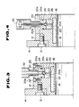
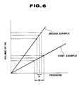
- Fig. 5 shows the second example of application of this invention.
- the same reference numerals are attached to them, with the explanation omitted.
- the communicating hole 18 and the fitting hole 22 to install external hydraulic pressure supply unit 20 are formed between the above hydraulic pressure chamber 16 and the periphery of the flange body 10.
- the piston chamber 38 is linked up to the above hydraulic pressure chamber 16 and this piston chamber 38 is sealed up by cover 40a fixed with the fastening bolt 42. Inside the above piston chamber 38 piston 44 is arranged to slide freely to and from the hydraulic pressure chamber 16, and there is also the spring 46 to give additional force to throw this piston 44 to the side of hydraulic pressure chamber 16.
- Numeral 48 on Fig. 5 refers to O-ring.
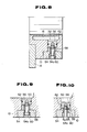
- Fig. 7 through Fig. 10 illustrate the third example 1f application of this invention.
- the same numerals are assigned to those parts shown on Fig. 2 as in the first and second examples, and therefore the explanation is omitted here.
- piston chamber 50 is linked up with the above hydraulic pressure chamber 16.
- the external opening of this piston chamber 50 is fitted with cover 54 fixed by fastening bolt 52.
- piston 56 set to freely slide toward and away from the hydraulic pressure chamber 16.
- spring 58 attached to push this piston 56 toward the side of the hydraulic pressure chamber 16.
- Preload setting bolt 60 is screwed into the above piston 56 while passing through the above preload setting bolt 60 is arranged to freely pop up or down into the fixing depression on the above cover 54.
- Numeral 62 on Fig. 1 refers to O-ring.
- the situation is as if there were no spring 58 set until the piston 56 in the piston chamber 50 begins moving against the energy provided by the spring 58 (See Fig. 9), and, as shown in Fig. 11. the pressure rises as described in Fig. 2. Then, when the pressure in the hydraulic pressure chamber rises above the prescribed level, the piston 56 in the piston chamber 50 begins moving against the additional force emanating from the spring 58. Accordingly the head of the preload setting bolt 60 moves outwards within the fixture depression 54a of the cover 54 (see Fig. 8) and protrudes outside (see Fig. 10). Consequently, the pressure within the hydraulic pressure chamber 16 can easily be known by checking the position of the head of the above preload setting bolt 60 from outside.
- preloaded spring 58 (elastic body) is built-in in this third example of application, the same behavior can be noted as in the absence of an elastic body until the pressure reaches the point equivalent to the preload. Where the pressure exceeds the level comparable to the preload, the elastic body gets into action, causing the necessary amount of oil to increase a little compared with the first example of application shown on Fig. 2. The same effect as in the presence of an elastic body will be produced on the change of hydraulic pressure. Since the position of preload setting bolt 60 indicates the level of pressure within the hydraulic pressure chamber 16, it is possible to monitor the fastening power at work from outside.
- the head of the preload setting bolt 60 comes into contact with installation depression 54a of the cover 54 (See Fig. 9) to apply a preload upon the piston 56 not to move farther toward the hydraulic pressure chamber 16. It is also alright to fit a stopper at a place of piston chamber 50 near the hydraulic pressure chamber 16 and put the piston 56 onto this stopper in order to prevent the piston 56 from moving nearer to the hydraulic pressure chamber 16.
- FIG. 12 and Fig. 13 Shown on Fig. 12 and Fig. 13 are the fourth example of application of this invention.
- This fourth example uses a hydraulically fixable flange as described in the first example.
- the rotary knife in the fourth case is composed of two pieces of ring-shaped tool 64 fitted to the flange body.
- the installation bolt 66 is used to fix the two tools 64.
- a ring-like spacer 68 is placed between the two tools 64. The presence of this spacer 68 keeps the two tools 64 fitted along the direction of the axis of the shaft 70 at a certain interval.
- This pair of rotary knives are used to cut sheet-like workpiece S as shown in Fig. 13.
- FIG. 15 is the fifth example of application of this invention.
- This diagram shows an example of the flange body 10 fitted with four ring-shaped tools 64.
- Three ringshaped spacers 68 determine intervals among the four ring-shaped tools 64 arranged in the direction of the axis of the shaft 70.
- the nuts 72 are used to fasten the ring-shaped tools 64.
- any desired number of ring-shaped tools 64 can be fitted to the flange body 10 and they can be lined at intervals of whatever distance is desired.
- the first embodiment of this invention explains a hydraulic pressure chamber within the flange body, and a hydraulic pressure supply porthole runs through the chamber to the outside.
- a valve mechanism that is installed between the above hydraulic pressure chamber and the hydraulic pressure supply hole, which makes it possible to feed pressure oil into the chamber from outside. Since both the supply of pressure oil into the chamber and the release of pressure from there become smooth with the opening and closing operation of the valve mechanism, it is possible to design smaller individual parts to the necessary minimum size (smaller parts can withstand all the more greater pressure) without any worry about oil quantity within the hydraulic pressure chamber. Consequently it becomes possible to reduce the machining of the flange body to the necessary minimum level, which will adversely affect its strength, precision and rigidity and it is also possible to make a flexible response to the need for larger units.
- the second embodiment of this invention shows the arrangement of the piston to regulate the hydraulic pressure in the hydraulic pressure chamber and freely move about there and an elastic body to thrust the piston to the side of the above hydraulic pressure chamber. Even in the case of a change in the quantity of oil due to temperature change, oil volume fluctuations or oil leakage, it is possible to reduce the likely change in the pressure within the hydraulic pressure chamber by moving the piston by means of the elastic body and consequently retain stable fastening force.
- the pistons are arranged to regulate the hydraulic pressure in the hydraulic pressure chamber and move freely within the prescribed bounds and an elastic body is installed to thrust the piston to the side of the above hydraulic pressure chamber.
- the pressure With the above described piston pressed toward the hydraulic pressure chamber by the elastic body, the pressure With1n the hydraulic pressure chamber finds itself in a situation similar to one created with no elastic body set up. If the pressure exceeds the preset level, the elastic body begins functioning, minimizing the pressure change even in the case of a fluctuation of oil quantity due to temperature-caused oil volume changes or oil leakage. It is also possible to retain stable fastening force with a least amount of oil needed and to take a quick and smooth disconnecting action.
- the second variation of the first embodiment of this invention provides the preload monitor to the piston and arranges it to freely pop up into the flange body.
- the preload monitor indicates the transfer of the piston and enables the operator to readily know the pressure in the hydraulic pressure chamber and safely confirm the fastening force.
- the rotary knives in the second embodiment of the invention are fixed to the shaft when the internal boundary of the flange body is shortened by supplying pressure oil into the hydraulic pressure chamber formed within the above flange body.
- a hydraulic pressure supply hole is run through the hydraulic pressure chamber to reach the outside with a valve mechanism placed between the chamber and the hole to enable the pressure oil to be fed into the chamber from outside.
- Ring-shaped tools are lined up along the periphery of the flange body at certain intervals in the direction of the axis of the shaft. The cutting force which one tool is exposed to is offset by that of another, which reduces the force of thrust at play between the flange body and the shaft and makes it possible to cut a thick plate.
- the ring-shaped tools are arranged at smaller intervals in order to cut narrow pieces, it is possible to enlarge the width of the flange body and create a greater pressure oil chamber.
Landscapes
- Engineering & Computer Science (AREA)
- Mechanical Engineering (AREA)
- General Engineering & Computer Science (AREA)
- Life Sciences & Earth Sciences (AREA)
- Forests & Forestry (AREA)
- Physics & Mathematics (AREA)
- Fluid Mechanics (AREA)
- Clamps And Clips (AREA)
- Gripping On Spindles (AREA)
- Joints Allowing Movement (AREA)
Applications Claiming Priority (8)
| Application Number | Priority Date | Filing Date | Title |
|---|---|---|---|
| JP143318/88 | 1988-11-01 | ||
| JP63277001A JPH02124203A (ja) | 1988-11-01 | 1988-11-01 | 油圧固定フランジ |
| JP277001/88 | 1988-11-01 | ||
| JP143319/88 | 1988-11-01 | ||
| JP1988143319U JPH0263906U (fr) | 1988-11-01 | 1988-11-01 | |
| JP1988143318U JPH0751202Y2 (ja) | 1988-11-01 | 1988-11-01 | 油圧固定フランジの着脱機構 |
| JP1989054765U JPH02145994U (fr) | 1989-05-12 | 1989-05-12 | |
| JP54765/89 | 1989-05-12 |
Publications (3)
| Publication Number | Publication Date |
|---|---|
| EP0367262A2 true EP0367262A2 (fr) | 1990-05-09 |
| EP0367262A3 EP0367262A3 (fr) | 1991-08-07 |
| EP0367262B1 EP0367262B1 (fr) | 1994-11-02 |
Family
ID=27463105
Family Applications (1)
| Application Number | Title | Priority Date | Filing Date |
|---|---|---|---|
| EP19890120300 Expired - Lifetime EP0367262B1 (fr) | 1988-11-01 | 1989-11-02 | Bride hydrauliquement fixable et outil rotatif |
Country Status (3)
| Country | Link |
|---|---|
| US (1) | US5099733A (fr) |
| EP (1) | EP0367262B1 (fr) |
| DE (1) | DE68919185T2 (fr) |
Cited By (2)
| Publication number | Priority date | Publication date | Assignee | Title |
|---|---|---|---|---|
| WO1999056901A1 (fr) * | 1998-05-07 | 1999-11-11 | Renishaw Plc | Dispositif de changement d'outils |
| CN111120490A (zh) * | 2019-12-13 | 2020-05-08 | 扬力集团股份有限公司 | 一种压力机组合机身用液压预紧螺母 |
Families Citing this family (5)
| Publication number | Priority date | Publication date | Assignee | Title |
|---|---|---|---|---|
| FI111094B (fi) | 1997-10-24 | 2003-05-30 | Suokone Oy | Kytkin |
| US6325127B1 (en) * | 1999-01-12 | 2001-12-04 | Kappler Protective Apparel & Fabrics | Ultrasonic sewing machine and bonding wheel assembly |
| US20090151534A1 (en) * | 2007-11-09 | 2009-06-18 | Rooke C Aldon | Slitter Line Knife Holder Assembly |
| DE102012023431B4 (de) * | 2012-11-30 | 2023-11-16 | Claas Saulgau Gmbh | Messerträger für eine Häckseltrommel und Häckseltrommel für einen Feldhäcksler |
| CA2979761A1 (fr) * | 2015-04-04 | 2016-10-13 | Esm Energie- Und Schwingungstechnik Mitsch Gmbh | Raccordement reversible de composants mecaniques |
Citations (5)
| Publication number | Priority date | Publication date | Assignee | Title |
|---|---|---|---|---|
| FR2008624A1 (fr) * | 1968-05-16 | 1970-01-23 | Balas Collet Co | |
| FR2180235A5 (fr) * | 1972-04-14 | 1973-11-23 | Guillon Robert | |
| GB2033285A (en) * | 1978-10-13 | 1980-05-21 | Rochette Cenpa | Mounting block for rotary cutter |
| GB2111172A (en) * | 1981-12-09 | 1983-06-29 | Hurth Verwaltungs Gmbh | Frictional releasable shaft-hub connexion |
| JPS59129612A (ja) * | 1983-01-11 | 1984-07-26 | Mitsubishi Metal Corp | 廻転加工工具 |
Family Cites Families (2)
| Publication number | Priority date | Publication date | Assignee | Title |
|---|---|---|---|---|
| US4220064A (en) * | 1979-02-21 | 1980-09-02 | Paxson Machine Company | Clamping device |
| IT1157278B (it) * | 1981-06-05 | 1987-02-11 | Hauni Werke Koerber & Co Kg | Dispositivo di taglio |
-
1989
- 1989-11-01 US US07/429,932 patent/US5099733A/en not_active Expired - Lifetime
- 1989-11-02 EP EP19890120300 patent/EP0367262B1/fr not_active Expired - Lifetime
- 1989-11-02 DE DE68919185T patent/DE68919185T2/de not_active Expired - Lifetime
Patent Citations (5)
| Publication number | Priority date | Publication date | Assignee | Title |
|---|---|---|---|---|
| FR2008624A1 (fr) * | 1968-05-16 | 1970-01-23 | Balas Collet Co | |
| FR2180235A5 (fr) * | 1972-04-14 | 1973-11-23 | Guillon Robert | |
| GB2033285A (en) * | 1978-10-13 | 1980-05-21 | Rochette Cenpa | Mounting block for rotary cutter |
| GB2111172A (en) * | 1981-12-09 | 1983-06-29 | Hurth Verwaltungs Gmbh | Frictional releasable shaft-hub connexion |
| JPS59129612A (ja) * | 1983-01-11 | 1984-07-26 | Mitsubishi Metal Corp | 廻転加工工具 |
Non-Patent Citations (1)
| Title |
|---|
| PATENT ABSTRACTS OF JAPAN vol. 8, no. 258 (M-340)(1695) 27 November 1984, & JP-A-59 129612 (MITSUBISHI KINZOKU K.K.) 26 July 1984, * |
Cited By (2)
| Publication number | Priority date | Publication date | Assignee | Title |
|---|---|---|---|---|
| WO1999056901A1 (fr) * | 1998-05-07 | 1999-11-11 | Renishaw Plc | Dispositif de changement d'outils |
| CN111120490A (zh) * | 2019-12-13 | 2020-05-08 | 扬力集团股份有限公司 | 一种压力机组合机身用液压预紧螺母 |
Also Published As
| Publication number | Publication date |
|---|---|
| DE68919185D1 (de) | 1994-12-08 |
| US5099733A (en) | 1992-03-31 |
| EP0367262A3 (fr) | 1991-08-07 |
| DE68919185T2 (de) | 1995-04-20 |
| EP0367262B1 (fr) | 1994-11-02 |
Similar Documents
| Publication | Publication Date | Title |
|---|---|---|
| KR930003339B1 (ko) | 스핀들 록 업 장치 | |
| US4068559A (en) | Tool fastening device | |
| CN107921549B (zh) | 具有冷却剂供应的金属切削刀具 | |
| US5099733A (en) | Rotary knife | |
| US3753624A (en) | Boring tool for small diameters | |
| US3945302A (en) | Diaphragm adjustment tool | |
| JPS61230867A (ja) | 砥石車用締付装置 | |
| US6658987B1 (en) | Sealing device for a piston which is subjected to the action of a pressure medium and which is arranged in a working cylinder | |
| US4697966A (en) | Pressurized clamp for securing tools or workpieces | |
| US4094521A (en) | Collet chuck | |
| US5048388A (en) | Rotary knife assembly | |
| US4648784A (en) | Drive protection device connectable between two portions of a driven operating device | |
| JP2718500B2 (ja) | 液圧式衝撃トルク発生装置 | |
| EP0164549B1 (fr) | Dispositif pour porte-outil | |
| US5435577A (en) | Hydraulic clamping device | |
| EP0078116B1 (fr) | Embrayage à deux disques de friction | |
| US2833169A (en) | Coupling structure | |
| KR102536273B1 (ko) | 절삭 공구 | |
| KR102578108B1 (ko) | 절삭 공구 및 조절 장치가 장착된 절삭 공구를 위한 조절 장치 | |
| US4781095A (en) | Pusher | |
| JPS6350123B2 (fr) | ||
| CA1298067C (fr) | Dispositif d'assemblage et d'exploitation avec bride d'autoserrage | |
| CN218747554U (zh) | 用于液压工具的冲压组件和液压工具 | |
| US3259394A (en) | Radially adjustable chuck | |
| KR940005308B1 (ko) | 유압고정 후랜지 |
Legal Events
| Date | Code | Title | Description |
|---|---|---|---|
| PUAI | Public reference made under article 153(3) epc to a published international application that has entered the european phase |
Free format text: ORIGINAL CODE: 0009012 |
|
| AK | Designated contracting states |
Kind code of ref document: A2 Designated state(s): DE FR GB IT |
|
| 17P | Request for examination filed |
Effective date: 19900419 |
|
| PUAL | Search report despatched |
Free format text: ORIGINAL CODE: 0009013 |
|
| AK | Designated contracting states |
Kind code of ref document: A3 Designated state(s): DE FR GB IT |
|
| RAP1 | Party data changed (applicant data changed or rights of an application transferred) |
Owner name: MITSUBISHI MATERIALS CORPORATION |
|
| 17Q | First examination report despatched |
Effective date: 19921104 |
|
| GRAA | (expected) grant |
Free format text: ORIGINAL CODE: 0009210 |
|
| AK | Designated contracting states |
Kind code of ref document: B1 Designated state(s): DE FR GB IT |
|
| REF | Corresponds to: |
Ref document number: 68919185 Country of ref document: DE Date of ref document: 19941208 |
|
| ET | Fr: translation filed | ||
| ITF | It: translation for a ep patent filed | ||
| PLBE | No opposition filed within time limit |
Free format text: ORIGINAL CODE: 0009261 |
|
| STAA | Information on the status of an ep patent application or granted ep patent |
Free format text: STATUS: NO OPPOSITION FILED WITHIN TIME LIMIT |
|
| 26N | No opposition filed | ||
| PGFP | Annual fee paid to national office [announced via postgrant information from national office to epo] |
Ref country code: GB Payment date: 19961031 Year of fee payment: 8 |
|
| PGFP | Annual fee paid to national office [announced via postgrant information from national office to epo] |
Ref country code: FR Payment date: 19961108 Year of fee payment: 8 |
|
| PG25 | Lapsed in a contracting state [announced via postgrant information from national office to epo] |
Ref country code: GB Free format text: LAPSE BECAUSE OF NON-PAYMENT OF DUE FEES Effective date: 19971102 |
|
| PG25 | Lapsed in a contracting state [announced via postgrant information from national office to epo] |
Ref country code: FR Free format text: THE PATENT HAS BEEN ANNULLED BY A DECISION OF A NATIONAL AUTHORITY Effective date: 19971130 |
|
| GBPC | Gb: european patent ceased through non-payment of renewal fee |
Effective date: 19971102 |
|
| REG | Reference to a national code |
Ref country code: FR Ref legal event code: ST |
|
| PG25 | Lapsed in a contracting state [announced via postgrant information from national office to epo] |
Ref country code: IT Free format text: LAPSE BECAUSE OF NON-PAYMENT OF DUE FEES;WARNING: LAPSES OF ITALIAN PATENTS WITH EFFECTIVE DATE BEFORE 2007 MAY HAVE OCCURRED AT ANY TIME BEFORE 2007. THE CORRECT EFFECTIVE DATE MAY BE DIFFERENT FROM THE ONE RECORDED. Effective date: 20051102 |
|
| PGFP | Annual fee paid to national office [announced via postgrant information from national office to epo] |
Ref country code: DE Payment date: 20081121 Year of fee payment: 20 |