EP0366877A1 - Vorrichtung zum Herstellen von faserigen Nahrungsprodukten - Google Patents
Vorrichtung zum Herstellen von faserigen Nahrungsprodukten Download PDFInfo
- Publication number
- EP0366877A1 EP0366877A1 EP89113904A EP89113904A EP0366877A1 EP 0366877 A1 EP0366877 A1 EP 0366877A1 EP 89113904 A EP89113904 A EP 89113904A EP 89113904 A EP89113904 A EP 89113904A EP 0366877 A1 EP0366877 A1 EP 0366877A1
- Authority
- EP
- European Patent Office
- Prior art keywords
- fill
- rim
- food
- mold
- mold cavity
- Prior art date
- Legal status (The legal status is an assumption and is not a legal conclusion. Google has not performed a legal analysis and makes no representation as to the accuracy of the status listed.)
- Granted
Links
Images


Classifications
-
- A—HUMAN NECESSITIES
- A22—BUTCHERING; MEAT TREATMENT; PROCESSING POULTRY OR FISH
- A22C—PROCESSING MEAT, POULTRY, OR FISH
- A22C7/00—Apparatus for pounding, forming, or pressing meat, sausage-meat, or meat products
Definitions
- any of those machines, and others as well, are capable of producing food patties of consistent size, weight, and configuration on a high volume basis, substantial problems may be encountered when the machines are required to mold patties from food products which, unlike hamburger, have not been ground to relatively small particle size.
- the starting material may consist of whole poultry breasts, large segments of pork or other meat, large fish fillets, or relatively large pieces of almost any food product that has an appreciable fiber content.
- food products of this general kind are referred to as "fibrous food products”.
- a molding mechanism that solves many of the problems encountered in molding food patties from a whole fiber food product is described in Sandberg et al U.S. Patent No. 4,356,595 issued November 2, 1982.
- the food product is pumped into the mold cavities through aligned fill apertures in the fill member; the fill apertures are preferably matched in size to the mold cavities they serve.
- the molding mechanism presents some technical problems in its operation when employed to mold patties from fibrous food products.
- the total clearance between the mold plate and the adjacent cover member and fill member is only about 0.001 inch to 0.003 inch (0.025 cm. to 0.076 cm.).
- the pumping pressures may be 400 psi (28 Kg/sq.cm.) in the machine of the Richards patent, 220 psi (15.5 Kg/sq.cm.) in the mechanism of the Lamartino patent, and 250 psi (17.6 Kg/sq.cm.) in the Sandberg et al Patent No. 4,054,967.
- Another object of the invention is to provide a new and improved food patty molding mechanism, adapted to use with fibrous food products, that precludes cutting fibers in the food product as it is pumped into the mold cavities, yet effectively shears off any food product along the surface of the mold cavity facing the fill member.
- a further object of the invention is to provide a new and improved molding mechanism for use with fibrous food products that minimizes production of "breather fines”.
- the invention relates to a molding mechanism for molding food patties from a fibrous food product, which molding mechanism comprises fill directing means including a fill member having a first planar surface with at least one fill port extending through the fill member and the first planar surface, cover means including a cover member having a second planar surface in parallel spaced relation to the first planar surface, and a mold plate having opposed planar surfaces, positioned in close fitting relation between the first and second planar surfaces, the mold plate having at least one mold cavity of predetermined configuration and area therethrough; the area of the mold cavity is substantially larger than the area of the fill port at the first planar surface.
- Mold plate drive means are provided for driving the mold plate, cyclically, from a fill position in which the mold cavity is aligned with the fill port to a discharge position in which the mold cavity is displaced beyond the fill member, and for subsequently driving the mold plate to its fill position.
- the fill directing means includes a transitional rim for the fill port, adjacent the first planar surface, past which the food product flows into the mold cavity with an appreciable change of direction, the transitional rim having a rounded curvature that precludes appreciable damage to fibers in the food product; the fill directing means further includes a cutting rim for the fill port, at the first planar surface, past which at least a part of the mold cavity moves when the mold plate is driven toward its discharge position, the cutting rim having a sharp edge for shearing food product from the food patty along a plane coincident with the first planar surface.
- Figs. 1 and 2 illustrate a food patty molding mechanism 10 for molding food patties from a fibrous food product.
- Molding mechanism 10 is of the kind described and illustrated in greater detail in the aforementioned Richards U.S. Patent No. Re. 30,096 and includes some of the improved features disclosed in the aforementioned Sandberg et al U.S. Patent No. 4,697,308. The disclosures of those two prior United States patents are incorporated in this specification by reference, and familiarity with them is assumed.
- Molding mechanism 10, Fig. 1 usually includes two food pumps, but only the outlet chamber 12 of one pump is shown; the two pumps operate in alternation to afford a continuous pumping action.
- a fibrous food product is pumped through a slot 13 into a pump manifold 14.
- Pump manifold 14 includes a valve cylinder 16 fitted into an opening 17 immediately beyond the pump chamber wall 18 that defines slot 13.
- Valve cylinder 16 includes two intake slots; only one of these intake slots 19 is illustrated. Intake slot 19 is alignable with the outlet slot 13 for pump chamber 12. Rotation of valve cylinder 16 is effective to move its intake slot 19 out of alignment with pump outlet slot 13 when the food pump feeding chamber 12 is not in operation.
- Valve cylinder 16 also includes an elongated outlet slot 21 aligned with a fill passage 22 in manifold 14.
- the upper part of manifold 14 is covered by a fill plate 23 that includes a fill plate insert 24.
- Fill plate 23 and insert 24 are referred to conjointly herein as the "fill member" of mechanism 10.
- the fill plate insert 24 is keyed into fill plate 23 for accurate location; insert 24 extends across the full operating width of molding mechanism 10 and includes a plurality of fill ports 26; see Figs. 1 and 2.
- Figs. 1 and 2 In the illustrated molding mechanism 10, which is set up for molding relatively long, narrow food patties, there are a total of twenty fill ports 26, but only a few of the fill ports are shown in Fig. 2.
- the entrance rim of each fill port 26, facing passage 22, is rounded as indicated at 27 in Fig. 1.
- a mold plate 28 is slidably supported upon a planar upper surface 30 of the fill member comprising fill plate 23 and fill plate insert 24, as shown in Fig. 1. Mold plate 28 is cyclically slidably movable from the fill position shown at the left side of Fig. 1 to a discharge or knockout position shown in part at 28A.
- the mold plate drive means is not shown in the drawings; appropriate mold plate drives are well known in the art.
- Mold plate 28 includes a plurality of mold cavities 29 that are aligned one-for-one with fill apertures 26. The discharge positions for two of the mold cavities are shown at 29A in Fig. 1. As is apparent from Figs. 1 and 2, the area of each mold cavity is substantially larger than the area of its associated fill port at the planar top surface 30 of fill member 23,24.
- a series of knockout cups 31 are included in molding mechanism 10, one knockout cupt 31 for each mold cavity 29. Whenever mold plate 28 is in its discharge position 28A, each of its mold cavities is in a position 29A aligned with one of the knockout cups 31. Knockout cups 31 conform closely in size and configuration to the mold cavities with which they are associated. A takeaway conveyor 32 is positioned below mold plate 28 to receive molded food patties dislodged from the mold cavities by knockout cups 31.
- a breather plate 33 is positioned immediately above mold plate 28 in molding mechanism 10.
- Plate 33 is provided with a plurality of air pressure release passages 34.
- a plurality of tiny breather holes 60 connect each passage 34 with the lower surface 40 of breather plate 33.
- a cover plate 35 positioned above breather plate 33 closes off the top surfaces of breather passages 34. Plates 33 and 35 are referred to conjointly herein as the "cover member" of molding mechanism 10.
- molding mechanism 10 is well known in the art from the aforementioned United States patents to Richards and Sandberg and from the FORMAX 26 patty molding machines manufactured and sold by Formax, Inc. of Mokena, Illinois, U.S.A.
- a supply of a moldable food product is pumped under pressure from chamber 12 through valve slots 19 and 21 and into fill passage 22.
- the food product under relatively high pressure, also fills each of the fill ports 26 in fill plate insert 24.
- mold plate 28 With mold plate 28 in the fill position shown at the left side of Fig. 1, the food product is forced under pressure through passage 22 and ports 26, filling each of the mold cavities 29. After the mold cavities have been filled, mold plate 28 is advanced to its discharge position, with the mold cavities in locations 28A. Knockout cups 31 are then driven downwardly, discharging the molded food patties 30 from the mold cavities, at positions 29A, onto takeaway conveyor 32. The knockout cups are then retracted and mold plate 28 is moved back to its fill position to receive a new charge of food product in each of its mold cavities 29. This cycle of operation is continued indefinitely; the cycle rate for mold plate 28 may be as high as eighty or ninety cycles per minute. As long as molding mechanism 10 is in operation, the food product is maintained under constant or intermittent high pressure in pump chamber 12 (or in the second pump), valve cylinder 16, fill passage 22, and fill apertures 26.
- the total of the clearances at the surfaces 30 and 40 below and above mold plate 28 is quite small, usually about 0.001 to 0.003 inch (0.025 cm. to 0.076 cm.)
- mold plate 28 moves its discharge position the presssure of the food product forces the mold plate up against cover member 33 so that essentially all of this clearance appears along planar surface 30.
- substantial difficulties may be encountered, due to food product fibers trailing from mold cavities 29 between mold plate 28 and fill member 23,24; these include poor registration of patties on conveyor 32 and appearance defects.
- shear blades 45 In molding mechanism 10, this difficulty is effectively eliminated by use of a series of shear blades 45, Fig. 1, one shear blade 45 for each mold cavity 29.
- a guide bar 47 holds blades 45 in place.
- Each shear blade 45 has a width exceeding the maximum width of its associated mold cavity 29.
- Shear blades 45 are aligned one-for-one with pusher rods 51.
- a series of pistons 53 in a manifold 55 are aligned one-for-one with pusher rods 51.
- shear blades 45 are at or very slightly displaced below the level of the planar surface 30 so that the shear blades do not interfere with movement of mold plate 28 to its discharge position.
- pistons 53 are actuated. Upward movement of each piston 53 drives its pusher rod 51 upwardly and forces one shear blade 45 up into firm engagement with the bottom surface of mold plate 28 as the mold plate is emerging from molding mechanism 10. The pressure of engagement between each shear blade 45 and the bottom of mold plate 28 may be substantial. Actuation of pistons 53 ends shortly before the mold plate reaches its discharge positions 28A. As a consequence, shear bars 45 drop back down from surface 30 through a very limited distance, which should preferably be less than 0.05 inch (0.127 cm.).
- shear bars 45 make it practical to utilize molding mechanism 10 with fibrous food products at substantially higher temperatures, and consequently lower filling pressures, than would be permissible in the same mechanism not equipped with the shear bar apparatus, with a resultant substantial saving for the machine operator.
- the shear mechanism comprising blade 45 has been shown only to disclose the best mode for the invention and may be omitted.
- each mold cavity 29 has an area substantially larger than the area of its associated food port 26 at surface 30; this relationship is clearly apparent in both Figs. 1 and 2.
- food product entering cavities 29 from ports 26 undergoes an appreciable change of direction as it traverses the front transitional rim 41 of each food port, as shown by arrows A in Fig. 1.
- rim 41 were a sharp cutting edge substantial damage to the food product fibers could occur, with consequent deterioration in the appearance, texture, and general quality of the food patties.
- transitional rims 41 on food ports 26 should be smooth and rounded to facilitate passage of the food product with the required substantial and rather abrupt change of direction (arrows A) while avoiding damage to fibers in the food product.
- each fill/shear bar 42 is shifted a short distance longitudinally to bring another segment 43 of the bar into alignment with the front of each fill port 26. This condition is illustrated in Fig.
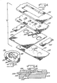
- Fig. 3 illustrates a patty molding mechanism 110 comprising a further embodiment of the present invention; individual components and details of construction are shown in Figs. 4 and 5.
- Molding mechanism 110 is derived from the food patty molding machine of Sandberg et al U.S. Patent No. 4,054,967; familiarity with that machine and with the commercial FORMAX F-19 machine, manufactured and sold in substantial quantities by Formax, Inc. of Mokena, Illinois, are assumed.
- Molding mechanism 110 comprises a pump housing including two housing members 101 and 102.
- An inlet opening 103 in housing member 102 communicates with a pump chamber in which a pump plunger 104 is positioned.
- the lower end of the pump chamber comprises a fill passage 122 through a pump base 114.
- Fill passage 122 serves four fill ports 126 that extend through a fill plate 123.
- the upper rims of fill ports 126, facing fill passage 122, are all smooothly rounded to avoid cutting or tearing of fibrous food products processed in molding mechanism 110.
- the rims of food ports 126 facing downwardly away from fill passage 122 are of different construction.
- the lower rim of each fill port 126, facing a mold plate 128, includes a rounded, smooth, transitional rim portion 141 around approximately one-half of the fill port.
- the remaining rim 143 of each fill port has a sharp cutting edge. See Figs. 3 and 5.
- the reciprocally movable mold plate 128 includes four irregularly shaped mold cavities 129.
- the area of each mold cavity 129 is substantially larger than the area of the related fill port 126 at the surface 130 between fill plate 123 and mold plate 128. This relationship is best illustrated in Figs. 4 and 5, particularly in Fig. 5 in which it is seen that at the fill position of mold plate 128, a corner portion of mold cavity 129 is aligned with the periphery of fill port 126. As also best seen in Fig. 5, a substantial portion of the periphery of mold cavity 129 is closely aligned with the sharp, cutting rim portion 143 of fill port 126.
- a pair of spacers 155 are interposed between fill plate 123 and a breather plate 133 that is a part of the cover means for mold mechanism 110.
- the cover means further comprises a mold mechanism base 135 that serves the same function, as regards operation of the molding mechanism, as cover member 35 in Fig. 1.
- Breather plate 133 is provided with appropriate air relief passages 134 that are closed off on the bottom side by cover 135.
- a plurality of very small breather holes 160 are provided in plate 133; holes 160 extend from surface 140 of plate 133 into the relief passages 134.
- the arrangement of breather openings 160 is coordinated with the shape of each mold cavity 129.
- the tiny breather holes 160 are all distributed around the periphery of mold cavity 129, when the mold plate 128 is in its fill position. There are no small breather holes 160 aligned with the central portion of any mold cavity 129 during filling of the mold cavities.
- molding mechanism 110 Figs. 3-5
- the mold cavities 129 are aligned one-for-one with fill ports 126.
- Approximately one-half of each fill port rim is a transitional rim 141 of smooth-rounded configuration, past which fibrous food product must move with a substantial change of direction as indicated by arrows A in Figs. 3 and 5.
- each food port 126 is a sharp cutting edge 143 that could damage the fibers in the food product, but has little or no opportunity to do so because the sharp cutting edges are each aligned approximately evenly with the walls of one of the food cavities 129. With this arrangement, the food product passes easily by the fill port rim without damage because it does not change direction.
- the mold plate is driven from the position 128 of Fig. 3 outwardly of mold mechanism 110 toward the position 128A, in which each mold cavity is at a position 129A aligned with a knockout cup 131.
- the sharp cutting edge rim 143 of each fill port shears the food product from the food patty along a plane coincident with the plane 130 along the bottom surface of fill plate 123. In this way, the sharp cutting rim 143 of each fill port assures a smooth, consistent finish on the top surface of each molded patty.
- breather hole arrangement materially reduces the quantity of the food product that is forced into the breather holes. Any food product that is pressed into the breather holes is usually sheared off and left in those holes when the mold plate is driven from its fill position to its discharge position. The resulting particles, sometimes called “breather fines” are quite undesirable and can interfere with effective operation of the molding mechanism. Thus, the reduction of "breather fines" due to the limited number and special positioning of breather holes 160 adds materially to the benefit derived from the invention. Of course, the same technique can be applied to the breather holes 60 in the embodiment of Figs. 1 and 2.
- molding mechanism 10 and molding mechanism 110 in implementation of the invention, is often determined primarily by the shape of the patties.
- the embodiment of Figs. 1 and 2 using fill/shear members 42 is likely to be the best; it allows for a smooth, rounded transitional rim 41 across the entire front of the fill port while the molded cavity is being filled, yet affords an effective cutting edge 43 to shear off the exposed bottom portion of the patty when the mold plate is driven to its discharge position.
- each fill port 136 is slightly less efficient but works well for irregular patty shapes such as those exemplified by mold cavities 129.
- the fill ports can be arranged to provide smooth, rounded transitional rims 141 where necessary to allow free passage of food product with marked changes of direction, while at the same time presenting sharp cutting rims 143 to shear off the bottom of each mold cavity when the mold plate is driven to its discharge position.
- Fig. 6 is a detail view illustrating an adaptation of the embodiment of Figs. 3-5 to production of patties of a regular configuration such as those produced in the mechanism of Figs. 1 and 2.
- Fig. 6 shows only a portion of the fill insert 224 with one fill port 226, a mold plate 228 with one mold cavity 229, and a breather plate 233 covering the mold cavity 229.
- Breather plate 233 is essentially the same as breather plate 33 of Fig. 1, and mold plate 228 is the same as mold plate 28 of mechanism 10.
- port 226 is quite similar to the previously described port 26 except that there is a composite rim configuration on the front edge of the fill port.
- fill port 226 has a smooth transitional rim 241 over which food product flows, with a substantial change of direction, as indicated by arrow A. But transitional rim 241 does not quite come up to the plane 230 defined by the top surface of fill insert 224. Instead, there is a very shallow recess across the leading edge of the rim of fill port 226, terminating in a sharp cutting or shearing rim 243.
- the recess depth for rim 241 may be of the order of 0.0625 inch (0.16 cm.).
- Fig. 6 Operation of the modification shown in Fig. 6 is essentially similar to that of mechanism 110, Figs. 3-5, except that it is applied to a mold cavity of regular configuration of the kind exemplified by mold cavities 29 in Figs. 1 and 2.
- the modification of Fig. 6 is not quite as effective in preventing cutting of fibers in the food product during filling of the mold cavity, but it does produce reasonably good results in this regard and is substantially less costly than the fill/shear bar embodiment, molding mechanism 10.
Landscapes
- Life Sciences & Earth Sciences (AREA)
- Engineering & Computer Science (AREA)
- Wood Science & Technology (AREA)
- Zoology (AREA)
- Food Science & Technology (AREA)
- Formation And Processing Of Food Products (AREA)
- Processing Of Meat And Fish (AREA)
- Manufacturing And Processing Devices For Dough (AREA)
Applications Claiming Priority (2)
| Application Number | Priority Date | Filing Date | Title |
|---|---|---|---|
| US07/264,870 US4872241A (en) | 1988-10-31 | 1988-10-31 | Patty molding mechanism for fibrous food product |
| US264870 | 1994-06-24 |
Publications (2)
| Publication Number | Publication Date |
|---|---|
| EP0366877A1 true EP0366877A1 (de) | 1990-05-09 |
| EP0366877B1 EP0366877B1 (de) | 1992-10-14 |
Family
ID=23007955
Family Applications (1)
| Application Number | Title | Priority Date | Filing Date |
|---|---|---|---|
| EP89113904A Expired EP0366877B1 (de) | 1988-10-31 | 1989-07-27 | Vorrichtung zum Herstellen von faserigen Nahrungsprodukten |
Country Status (5)
| Country | Link |
|---|---|
| US (1) | US4872241A (de) |
| EP (1) | EP0366877B1 (de) |
| JP (1) | JP2790257B2 (de) |
| CA (1) | CA1299913C (de) |
| DE (1) | DE68903211T2 (de) |
Cited By (3)
| Publication number | Priority date | Publication date | Assignee | Title |
|---|---|---|---|---|
| FR2736510A1 (fr) * | 1995-07-10 | 1997-01-17 | Stein Inc | Appareil de moulage pour traiter des materiaux moulables et son procede de moulage |
| WO2001041575A1 (de) * | 1999-12-09 | 2001-06-14 | Osi International Foods Gmbh | Vorrichtung zur herstellung von hackfleischscheiben aus rind- und/oder schweinefleisch |
| EP1406497A1 (de) * | 2001-06-14 | 2004-04-14 | OSI International, Inc. | Mit polymer beschichtetes heissversiegelbares verpackungsmaterial, herstellungsverfahren dafür und daraus hergestellte verschlossene verpackung |
Families Citing this family (42)
| Publication number | Priority date | Publication date | Assignee | Title |
|---|---|---|---|---|
| US4928591A (en) * | 1989-08-07 | 1990-05-29 | Formax, Inc. | Molding mechanism for rod-shaped food product |
| US4987643A (en) * | 1989-08-10 | 1991-01-29 | Marlen Research Corporation | Slide plate patty forming apparatus |
| US5022888A (en) * | 1990-05-03 | 1991-06-11 | Formax, Inc. | Co-forming apparatus for food patty molding machine |
| GB9103865D0 (en) * | 1991-02-25 | 1991-04-10 | Roger Alexander | Food-processing apparatus |
| US5149298A (en) * | 1991-12-13 | 1992-09-22 | Formax, Inc. | Vertical valve food patty molding machine |
| US5250314A (en) * | 1992-05-15 | 1993-10-05 | Prc | Three dimensional food product forming apparatus and method |
| US5470596A (en) * | 1992-05-15 | 1995-11-28 | Prc | Food product forming apparatus and method |
| US6416314B1 (en) * | 2000-04-08 | 2002-07-09 | Formax, Inc. | Patty-forming mold plate assembly |
| US6572360B1 (en) | 2000-04-28 | 2003-06-03 | Golden State Foods Corporation | Food patty molding apparatus |
| US20020160089A1 (en) * | 2000-04-28 | 2002-10-31 | Gary Cowart | Food patty molding apparatus with enlarged fill area |
| US20020182297A1 (en) * | 2000-04-28 | 2002-12-05 | Golden State Foods Corp. | Food patty molding apparatus |
| US6398540B1 (en) | 2000-07-06 | 2002-06-04 | Pierre Foods, Inc. | Food mold plate and assembly |
| US6517340B2 (en) | 2001-02-22 | 2003-02-11 | Formax, Inc. | Mold plate having multiple rows of cavities for food patty-molding apparatus |
| WO2002068172A1 (en) * | 2001-02-22 | 2002-09-06 | Formax, Inc. | Multi-row food patty-molding apparatus |
| US6454559B1 (en) | 2001-02-22 | 2002-09-24 | Formax, Inc. | Food patty-molding apparatus having mold plate with multiple rows of cavities |
| US6604935B2 (en) | 2001-09-28 | 2003-08-12 | Tomahawk Manufacturing, Inc. | Double row molding apparatus |
| US6749421B2 (en) | 2002-02-08 | 2004-06-15 | Formax, Inc. | Patty-forming apparatus |
| US7014456B1 (en) * | 2002-11-04 | 2006-03-21 | Tomahawk Manufacturing, Inc. | Vent system for food processing machine |
| US6827111B1 (en) | 2002-11-04 | 2004-12-07 | Tomahawk Manufacturing, Inc. | Food processing machine with increased mold plate fill area and stroke |
| US7021922B2 (en) * | 2003-07-18 | 2006-04-04 | James Douglas Azzar | Apparatus for portioning flowable materials |
| EP1663604B1 (de) | 2003-09-16 | 2013-05-15 | Formax, Inc. | Pastetenherstellungsvorrichtung |
| US7335013B2 (en) * | 2003-09-16 | 2008-02-26 | Formax, Inc. | Drive systems for a reciprocating mold plate patty-forming machine |
| US7862330B2 (en) * | 2005-04-22 | 2011-01-04 | Formax, Inc. | Angled fill ports and seal-off arrangement for patty-forming apparatus |
| US7955632B2 (en) * | 2005-12-07 | 2011-06-07 | Bayer B.V. | Process for manufacturing chewable dosage forms for drug delivery and products thereof |
| US20070128251A1 (en) * | 2005-12-07 | 2007-06-07 | Piedmont Pharmaceuticals, Inc. | Process for manufacturing chewable dosage forms for drug delivery and products thereof |
| US7591644B2 (en) * | 2006-09-15 | 2009-09-22 | Formax, Inc. | Counter-balanced mold plate for food patty molding machine |
| WO2008091949A2 (en) * | 2007-01-23 | 2008-07-31 | Formax, Inc. | Food patty molding machine |
| MY166199A (en) * | 2009-10-09 | 2018-06-07 | Philip Morris Products Sa | Apparatus and method for forming and packaging molded tobacco pieces |
| PT2560495E (pt) | 2010-04-23 | 2014-11-26 | Gea Food Solutions Bakel Bv | Aparelho e processo de formação de produto alimentar em 3d |
| US8678812B2 (en) * | 2010-05-25 | 2014-03-25 | Tomahawk Manufacturing, Inc. | Fill system for forming machines |
| EP2449893B1 (de) * | 2010-11-04 | 2016-08-17 | GEA Food Solutions Bakel B.V. | Masseverteilungsvorrichtung und Formvorrichtung |
| US9392800B2 (en) | 2011-03-10 | 2016-07-19 | Tomahawk Manufacturing, Inc. | Diagonal linkage knock out |
| CA2848404C (en) * | 2011-09-12 | 2020-08-18 | James B. Wolff | Venturi effect technology on a food product molding machine |
| US8800813B1 (en) | 2011-11-15 | 2014-08-12 | Hormel Foods Corporation | Metering product delivery pump system |
| ES2515015B2 (es) | 2012-02-06 | 2016-03-01 | Merial Limited | Composiciones veterinarias orales parasiticidas que comprenden agentes activos de acción sistémica, métodos y usos de las mismas |
| CA2868381C (en) | 2012-04-04 | 2020-07-07 | Intervet International B.V. | Soft chewable pharmaceutical products |
| US9532946B2 (en) | 2012-11-20 | 2017-01-03 | Intervet Inc. | Manufacturing of semi-plastic pharmaceutical dosage units |
| NL2010482C2 (nl) | 2013-03-19 | 2014-09-24 | Marel Townsend Further Proc Bv | Vorminrichting, alsmede werkwijze voor het vormen van voedingsproducten. |
| WO2016191389A2 (en) | 2015-05-27 | 2016-12-01 | Merial, Inc. | Compositions containing antimicrobial igy antibodies, for treatment and prevention of disorders and diseases caused by oral health compromising (ohc) microorganisms |
| IT201900002537A1 (it) * | 2019-02-21 | 2020-08-21 | La Felsinea S R L | Dispositivo per la produzione di hamburger |
| WO2023118448A1 (en) | 2021-12-23 | 2023-06-29 | Virbac | Soft chew based on rice starch |
| FR3138315A1 (fr) | 2022-07-27 | 2024-02-02 | Virbac | Produit à usage vétérinaire et procédé pour sa fabrication |
Citations (10)
| Publication number | Priority date | Publication date | Assignee | Title |
|---|---|---|---|---|
| US2942987A (en) * | 1955-01-20 | 1960-06-28 | Ray F Beerend | Method for packaging sausage patties |
| US3550189A (en) * | 1968-11-18 | 1970-12-29 | Walter E Lotz | Patty forming machine |
| US3964127A (en) * | 1974-12-30 | 1976-06-22 | Hollymatic Corporation | Molding apparatus |
| US4054967A (en) * | 1975-10-20 | 1977-10-25 | Formax, Inc. | Food patty molding machine |
| GB1502026A (en) * | 1975-12-24 | 1978-02-22 | Dca Food Ind | Method and apparatus for forming a shaped comestible |
| US4187581A (en) * | 1978-04-17 | 1980-02-12 | Hollymatic Corporation | Molding device |
| US4224716A (en) * | 1979-04-13 | 1980-09-30 | Hollymatic Corporation | Molding device |
| US4372008A (en) * | 1981-04-23 | 1983-02-08 | Formax, Inc. | Food patty molding machine with multi-orifice fill passage and stripper plate |
| US4597135A (en) * | 1984-02-21 | 1986-07-01 | Holly Systems, Inc. | Food patty forming method and apparatus employing two or more agitator bars |
| US4697308A (en) * | 1986-10-29 | 1987-10-06 | Formax, Inc. | Patty molding mechanism for whole fiber food product |
Family Cites Families (16)
| Publication number | Priority date | Publication date | Assignee | Title |
|---|---|---|---|---|
| US30096A (en) * | 1860-09-18 | Machine for hulling cotton-seed | ||
| US3731345A (en) * | 1971-10-12 | 1973-05-08 | Hobart Mfg Co | Charging apparatus |
| US3869757A (en) * | 1974-01-24 | 1975-03-11 | Hollymatic Corp | Molding apparatus with valved air release |
| US4126704A (en) * | 1975-12-15 | 1978-11-21 | Dca Food Industries Inc. | Method for forming a shaped comestible |
| US4182003A (en) * | 1978-02-28 | 1980-01-08 | Formax, Inc. | Food patty molding machine |
| US4233710A (en) * | 1978-09-20 | 1980-11-18 | Hollymatic Corporation | Molding apparatus |
| US4276318A (en) * | 1978-11-09 | 1981-06-30 | Armour And Company | Apparatus and method for molding meat patties |
| US4329828A (en) * | 1979-10-22 | 1982-05-18 | Hollymatic Corporation | Molding apparatus with sheet applicator |
| US4334339A (en) * | 1980-05-12 | 1982-06-15 | Hollymatic Corporation | Mold device with movable compression insert |
| US4356595A (en) * | 1980-11-07 | 1982-11-02 | Formax, Inc. | Method and apparatus for molding food patties |
| US4343068A (en) * | 1981-01-19 | 1982-08-10 | Holly James A | Method and apparatus for unidirectional formation of a plug-formed patty with cleanout feature |
| US4418446A (en) * | 1981-03-05 | 1983-12-06 | Formax, Inc. | Mold assembly for food patty molding machine |
| CH657506A5 (de) * | 1981-12-10 | 1986-09-15 | Hollymatic Ag | Portioniermaschine zum fuellen von hohlraeumen mit verformbarem material und verwendung derselben. |
| US4541143A (en) * | 1982-11-23 | 1985-09-17 | Holly Systems, Inc. | Method and apparatus for forming a patty to accommodate tissue fiber flow |
| US4535505A (en) * | 1982-11-23 | 1985-08-20 | Holly Systems, Inc. | Method and apparatus for forming a patty to accommodate tissue fiber flow |
| US4608731A (en) * | 1983-01-11 | 1986-09-02 | Holly Systems, Inc. | Food patty with improved void structure, shape, and strength and method and apparatus for forming said patty |
-
1988
- 1988-10-31 US US07/264,870 patent/US4872241A/en not_active Expired - Lifetime
-
1989
- 1989-06-27 CA CA000604113A patent/CA1299913C/en not_active Expired - Lifetime
- 1989-07-27 EP EP89113904A patent/EP0366877B1/de not_active Expired
- 1989-07-27 DE DE8989113904T patent/DE68903211T2/de not_active Expired - Lifetime
- 1989-10-31 JP JP1284677A patent/JP2790257B2/ja not_active Expired - Fee Related
Patent Citations (10)
| Publication number | Priority date | Publication date | Assignee | Title |
|---|---|---|---|---|
| US2942987A (en) * | 1955-01-20 | 1960-06-28 | Ray F Beerend | Method for packaging sausage patties |
| US3550189A (en) * | 1968-11-18 | 1970-12-29 | Walter E Lotz | Patty forming machine |
| US3964127A (en) * | 1974-12-30 | 1976-06-22 | Hollymatic Corporation | Molding apparatus |
| US4054967A (en) * | 1975-10-20 | 1977-10-25 | Formax, Inc. | Food patty molding machine |
| GB1502026A (en) * | 1975-12-24 | 1978-02-22 | Dca Food Ind | Method and apparatus for forming a shaped comestible |
| US4187581A (en) * | 1978-04-17 | 1980-02-12 | Hollymatic Corporation | Molding device |
| US4224716A (en) * | 1979-04-13 | 1980-09-30 | Hollymatic Corporation | Molding device |
| US4372008A (en) * | 1981-04-23 | 1983-02-08 | Formax, Inc. | Food patty molding machine with multi-orifice fill passage and stripper plate |
| US4597135A (en) * | 1984-02-21 | 1986-07-01 | Holly Systems, Inc. | Food patty forming method and apparatus employing two or more agitator bars |
| US4697308A (en) * | 1986-10-29 | 1987-10-06 | Formax, Inc. | Patty molding mechanism for whole fiber food product |
Cited By (9)
| Publication number | Priority date | Publication date | Assignee | Title |
|---|---|---|---|---|
| FR2736510A1 (fr) * | 1995-07-10 | 1997-01-17 | Stein Inc | Appareil de moulage pour traiter des materiaux moulables et son procede de moulage |
| GB2303098A (en) * | 1995-07-10 | 1997-02-12 | Stein Inc | Food moulding apparatus and method of forming food products |
| NL1003519C2 (nl) * | 1995-07-10 | 1998-10-19 | Stein Inc | Inrichting voor het vormen van voedsel en werkwijze voor het vormen van voedselprodukten. |
| GB2303098B (en) * | 1995-07-10 | 1998-11-04 | Stein Inc | Food molding apparatus and method of forming food products |
| WO2001041575A1 (de) * | 1999-12-09 | 2001-06-14 | Osi International Foods Gmbh | Vorrichtung zur herstellung von hackfleischscheiben aus rind- und/oder schweinefleisch |
| EP1406497A1 (de) * | 2001-06-14 | 2004-04-14 | OSI International, Inc. | Mit polymer beschichtetes heissversiegelbares verpackungsmaterial, herstellungsverfahren dafür und daraus hergestellte verschlossene verpackung |
| EP1406497A4 (de) * | 2001-06-14 | 2005-04-20 | Osi International Inc | Mit polymer beschichtetes heissversiegelbares verpackungsmaterial, herstellungsverfahren dafür und daraus hergestellte verschlossene verpackung |
| EP1543725A1 (de) * | 2001-06-14 | 2005-06-22 | OSI International, Inc. | Verfahren und Vorrichtung zum Herstellen von in mehreren Reihen angeordneten Hackfleischprodukten |
| US7754265B2 (en) | 2001-06-14 | 2010-07-13 | Osi Industries, Inc. | Device and method for forming multiple rows of meat patties |
Also Published As
| Publication number | Publication date |
|---|---|
| EP0366877B1 (de) | 1992-10-14 |
| CA1299913C (en) | 1992-05-05 |
| DE68903211D1 (de) | 1992-11-19 |
| JPH02219536A (ja) | 1990-09-03 |
| DE68903211T2 (de) | 1993-05-27 |
| JP2790257B2 (ja) | 1998-08-27 |
| US4872241A (en) | 1989-10-10 |
Similar Documents
| Publication | Publication Date | Title |
|---|---|---|
| EP0366877B1 (de) | Vorrichtung zum Herstellen von faserigen Nahrungsprodukten | |
| EP0266521B1 (de) | Vorrichtung zum Herstellen von vollständig faserigen Nahrungsprodukten | |
| EP1871169B1 (de) | Winkelförmige befüllungsöffnung und abdichtungsanordnung für eine pastetenzubereitungsvorrichtung | |
| US4821376A (en) | Seal-off for food patty molding machine with multi-orifice fill passage and stripper plate | |
| US4356595A (en) | Method and apparatus for molding food patties | |
| US4372008A (en) | Food patty molding machine with multi-orifice fill passage and stripper plate | |
| US7754265B2 (en) | Device and method for forming multiple rows of meat patties | |
| EP2099308B1 (de) | Ausgeglichene formplatte für formmaschine für lebensmittelpasteten | |
| US20070184145A1 (en) | Apparatus for forming food patties having mold plate with oblong keys | |
| CA2560870A1 (en) | Apparatus for forming food patties having surface indentations | |
| US5149298A (en) | Vertical valve food patty molding machine | |
| US7455517B2 (en) | Apparatus for proportioning meat product for packaging |
Legal Events
| Date | Code | Title | Description |
|---|---|---|---|
| PUAI | Public reference made under article 153(3) epc to a published international application that has entered the european phase |
Free format text: ORIGINAL CODE: 0009012 |
|
| AK | Designated contracting states |
Kind code of ref document: A1 Designated state(s): CH DE FR GB LI NL SE |
|
| 17P | Request for examination filed |
Effective date: 19900418 |
|
| 17Q | First examination report despatched |
Effective date: 19910924 |
|
| GRAA | (expected) grant |
Free format text: ORIGINAL CODE: 0009210 |
|
| AK | Designated contracting states |
Kind code of ref document: B1 Designated state(s): CH DE FR GB LI NL SE |
|
| REF | Corresponds to: |
Ref document number: 68903211 Country of ref document: DE Date of ref document: 19921119 |
|
| ET | Fr: translation filed | ||
| PLBE | No opposition filed within time limit |
Free format text: ORIGINAL CODE: 0009261 |
|
| STAA | Information on the status of an ep patent application or granted ep patent |
Free format text: STATUS: NO OPPOSITION FILED WITHIN TIME LIMIT |
|
| 26N | No opposition filed | ||
| EAL | Se: european patent in force in sweden |
Ref document number: 89113904.0 |
|
| REG | Reference to a national code |
Ref country code: GB Ref legal event code: IF02 |
|
| PGFP | Annual fee paid to national office [announced via postgrant information from national office to epo] |
Ref country code: DE Payment date: 20080829 Year of fee payment: 20 Ref country code: CH Payment date: 20080730 Year of fee payment: 20 |
|
| PGFP | Annual fee paid to national office [announced via postgrant information from national office to epo] |
Ref country code: FR Payment date: 20080729 Year of fee payment: 20 Ref country code: NL Payment date: 20080724 Year of fee payment: 20 |
|
| PGFP | Annual fee paid to national office [announced via postgrant information from national office to epo] |
Ref country code: GB Payment date: 20080729 Year of fee payment: 20 |
|
| PGFP | Annual fee paid to national office [announced via postgrant information from national office to epo] |
Ref country code: SE Payment date: 20080729 Year of fee payment: 20 |
|
| REG | Reference to a national code |
Ref country code: CH Ref legal event code: PL |
|
| REG | Reference to a national code |
Ref country code: GB Ref legal event code: PE20 Expiry date: 20090726 |
|
| EUG | Se: european patent has lapsed | ||
| NLV7 | Nl: ceased due to reaching the maximum lifetime of a patent |
Effective date: 20090727 |
|
| PG25 | Lapsed in a contracting state [announced via postgrant information from national office to epo] |
Ref country code: GB Free format text: LAPSE BECAUSE OF EXPIRATION OF PROTECTION Effective date: 20090726 Ref country code: NL Free format text: LAPSE BECAUSE OF EXPIRATION OF PROTECTION Effective date: 20090727 |