EP0366855A1 - Rotierende Vorrichtung zum Entfernen von Fleisch von Geflügelschenkeln - Google Patents
Rotierende Vorrichtung zum Entfernen von Fleisch von Geflügelschenkeln Download PDFInfo
- Publication number
- EP0366855A1 EP0366855A1 EP89106257A EP89106257A EP0366855A1 EP 0366855 A1 EP0366855 A1 EP 0366855A1 EP 89106257 A EP89106257 A EP 89106257A EP 89106257 A EP89106257 A EP 89106257A EP 0366855 A1 EP0366855 A1 EP 0366855A1
- Authority
- EP
- European Patent Office
- Prior art keywords
- bone
- meat
- stripper
- holder
- thigh
- Prior art date
- Legal status (The legal status is an assumption and is not a legal conclusion. Google has not performed a legal analysis and makes no representation as to the accuracy of the status listed.)
- Withdrawn
Links
- 244000144977 poultry Species 0.000 title claims abstract description 64
- 210000000689 upper leg Anatomy 0.000 title claims description 68
- 210000000988 bone and bone Anatomy 0.000 claims abstract description 188
- 235000013372 meat Nutrition 0.000 claims abstract description 93
- 238000012545 processing Methods 0.000 claims abstract description 10
- 210000001694 thigh bone Anatomy 0.000 claims description 23
- 238000000034 method Methods 0.000 claims description 18
- 230000008569 process Effects 0.000 claims description 10
- 210000003205 muscle Anatomy 0.000 claims description 4
- 238000013459 approach Methods 0.000 description 5
- 241001465754 Metazoa Species 0.000 description 4
- 230000009471 action Effects 0.000 description 4
- 230000008901 benefit Effects 0.000 description 2
- 238000007790 scraping Methods 0.000 description 2
- 238000010408 sweeping Methods 0.000 description 2
- 229940036811 bone meal Drugs 0.000 description 1
- 239000002374 bone meal Substances 0.000 description 1
- 230000000295 complement effect Effects 0.000 description 1
- 238000010411 cooking Methods 0.000 description 1
- 239000012634 fragment Substances 0.000 description 1
- 238000012986 modification Methods 0.000 description 1
- 230000004048 modification Effects 0.000 description 1
- 230000000750 progressive effect Effects 0.000 description 1
- 210000001519 tissue Anatomy 0.000 description 1
- 238000012546 transfer Methods 0.000 description 1
Images

Classifications
-
- A—HUMAN NECESSITIES
- A22—BUTCHERING; MEAT TREATMENT; PROCESSING POULTRY OR FISH
- A22C—PROCESSING MEAT, POULTRY, OR FISH
- A22C21/00—Processing poultry
- A22C21/0069—Deboning poultry or parts of poultry
- A22C21/0076—Deboning poultry legs and drumsticks
-
- A—HUMAN NECESSITIES
- A22—BUTCHERING; MEAT TREATMENT; PROCESSING POULTRY OR FISH
- A22C—PROCESSING MEAT, POULTRY, OR FISH
- A22C17/00—Other devices for processing meat or bones
- A22C17/04—Bone cleaning devices
Definitions
- This invention generally relates to a process and apparatus for removing meat from bones of fowl and animals, and in particular relates to a process and apparatus for deboning poultry thighs by moving the bone of the thigh longitudinally with respect to the meat and stripping the meat from the bone.
- a common procedure is to strip the meat from the bone by scraping with a tool along the length of the bone. For example, two or more blades having notches therein are moved into contact with the meat and the bone, with the notches of the blades straddling the bone, and the bone is then pulled through the notches of the blades. This longitudinal movement of the bone with respect to the blades causes the blades to scrape the meat along the length of the bone and finally off the end of the bone.
- the meat remains in a single mass after the meat has been stripped from the bone. Examples of this stripping type of meat removal from a bone are found in U.S. Patents 3,672,000, 4,327,463, 4,495,675.
- One advantage of removing the bone from the meat of an edible fowl is that when the meat is later cooked, the bone does not have to be cooked, which saves energy. Further, if the bone is separated before the cooking process, the bone can be conveniently saved and used for bone meal, etc.
- a problem with some of the prior art poultry deboning equipment is that the blades that engage the bone and strip the meat from the bone sometimes inadvertently cause bone fragments to be carried away from the bone in the meat.
- Another problem with some of the prior art automated deboning equipment is that the equipment must be manually loaded by placing the poultry thighs in the equipment and permitting the equipment to perform its deboning function while the operator waits for the deboning cycle to be completed before beginning the next loading function.
- the hand/eye coordination of the operator must be timed with the operation of the equipment with the result that the operator does not have the option to work at a variable pace which sometimes is faster than the movements of the equipment.
- the present invention comprises a deboning process and apparatus for removing meat from the bones of fowl and animals.
- the embodiment of the invention disclosed herein includes a plurality of deboning modules mounted on a revolving support system whereby poultry thighs and similar bone and muscle parts can be placed in sequence in modules of the apparatus at an operator's station, and as the apparatus revolves meat stripping functions are performed sequentially on each thigh.
- Each module of the apparatus includes a rotary bone holder which carries the thigh bone with the module and the rotary bone holder rotates the bone about its own longitudinal axis.
- a pair of notched stripping blades engage the poultry thigh with the notches straddling the bone and move the blades along the length of the bone as the bone is rotated so as to strip the meat from the bone.
- the meat and the bone are twisted relative to each other. This bone versus meat twisting action tends to enhance the meat removal function of the system.
- Another object of this invention is to provide a system and apparatus for deboning poultry thighs and the like which utilizes a revolving arrangement of modules each of which carries a poultry thigh through a series of processing stations as the thigh is deboned.
- Another object of this invention is to provide an improved process and apparatus for deboning poultry thighs and the like which functions to rotate the bone with respect to the meat as the meat is stripped from the bone.
- Fig. 1 illustrates the revolving poultry thigh deboner 30 in perspective, with only one deboning module 31 illustrated on the apparatus, with the other deboning modules being removed for clarity. It will be understood that a plurality of deboning modules 31 are positioned at equally spaced positions about the perimeter of the revolving poultry thigh deboner 30, and a plurality of work stations are also positioned about the revolving poultry thigh deboner. Some of the work stations are not illustrated in Fig. 1 for clarity. Much of the support structure is likewise not shown in Fig. 1 for clarity.
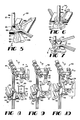
- the deboner 30 includes a support framework (not shown) with vertical sprocket shafts 36 rotatably supported in the framework.
- Sprockets 37 and 38 are mounted on the upper and lower ends of the sprocket shafts and upper and lower chains 32 and 33 extend about the upper and lower sprockets respectively.
- a motor 34 is connected in driving relationship with one sprocket and drives the sprocket and chain system in a counter clockwise direction as indicated by arrow 40.
- Deboning modules such as the single module 31 illustrated in Fig. 2, are carried around the deboner 30 in the counter clockwise direction 40 by the movement of the chains 32 and 33.
- Fig. 2 shows a deboning module 31 in detail, including a carrier assembly 49, a rotary bone holder assembly 50 and a stripper assembly 51.
- the carrier assembly 49 comprises a pair of vertical guide bars 42 extending between upper and lower chains 32 and 33.
- the rotary bone holder assembly 50 is fixedly mounted to an upper portion of the carrier assembly 49 while the stripper assembly 51 is slidably mounted upon the pair of vertical guide bars 42 of the carrier assembly.
- Each rotary bone holder assembly 50 includes a bone holder carrier block 81 which is rigidly mounted to upper chain 32.
- a bone holder block 82 is rigidly mounted to the bone holder carrier block 81. Near one end of the bone holder block 82 is mounted a bone holder sprocket 83.
- a vertical axle 84 extends through an opening (unshown) in the bone holder block 82.
- Vertical axle 84 is rigidly mounted at its lower end to the cylindrical support block 86 and is rigidly mounted at its upper end to the bone holder turning sprocket 83.
- a bone carrier 87 is rigidly attached to the cylindrical support block 86 and includes an upright stem 88 and a receiving yoke 89.
- Upright stem 88 is offset from the center of the cylindrical support block 86 such that the vertical axis 91 extends through yoke gap 92 in the receiving yoke 89.
- the receiving yoke 89 is bifurcated and is approximately U-shaped.
- each deboning module 31 revolves in a counter-clockwise direction about the deboner 30 in direction B
- the bone holder turning sprocket 83 of each module engages turning protrusions 93 in selected positions.
- Each turning protrusion 93 causes sprocket 83 to rotate 90 degrees as the sprocket moves past the protrusion.
- the protrusion 93 By selectively placing the protrusion 93 in the path of sprocket 83 on one side or the other of the vertical axis 91 about which the sprocket rotates, the sprocket is caused to rotate either in a clockwise direction or in a counter-clockwise direction as required.
- the turning sprocket 83 moves into engagement with a sprocket turning protrusion 93
- the sprocket rotates 90 degrees, which results in the rotary bone holder 87 rotating 90 degrees as well.
- Each deboning module 31 also includes a stripper assembly 51 movably mounted upon the vertical guide bars 42.
- each stripper assembly comprises a carrier block 60 that has a pair of vertical openings 61 mounted about vertical guide bars 42.
- a cam roller 62 is rotatably mounted to carrier block 60 and is received in a stripper module cam track 43.
- the cam roller 62 follows the cam track 43 to raise and lower the stripper assembly upon the guide bars 42.
- Stripper block 63 is rigidly mounted to and carried by carrier block 60.
- Blade support arms 67 and 68 each are rigidly mounted at their upper ends to stripper blades 65, 66, and each blade support arm is rigidly mounted at its lower end to a half gear 71, 72.
- Each half gear is pivoted about a pivot pin 73, 74 with the pivot pins 73, 74 being mounted to stripper block 63.
- the half gears 71, 72 have teeth 77, 78 which engage the opposite half gear 72, 71.
- Stripper block 63 is shaped so as to receive blade support arms 67 and 68 and half gears 71 and 72, with enough space being formed within the stripper block to accommodate the tilting movement of elements.
- Springs such as a pair of coil tension springs 79, are connected at their ends to carrier block 60 and the lower end of blade support arm 67 to urge the stripper blades 65 and 66 toward engagement with each other.
- a guard pin 76 is mounted above the teeth 77, 78 to prevent meat scraps and debris from fouling the gear teeth.
- Cam arm 69 is rigidly mounted at one end to first half gear 71 and extends beneath and beyond carrier block 60 and between vertical guide bars 42.
- Cam follower 70 is mounted on the other end of cam arm 69.
- first, second and third stripper blade cam tracks 44, 45 and 46 are positioned below stripper module cam track 43 for causing cam follower 70 to move vertically relative to carrier block 60 of the stripper assembly 51.
- the cams work to raise and lower the follower relative to the carrier block 60, which causes the stripper blades 65 and 66 to open and close.
- second cam 45 which works to close the stripper blades 65, 66, is pivotably mounted at one end and attached to a coil spring 47 at an opposite end. This arrangement allows the cam to operate with some amount of compliance when closing the blades.
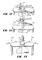
- stripper blades 65 and 66 have complementary shaped facing edges 95 and 96.
- Stripper blade 65 includes a central half opening or recess 97 while stripper blade 66 includes a similar half opening or recess 98, which, when moved together form a circular opening.
- Outer protrusions 100 and 101 of stripper blade 65 fit about inner protrusions 102 and 103 of stripper blade 66 when the blades move together. This tends to lock the blades in a precise fit when they move together about bone 105 of a poultry thigh 106, with the blades 65 and 66 being locked together above substantially all of the meat 107 of the poultry thigh.
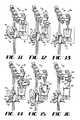
- Figs. 8-16 illustrate the functions of the deboning modules 31 as the modules progress through the processing path about the thigh deboner 30.
- Figs. 8-16 correspond to positions P1 through P9 as indicated on Fig. 1.
- a first and second pair of cutting stations 53 and 54 Located between positions P1 and P2 in Fig. 1 are a first and second pair of cutting stations 53 and 54.
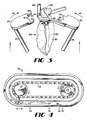
- a rotary disk cutting station indicated at 55 and meat transfer member indicated at 56 are located between positions P7 and P9.
- a bone ejection station indicated generally at 57 is located in the vicinity of position P9.
- first cutting station 53 is positioned in the path of travel of the bone carrier 87 as the bone carrier moves a thigh 106 in the direction as indicated by arrow B.
- Cutting station 53 includes a pair of cutting blades 111 and 112 that are spring urged toward the path of the poultry thigh 106.
- cutting blades 111 and 112 are located at an elevation just below the bone receiver yoke 89 of the bone carrier 87. With this arrangement, cutting blades 111 and 112 cut through the meat 107 and muscles of the poultry thigh 106 just below the upper knuckle 108 of the thigh bone 105.
- a second cutting station 54 includes a set of similar cutting blades 113 and 114 which are positioned just beyond cutting blades 111 and 112 in the path of the poultry thigh 106, and blades 113 and 114 are located just above the yoke 89 of bone carrier 87.
- bone carrier 87 and the poultry thigh 106 have rotated 90 degrees when moved from the position of Fig. 5 to the position of Fig. 6, so that the cutting blades 113 and 114 cut in the areas of the meat and muscles adjacent the upper end of the bone of the poultry thigh that was not previously cut by blades 111 and 112.
- Upright stem 88 has notches 85 in a lower portion adjacent bone carrier receiving yoke 89 to allow the cutting blades 113 and 114 to cut the meat while avoiding contact with the upright stem.
- a pair of strips 116 and 117 Positioned just below and extending beyond cutting blades 113 and 114 are a pair of strips 116 and 117 which are inclined downwardly for a short distance in the direction of travel indicated by arrow B of the thigh 106 and which tend to push the meat downwardly away from the upper knuckle 108 of the thigh bone 105 and make a space for the stripper blades 65 and 66 to reach the bone 105.
- each poultry thigh deboner 30 When the revolving poultry thigh deboner 30 (Fig. 1) is in operation, its motor 34 causes the upper and lower chains 32 and 33 to be driven by the upper and lower sprockets 37, 38 and causes the chains to rotate in the counter-clockwise direction as indicated by arrow 40.
- An operator retrieves poultry thighs from a supply and places each poultry thigh in a rotary bone holder 50 of each revolving deboning module 31.
- the poultry thigh is mounted in the bone holder 50 by inserting the upper knuckle 108 of the bone into the gap 92 of the bone receiving yoke 89, with the yoke supporting the upper knuckle 108 of the poultry thigh.
- each poultry thigh is firmly supported in and suspended beneath the bone carrier 87.
- each poultry thigh 106 is moved along a processing path through a series of processing positions indicated generally at P1 through P9 in Fig. 1. As illustrated in Figs. 1 and 8, as the deboning module 31 carrying a poultry thigh 106 moves into the position indicated at P1 the poultry thigh 106 is urged further into the yoke gap 92 of the bone carrier 87 by means of a pair of ramps 121 and 122. As the deboning module 31 moves through the first position indicated at P1 as shown in Fig.
- the U-shaped opening or gap 92 of the receiving yoke 89 is oriented away from the guide rods 42 in the general direction indicated by arrow A and the stripper assembly 51 is located in a lowered positioned with the stripper blades in a closed position.
- the cam roller 62 of the carrier block is forced upwardly in the direction of C by the cam track 43.
- first cam surface 44 urges the cam follower 70 protruding from beneath carrier block 60 downwardly thereby causing the first gear half 71 to rotate in a counter-clockwise direction.
- the teeth 77 on the gear 71 engage the teeth 78 on the second half gear 72 to cause half gear 72 to rotate the same amount in a clockwise direction. This causes the blade support arms 67 and 68 to open up, moving the stripper blades 65 and 66 apart from one another.
- Figs. 1 and 9 as the deboning module progresses from position P1 to position P2 the stripper blades 65 and 66 continue to open up while the entire stripper assembly 51 continues to move upwardly in the direction of C toward the rotary bone holder assembly 50. Between positions P1 and P2 the rotary holder engages a first cutting station 53, as seen in Fig. 5. A pair of stationary knife blades 111 and 112 cut the skin of the thigh 106 as the rotary bone holder progresses past the station 53 in the direction of B.
- the bone holder sprocket 83 engages a bone holder turning protrusion 93 which causes the sprocket to rotate in a counter-clockwise direction, leaving the bone carrier 87 oriented with the opening or gap 92 aligned with arrow B.
- the rotary bone holder assembly engages a second cutting station 54, as indicated in Figs. 1 and 6. Second cutting station 54 operates to cut the skin of the thigh 106 above the plane of the receiving yoke 89.
- the deboning module 31 engages another bone holder sprocket turning protrusion 93 which causes the bone holder sprocket 83 to rotate in a clockwise direction, leaving the receiving yoke 89 facing out in the direction of A.
- the poultry thigh 106 engages as pair of strips or ramps 116 and 117, which work to force or push the meat 107 of the thigh down and away from the receiving yoke 89, providing a space for the stripper blades to engage the poultry thigh 106. (See Fig. 7)
- the stripper assembly 51 continues to approach the rotary bone holder assembly 50.
- the first cam surface 44 begins to allow the cam follower 70 to close the stripper blades 65 and 66 in the directions indicated by arrows 118, 119 of Figs. 3 and 10. This action continues until the stripper assembly 51 reaches its zenith as indicated in position P4 of Fig. 11 At this juncture, the stripper blades 65 and 66 are closed upon the poultry thigh 106. As best seen in Fig. 17, the blades 65 and 66 will be substantially closed around the bone 105 of the poultry thigh 106, in a position just below the bone carrier 87.
- the second cam surface 45 urges the cam follower 70 upwardly, thereby working to close the stripper blades 65 and 66 about the poultry thigh 106 and to keep them closed.
- the compliance provided by spring 47 allows cam surface 45 to close the blades about the thigh while avoiding fragmenting the bone.
- the cam track 43 causes the stripper assembly 51 to descend in the direction indicated by arrows 99 by forcing the cam roller 62 downwardly. This downward motion causes the stripper blades 65 and 66 to begin to pull the meat 107 off of the thigh bone 105, exerting forces on the blades which tends to cause them to open.
- the spring 79 of Fig. 2 permits the stripping blades 65 and 66 to move away from each other slightly as indicated by the arrows 109 and 110, and then back toward each other, so that the downward movement of the stripping blades as indicated by arrows 99 is not impeded.
- the meat 107 of the thigh is substantially stripped from the thigh bone, with a small portion of meat and tissue extending from the lower knuckle to the stripper blades.
- a rotary disk cutting station indicated at 57 (See Fig. 1 and Fig. 14).
- a rotary disk cutting blade 123 is positioned in the path B of the poultry thigh at a level just beneath the lower knuckle 104 of the bone 105 and cuts any portion of the meat 107 that remains clinging to the bone 105. This completely separates the meat from the bone of the poultry thigh.
- the meat 107 is then permitted to drop onto a waiting collector, such as a belt conveyor, and the meat is transported away from the revolving poultry thigh deboner. Any meat which remains attached to the stripper blades 65 and 66 is then swept off of the stripper blades by meat sweeping member 124 as the deboning module moves past. (See Fig. 15). This is accomplished by opening up the stripper blades 65 and 66 by the action of the third cam surface 45, which allows the meat then to begin to fall and to be engaged by the meat sweeping member 124 which acts similar to a plow.
- the rotary bone holder is rotated one full revolution plus 90 degrees counter-clockwise, with the result that the yoke 89 of the rotary bone holder is facing in the direction of B when the rotary bone holder approaches positions P7 and P8.
- the bone holder sprocket 83 is once again turned 90 degrees clockwise to orient the receiving yoke 89 to be facing out in the direction of A as indicated in Fig. 16.
- a pair of stationary bone engagement rods 126 and 127 engage the poultry thigh bone 105 and remove it from the receiving yoke 89 of the bone carrier 87.
- the bones 105 can then be collected and transported away from the revolving poultry thigh deboner.
- the bones of poultry thighs are curved, and each thigh is supported in the rotary bone holder assembly 50 with their bones 105 in a substantially upright attitude.
- the bones are each rotated about their length as the stripper blades 65 and 66 engage the poultry thigh and move along the length of the bone. This combined scraping and turning action about the bone tends to effectively remove the meat from the bone even though the bone is curved.
Landscapes
- Life Sciences & Earth Sciences (AREA)
- Engineering & Computer Science (AREA)
- Wood Science & Technology (AREA)
- Zoology (AREA)
- Food Science & Technology (AREA)
- Processing Of Meat And Fish (AREA)
Applications Claiming Priority (2)
| Application Number | Priority Date | Filing Date | Title |
|---|---|---|---|
| US07/264,890 US4893378A (en) | 1988-10-31 | 1988-10-31 | Revoving poultry thigh deboner |
| US264890 | 1988-10-31 |
Publications (1)
| Publication Number | Publication Date |
|---|---|
| EP0366855A1 true EP0366855A1 (de) | 1990-05-09 |
Family
ID=23008060
Family Applications (1)
| Application Number | Title | Priority Date | Filing Date |
|---|---|---|---|
| EP89106257A Withdrawn EP0366855A1 (de) | 1988-10-31 | 1989-04-08 | Rotierende Vorrichtung zum Entfernen von Fleisch von Geflügelschenkeln |
Country Status (2)
| Country | Link |
|---|---|
| US (1) | US4893378A (de) |
| EP (1) | EP0366855A1 (de) |
Cited By (6)
| Publication number | Priority date | Publication date | Assignee | Title |
|---|---|---|---|---|
| NL9301238A (nl) * | 1992-07-30 | 1994-02-16 | Maekawa Seisakusho Kk | Werkwijze en inrichting voor het verwijderen van bot uit vlees. |
| WO1998047381A2 (de) | 1997-04-21 | 1998-10-29 | K & S Ingenieurgesellschaft Sondermaschinenbau Gbr Hermann Kischke Und Hermann Schrader | Haltevorrichtungen für fleischteile, ihre anordnung in einer zentrifuge und verfahren zum entbeinen von fleischteilen |
| EP0961351A2 (de) * | 1998-05-29 | 1999-12-01 | Delphi Technologies, Inc. | Verbinder für flexible-Schaltplatte |
| US7530888B2 (en) | 2001-11-05 | 2009-05-12 | Stork Pmt B.V. | Method and device for removing a bone from an extremity of a slaughter animal |
| EP3120706A4 (de) * | 2014-04-23 | 2017-03-22 | Mayekawa Mfg. Co., Ltd. | Vorrichtung und verfahren zum entbeinen von fleisch mit knochen |
| KR20190126168A (ko) * | 2018-02-14 | 2019-11-08 | 가부시끼가이샤 마에가와 세이사꾸쇼 | 뼈 있는 다리살의 골육 분리 장치 및 뼈 있는 다리살의 골육 분리 방법 |
Families Citing this family (31)
| Publication number | Priority date | Publication date | Assignee | Title |
|---|---|---|---|---|
| US5001812A (en) * | 1988-10-31 | 1991-03-26 | Hazenbroek Jacobus E | Revolving poultry thigh deboner |
| US4993113A (en) * | 1989-04-03 | 1991-02-19 | Hazenbroek Jacobus E | On-line thigh deboner |
| EP0442554B1 (de) * | 1990-01-30 | 1994-01-05 | Stork Pmt B.V. | Verfahren und Vorrichtung zum Ausführen eines genauen Schnittes nahe dem Kniegelenk eines Beines eines geschlachteten Tieres |
| US5228881A (en) * | 1991-04-03 | 1993-07-20 | Gordex Corporation | Poultry leg boning apparatus |
| US5090940A (en) * | 1991-04-16 | 1992-02-25 | Oscar Mayer Foods Corporation | Drummette deboner |
| US5176562A (en) * | 1991-04-26 | 1993-01-05 | Foodcraft Holdings, Inc. | Dark meat deboner with leg scraper |
| US5833527A (en) * | 1996-01-23 | 1998-11-10 | Systemate Holland, B.V. | Poultry breast filleting apparatus |
| US6383067B1 (en) | 1999-11-05 | 2002-05-07 | Fpm International | Device for deboning of poultry parts |
| US7261629B2 (en) * | 2004-01-28 | 2007-08-28 | Systemate Group, B.V. | Poultry wing separator and partial deboner |
| NL1030388C2 (nl) * | 2005-11-10 | 2007-05-16 | Systemate Group Bv | Ontbener. |
| NL2002992C2 (en) * | 2009-06-10 | 2010-12-13 | Foodmate B V | Method and apparatus for automatic meat processing. |
| US8157625B2 (en) | 2010-01-26 | 2012-04-17 | Foodmate Bv | Method and apparatus for collecting meat from an animal part |
| US8632380B2 (en) | 2010-01-26 | 2014-01-21 | Foodmate B.V. | Method and apparatus for removing a sleeve of meat from an animal part having bone with knuckles on each of its opposite ends |
| US8789684B2 (en) | 2010-04-19 | 2014-07-29 | Foodmate Bv | Rotatable article support for a conveyor |
| NL2004573C2 (en) | 2010-04-19 | 2011-10-20 | Foodmate B V | Turning block alignment. |
| US8757354B2 (en) | 2010-04-19 | 2014-06-24 | Foodmate Bv | Turning block alignment |
| NL2006075C2 (en) | 2011-01-26 | 2012-07-30 | Foodmate B V | Rotationally indexed article support for a conveyor system having an alignment station. |
| NL2004574C2 (en) | 2010-04-19 | 2011-10-20 | Foodmate B V | Rotatable article support for a conveyor. |
| US8727839B2 (en) | 2011-01-21 | 2014-05-20 | Foodmate Bv | Poultry wing cutter for narrow pitch poultry lines |
| US8267241B2 (en) | 2011-01-26 | 2012-09-18 | Foodmate Bv | Rotationally indexed article support for a conveyor system having an alignment station |
| US8882571B2 (en) | 2011-01-26 | 2014-11-11 | Foodmate Bv | Method of deboning animal thighs for separating and collecting meat therefrom and apparatus for performing the method |
| EP2667728B1 (de) | 2011-01-26 | 2015-07-29 | Foodmate B.V. | Verfahren zum entbeinen von tierschenkeln zur trennung und entnahme von fleisch daraus und vorrichtung zur durchführung des verfahrens |
| US8430728B2 (en) | 2011-02-14 | 2013-04-30 | Foodmate Bv | Special cut poultry wing cutter |
| NL2009033C2 (en) | 2012-06-19 | 2013-12-23 | Foodmate B V | Weighing method and apparatus. |
| NL2009717C2 (en) | 2012-10-29 | 2014-05-01 | Foodmate B V | Method of and system for automatically removing meat from an animal extremity. |
| US8808068B2 (en) | 2012-10-29 | 2014-08-19 | Foodmate Bv | Method of and system for automatically removing meat from an animal extremity |
| NL2009718C2 (en) | 2012-10-29 | 2014-05-01 | Foodmate B V | Method of mechanically removing skin from animal parts. |
| US9078453B2 (en) | 2013-11-01 | 2015-07-14 | Foodmate B.V. | Method and system for automatically deboning poultry breast caps containing meat and a skeletal structure to obtain breast fillets therefrom |
| US8961274B1 (en) | 2013-12-18 | 2015-02-24 | Foodmate Bv | Selective tendon cutter and method |
| SE538388C2 (sv) * | 2014-02-06 | 2016-06-07 | Castema Innovations Ab | En nervbensborttagningsapparat för att ta bort nervben frånen fiskkropp |
| NL2027999B1 (en) * | 2021-04-16 | 2022-10-31 | Meyn Food Processing Tech Bv | Deboner for poultry parts |
Citations (10)
| Publication number | Priority date | Publication date | Assignee | Title |
|---|---|---|---|---|
| US3261054A (en) * | 1964-03-19 | 1966-07-19 | Campbell Soup Co | Automatic leg boning machine and system |
| US3581337A (en) * | 1969-08-28 | 1971-06-01 | Hormel & Co Geo A | Apparatus handling system for use in a deboning operation |
| US3672000A (en) * | 1970-08-31 | 1972-06-27 | Victor F Weaver Inc | Machine to de-bone chicken thighs |
| US4041572A (en) * | 1976-09-27 | 1977-08-16 | Victor F. Weaver, Inc. | Anatomical section de-boning machine |
| US4216565A (en) * | 1979-02-26 | 1980-08-12 | Anthony J. Volk | Meat stripping machine for fowl |
| US4327463A (en) * | 1980-10-10 | 1982-05-04 | Victor F. Weaver, Inc. | Single station anatomical section de-boning machine |
| GB2124883A (en) * | 1982-08-06 | 1984-02-29 | Mayer Oskar Foods | Apparatus for removing meat from poultry drumsticks |
| WO1985002320A1 (en) * | 1983-11-28 | 1985-06-06 | Commonwealth Scientific And Industrial Research Or | Method of and means for stripping meat from bones |
| US4639974A (en) * | 1985-07-02 | 1987-02-03 | Cagle's Inc. | Thigh deboner |
| EP0270513A1 (de) * | 1986-12-05 | 1988-06-08 | David Geoffrey Bowen | Vorrichtung zum Ausbeinen von Geflügel |
Family Cites Families (18)
| Publication number | Priority date | Publication date | Assignee | Title |
|---|---|---|---|---|
| US2897536A (en) * | 1958-04-04 | 1959-08-04 | Campbell Soup Co | Poultry boning machine |
| US3296653A (en) * | 1963-09-03 | 1967-01-10 | Asa B Segur | Apparatus for use in removing meat from poultry wings |
| US3348261A (en) * | 1963-11-20 | 1967-10-24 | Asa B Segur | Method for removing meat from poultry legs |
| US3456284A (en) * | 1966-10-10 | 1969-07-22 | Werner Machinery Co | Meat deboner machine |
| US3402423A (en) * | 1967-08-14 | 1968-09-24 | Hormel & Co Geo A | Apparatus for deboning meat |
| US3533128A (en) * | 1968-01-22 | 1970-10-13 | Hormel & Co Geo A | Apparatus for deboning meat |
| US3866271A (en) * | 1971-10-26 | 1975-02-18 | Prince Corp | Bone holding mechanism |
| US3965535A (en) * | 1974-10-17 | 1976-06-29 | Jo-Bi Farms, Inc. | Poultry leg boning machine |
| US4068350A (en) * | 1975-06-30 | 1978-01-17 | Prince Corporation | Article contour follower mechanism |
| US4213229A (en) * | 1978-05-25 | 1980-07-22 | Campbell Soup Company | Mechanical deboning of poultry |
| ATE14968T1 (de) * | 1980-10-01 | 1985-09-15 | Matthews Bernard Ltd | Verfahren und vorrichtung zum entfleischen der glieder von gefluegel. |
| US4402112A (en) * | 1981-04-02 | 1983-09-06 | Gasbarro Geno N | Automatic poultry deboning apparatus |
| US4377884A (en) * | 1981-07-29 | 1983-03-29 | Viscolosi Louis A | Apparatus for deboning poultry legs |
| AU556369B2 (en) * | 1982-02-08 | 1986-10-30 | Langen Research B.V. | Boning device |
| US4495675A (en) * | 1982-04-12 | 1985-01-29 | Hill Carl J | Method and apparatus for removing meat from the knuckled end of a bone |
| US4446600A (en) * | 1982-05-17 | 1984-05-08 | Hooley Eldon R | Machine for stripping meat from fowl leg and thigh bones |
| NL186429C (nl) * | 1983-11-29 | 1990-12-03 | Maekawa Seisakusho Kk | Inrichting voor het verwijderen van vlees van gewrichten omvattende benen van gevogelte. |
| NL8501363A (nl) * | 1985-05-13 | 1986-12-01 | Systemate Bv | Inrichting voor het ontbenen van dierbotten, zoals dijen van geslachte kippen. |
-
1988
- 1988-10-31 US US07/264,890 patent/US4893378A/en not_active Expired - Fee Related
-
1989
- 1989-04-08 EP EP89106257A patent/EP0366855A1/de not_active Withdrawn
Patent Citations (10)
| Publication number | Priority date | Publication date | Assignee | Title |
|---|---|---|---|---|
| US3261054A (en) * | 1964-03-19 | 1966-07-19 | Campbell Soup Co | Automatic leg boning machine and system |
| US3581337A (en) * | 1969-08-28 | 1971-06-01 | Hormel & Co Geo A | Apparatus handling system for use in a deboning operation |
| US3672000A (en) * | 1970-08-31 | 1972-06-27 | Victor F Weaver Inc | Machine to de-bone chicken thighs |
| US4041572A (en) * | 1976-09-27 | 1977-08-16 | Victor F. Weaver, Inc. | Anatomical section de-boning machine |
| US4216565A (en) * | 1979-02-26 | 1980-08-12 | Anthony J. Volk | Meat stripping machine for fowl |
| US4327463A (en) * | 1980-10-10 | 1982-05-04 | Victor F. Weaver, Inc. | Single station anatomical section de-boning machine |
| GB2124883A (en) * | 1982-08-06 | 1984-02-29 | Mayer Oskar Foods | Apparatus for removing meat from poultry drumsticks |
| WO1985002320A1 (en) * | 1983-11-28 | 1985-06-06 | Commonwealth Scientific And Industrial Research Or | Method of and means for stripping meat from bones |
| US4639974A (en) * | 1985-07-02 | 1987-02-03 | Cagle's Inc. | Thigh deboner |
| EP0270513A1 (de) * | 1986-12-05 | 1988-06-08 | David Geoffrey Bowen | Vorrichtung zum Ausbeinen von Geflügel |
Cited By (11)
| Publication number | Priority date | Publication date | Assignee | Title |
|---|---|---|---|---|
| NL9301238A (nl) * | 1992-07-30 | 1994-02-16 | Maekawa Seisakusho Kk | Werkwijze en inrichting voor het verwijderen van bot uit vlees. |
| WO1998047381A2 (de) | 1997-04-21 | 1998-10-29 | K & S Ingenieurgesellschaft Sondermaschinenbau Gbr Hermann Kischke Und Hermann Schrader | Haltevorrichtungen für fleischteile, ihre anordnung in einer zentrifuge und verfahren zum entbeinen von fleischteilen |
| EP0961351A2 (de) * | 1998-05-29 | 1999-12-01 | Delphi Technologies, Inc. | Verbinder für flexible-Schaltplatte |
| EP0961351A3 (de) * | 1998-05-29 | 2000-01-19 | Delphi Technologies, Inc. | Verbinder für flexible-Schaltplatte |
| US7530888B2 (en) | 2001-11-05 | 2009-05-12 | Stork Pmt B.V. | Method and device for removing a bone from an extremity of a slaughter animal |
| EP3120706A4 (de) * | 2014-04-23 | 2017-03-22 | Mayekawa Mfg. Co., Ltd. | Vorrichtung und verfahren zum entbeinen von fleisch mit knochen |
| AU2015251705B2 (en) * | 2014-04-23 | 2018-01-04 | Mayekawa Mfg. Co., Ltd. | Device and method for deboning meat with bone |
| RU2656394C2 (ru) * | 2014-04-23 | 2018-06-05 | Майекава Мфг. Ко., Лтд. | Устройство и способ для удаления костей из мяса с костями |
| KR20190126168A (ko) * | 2018-02-14 | 2019-11-08 | 가부시끼가이샤 마에가와 세이사꾸쇼 | 뼈 있는 다리살의 골육 분리 장치 및 뼈 있는 다리살의 골육 분리 방법 |
| EP3603405A4 (de) * | 2018-02-14 | 2020-06-24 | Mayekawa Mfg. Co., Ltd. | Fleischentbeinungsvorrichtung für nichtentbeintes fleisch und fleischentbeinungsverfahren für nichtentbeintes fleisch |
| US10993447B2 (en) | 2018-02-14 | 2021-05-04 | Mayekawa Mfg. Co., Ltd. | Bone-meat separation device for bone-in limb meat and bone-meat separation method for bone-in limb meat |
Also Published As
| Publication number | Publication date |
|---|---|
| US4893378A (en) | 1990-01-16 |
Similar Documents
| Publication | Publication Date | Title |
|---|---|---|
| US5067927A (en) | Revolving poultry thigh deboner | |
| EP0366855A1 (de) | Rotierende Vorrichtung zum Entfernen von Fleisch von Geflügelschenkeln | |
| EP0439784B1 (de) | Rotierende Vorrichtung zum Entfernen von Fleisch von Geflügelschenkeln | |
| US4993113A (en) | On-line thigh deboner | |
| AU618621B2 (en) | Revolving poultry thigh deboner | |
| US4769872A (en) | Poultry carcass and wings processor | |
| US5173076A (en) | Thigh deboner with tray conveyor | |
| EP0786206B1 (de) | Vorrichtung zum Entfernen von Fleisch von Geflügelschenkeln | |
| US4567624A (en) | Device for removing pieces of meat from breast of slaughtered poultry | |
| EP1346639B1 (de) | Verfahren zum Filetieren von Schlachtgefügel | |
| US4597136A (en) | On-line wing removal system | |
| US5462477A (en) | Method and device for deboning leg pieces of slaughtered animals | |
| US4377884A (en) | Apparatus for deboning poultry legs | |
| US5697837A (en) | Poultry breast filleting apparatus | |
| EP0442554B1 (de) | Verfahren und Vorrichtung zum Ausführen eines genauen Schnittes nahe dem Kniegelenk eines Beines eines geschlachteten Tieres | |
| US6024636A (en) | Expandable poultry deboner having a pre-cut installation | |
| US6027404A (en) | Poultry thigh deboner with movable stripper | |
| DK2724618T3 (en) | Method and system for automatic removal of meat from dyreekstremitet | |
| EP0552421A1 (de) | Verfahren und Vorrichtung zum kontinuierlichen Abtrennen der Beine von Schlachtgeflügel | |
| WO1993005660A1 (en) | Method and apparatus for separating the legs from the back of a poultry carcass | |
| US5176562A (en) | Dark meat deboner with leg scraper | |
| US8808068B2 (en) | Method of and system for automatically removing meat from an animal extremity | |
| EP1097643B1 (de) | Vorrichtung zum Entbeinen von Tiergliedern | |
| US8157625B2 (en) | Method and apparatus for collecting meat from an animal part | |
| US5102369A (en) | Dark meat deboner |
Legal Events
| Date | Code | Title | Description |
|---|---|---|---|
| PUAI | Public reference made under article 153(3) epc to a published international application that has entered the european phase |
Free format text: ORIGINAL CODE: 0009012 |
|
| AK | Designated contracting states |
Kind code of ref document: A1 Designated state(s): AT BE CH DE ES FR GB GR IT LI LU NL SE |
|
| 17P | Request for examination filed |
Effective date: 19901026 |
|
| 17Q | First examination report despatched |
Effective date: 19920224 |
|
| STAA | Information on the status of an ep patent application or granted ep patent |
Free format text: STATUS: THE APPLICATION IS DEEMED TO BE WITHDRAWN |
|
| 18D | Application deemed to be withdrawn |
Effective date: 19940309 |