EP0366165A2 - Bild-Bewegungsmessung - Google Patents
Bild-Bewegungsmessung Download PDFInfo
- Publication number
- EP0366165A2 EP0366165A2 EP19890202208 EP89202208A EP0366165A2 EP 0366165 A2 EP0366165 A2 EP 0366165A2 EP 19890202208 EP19890202208 EP 19890202208 EP 89202208 A EP89202208 A EP 89202208A EP 0366165 A2 EP0366165 A2 EP 0366165A2
- Authority
- EP
- European Patent Office
- Prior art keywords
- sample point
- maximum
- sample
- correlation
- point
- Prior art date
- Legal status (The legal status is an assumption and is not a legal conclusion. Google has not performed a legal analysis and makes no representation as to the accuracy of the status listed.)
- Granted
Links
Images

Classifications
-
- H—ELECTRICITY
- H04—ELECTRIC COMMUNICATION TECHNIQUE
- H04N—PICTORIAL COMMUNICATION, e.g. TELEVISION
- H04N19/00—Methods or arrangements for coding, decoding, compressing or decompressing digital video signals
- H04N19/50—Methods or arrangements for coding, decoding, compressing or decompressing digital video signals using predictive coding
- H04N19/503—Methods or arrangements for coding, decoding, compressing or decompressing digital video signals using predictive coding involving temporal prediction
- H04N19/51—Motion estimation or motion compensation
- H04N19/523—Motion estimation or motion compensation with sub-pixel accuracy
-
- G—PHYSICS
- G06—COMPUTING OR CALCULATING; COUNTING
- G06T—IMAGE DATA PROCESSING OR GENERATION, IN GENERAL
- G06T7/00—Image analysis
- G06T7/20—Analysis of motion
- G06T7/262—Analysis of motion using transform domain methods, e.g. Fourier domain methods
-
- H—ELECTRICITY
- H04—ELECTRIC COMMUNICATION TECHNIQUE
- H04N—PICTORIAL COMMUNICATION, e.g. TELEVISION
- H04N5/00—Details of television systems
- H04N5/14—Picture signal circuitry for video frequency region
- H04N5/144—Movement detection
- H04N5/145—Movement estimation
Definitions
- the present invention relates to a method of picture motion measurement comprising correlating two pictures to determine correlation as a function of displacement thereby to determine one or more peak correlation values corresponding to respective motion vectors.
- the invention also relates to apparatus for use with the above method.
- the invention according to a first aspect provides a method of picture motion measurement comprising correlating two pictures to determine correlation as a function of displacement thereby to determine one or more peak correlation values corresponding to respective motion vectors, said method being characterised by the steps of:-
- the invention may be further characterised in that the sample points may be spaced one pixel apart, and that if said difference d2 or proportional quantity is greater than one half of the difference d1 or proportional quantity the said peak correlation value may be assumed to be coincident with the sample point of maximum correlation value whilst if the difference d2 or proportional quantity is less than the difference d1 or proportional quantity the peak correlation value may be assumed to be located on the said line halfway between the sample point of maximum correlation value and the third sample point. This gives the preferred sub-pixel accuracy.
- the two pictures may be adjacent frames from the television signal with each frame being subdivided into a plurality of regions, correlation taking place between corresponding regions of the adjacent frames.
- Apparatus for picture motion measurement may be characterised in that it comprises means for providing from two pictures a sampled correlation function for determining correlation as a function of displacement which correlation surface contains at least one sample point of maximum correlation value, means for locating said sample point of maximum correlation value, means for examining sample points in said correlation function immediately surrounding said maximum sample point and for determining a second sample point which is associated with the steepest gradient between said surrounding and said maximum value sample points, means for determining the difference (d1) in magnitude between that of the maximum sample point and that of said second sample point or other quantity proportional thereto, means for determining the difference (d2) in magnitude between that of said maximum sample point and that of a third of said surrounding sample points which is colinear with said maximum and said second sample points but remote from said second sample point or other quantity proportional thereto, and means for comparing the two results so produced to determine the location of the peak correlation function in said correlation surface associated with said maximum sample point to an accuracy better than the interval between
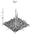
- Figure 1 shows a correlation surface obtained by correlating the same region in two adjacent television frames. It is assumed that each region is 32 pixels x 32 lines and thus the displacement in the X and Y directions of Figure 1 run from -16 to +16 sample positions with each sample being one pixel apart. In practice Figure 1 would not appear as a continuous correlation surface but as a series of discrete samples of given magnitudes spaced one pixel apart.
- the correlation surface may be achieved by means of phase correlation as described in the above U.K. Patent Application or in the article "Video-rate Image Correlation Processor" by J. J. Pearson, D. C. Hines Jr., S. Golosman and C. D. Kuglin, SPIE Vol.
- Zero displacement represents lack of movement and the peaks located away from the zero displacement position indicate varying degrees of movement of components within the region.
- the samples are provided at intervals of one pixel apart it is preferable if the positions of the actual peaks can be determined to sub-pixel accuracy. How this can be achieved is described in relation to Figure 2.
- the correlation surface actually produces a series of discrete samples at points one pixel apart. Thus a peak may not coincide with a localised sample of greatest magnitude.
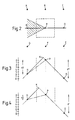
- the correlation surface is first of all examined to determine a point with the sample of greatest magnitude. This is shown in Figure 2 as the point P which figure is a plan view of a portion of the correlation surface. Having found sample point P the eight sample points A to H one pixel apart surrounding point P are considered and the relative gradients of lines joining point P with each of the surrounding points A to H are found. The surrounding point through which the line of steepest gradient passes is selected and its magnitude established. It is assumed that this sample point is point D.
- the peak associated with the sample P must be located within the cross-hatched triangle having its apex at point P and additionally within the broken line square where respective sides are located at a distance of a half pixel interval from points B, D, F and H.
- Two locations for the actual peak are illustrated in Figures 3 and 4 which are sectional views of the part of the correlation surface taken along a plane passing through sample points H, P and D.
- the peak K is located closer to the coordinates of the sample point P whilst in Figure 4 peak K is located closer to the coordinates of the half pixel interval than to that of sample point P.
- the difference d1 in magnitude between that of the sample at point P and that of the sample at point D is then determined.
- Figure 5 shows a block diagram of apparatus for performing the method described above. Such apparatus would in general be located with the signal processing equipment at the transmission side in the case of television signals but it is also possible, though less economic, for such apparatus to be located in television receiving apparatus.
- the reference 1 indicates an input terminal to which a luminance signal is applied either frame by frame or region by region.
- This luminance signal is applied to a picture memory 2 in which the luminance signal is delayed by a frame period which delayed luminance output is applied to a processing stage 3 where it is subjected to a two dimensional Fourier transform.
- the luminance signal at input terminal 1 is also applied directly to a second processing stage 4 in which the undelayed luminance is similarly subjected to a two dimensional Fourier transform.
- phase subtractor 5 which establishes the difference in phase between its two inputs and applies this to a third processing stage 6 whose output is the inverse Fourier transform.
- This output is the correlation function as illustrated by the typical correlation surface as shown in Figure 1 though in discrete correlation sample form as described above in relation to that figure.
- the correlation samples from processor stage 6 are applied to a largest samples locator 7 which provides the location or locations for one or more sample points having a magnitude above a certain value. These locations are applied to a peak locator 8 which looks for samples of maximum magnitude associated with different peaks.
- One such sample may be that represented by P in Figure 2.
- the location of the sample P under investigation is applied to a steepest gradient locator 9 together with the correlation samples from processor stage 6 and each of the eight samples surrounding that at point P are examined to determine which of the gradients from these sample points to point P is the steepest. As in the case of Figure 2 it will be assumed that this steepest gradient passes through sample point D and the output of steepest gradient selector 9 will identify this point and the difference (d1) in magnitude between the samples at points P and D.
- the output of the peak locator 8 and the correlation samples from processor stage 6 are also applied to an opposite sample point selector 10 which also receives the identity of the sample point selected by the steepest gradient locator 9.
- the selector 19 selects the sample point colinear with points P and D but remote from point D (in the case of Figure 2 this is sample point H) and provides at its output the difference (d2) in magnitude between the samples at points P and H.
- This together with the similar information regarding difference d1 is applied to a magnitude ratio counter 11 which makes the comparisons described above to determine whether difference d2 is greater or less than 0.5 d1.
- the results of this comparison which is an indication of the real peak position is applied to a high resolution vector calculator 12 which also receives the location of the sample P under investigation from peak locator 8.
- Calculator 12 calculates to sub-pixel accuracy the motion vector for the peak associated with sample point P from the information supplied, the higher resolution motion vector being present at an output 13. The process is repeated for other peaks in the picture or region.
- the opposite sample point detector 10 and the magnitude ratio counter 11 may be replaced respectively by an opposite gradient locator and a gradient ratio calculator.
- the opposite gradient locator will then determine the gradient between the opposite sample point H and the maximum sample point P and the gradient ratio calculator will then compare the gradient for the points H-P with that for the points D-P which will be derived from the steepest gradient locator 9. If the gradient for points H-P is greater than half gradient for points D-P then the actual peak will be located closer to sample point P than to the half pixel point. However if the gradient for points H-P is less than half the gradient for points D-P then the actual peak will be located closer to the half pixel point than to the sample point P. This can be seen from the chain link lines in Figures 3 and 4. It will be appreciated that these respective gradients are proportional to the magnitude differences d1 and d2.
Landscapes
- Engineering & Computer Science (AREA)
- Multimedia (AREA)
- Signal Processing (AREA)
- Physics & Mathematics (AREA)
- Mathematical Physics (AREA)
- Computer Vision & Pattern Recognition (AREA)
- General Physics & Mathematics (AREA)
- Theoretical Computer Science (AREA)
- Image Analysis (AREA)
- Compression Or Coding Systems Of Tv Signals (AREA)
- Testing, Inspecting, Measuring Of Stereoscopic Televisions And Televisions (AREA)
- Television Systems (AREA)
Applications Claiming Priority (2)
| Application Number | Priority Date | Filing Date | Title |
|---|---|---|---|
| GB8820837A GB2222498A (en) | 1988-09-05 | 1988-09-05 | Picture motion measurement |
| GB8820837 | 1988-09-05 |
Publications (3)
| Publication Number | Publication Date |
|---|---|
| EP0366165A2 true EP0366165A2 (de) | 1990-05-02 |
| EP0366165A3 EP0366165A3 (de) | 1991-09-11 |
| EP0366165B1 EP0366165B1 (de) | 1995-05-17 |
Family
ID=10643109
Family Applications (1)
| Application Number | Title | Priority Date | Filing Date |
|---|---|---|---|
| EP89202208A Expired - Lifetime EP0366165B1 (de) | 1988-09-05 | 1989-09-01 | Bild-Bewegungsmessung |
Country Status (5)
| Country | Link |
|---|---|
| US (1) | US5008744A (de) |
| EP (1) | EP0366165B1 (de) |
| JP (1) | JP2947361B2 (de) |
| DE (1) | DE68922689T2 (de) |
| GB (1) | GB2222498A (de) |
Cited By (4)
| Publication number | Priority date | Publication date | Assignee | Title |
|---|---|---|---|---|
| EP0765088A3 (de) * | 1995-09-22 | 1998-12-02 | Tektronix, Inc. | Videosignalbewegungsschätzung mit fraktionierten Pixeln |
| EP0999521A3 (de) * | 1998-11-05 | 2002-01-02 | Tektronix, Inc. | Hochgenaue räumliche Unterpixelausrichtung von numerischen Bildern |
| EP2146509A1 (de) * | 2008-07-15 | 2010-01-20 | Sony Corporation | Bewegungsvektorerkennung |
| EP2146510A1 (de) * | 2008-07-15 | 2010-01-20 | Sony Corporation | Bewegungsvektorerkennung |
Families Citing this family (3)
| Publication number | Priority date | Publication date | Assignee | Title |
|---|---|---|---|---|
| GB2277000B (en) * | 1993-04-08 | 1997-12-24 | Sony Uk Ltd | Motion compensated video signal processing |
| GB2278972B (en) * | 1993-06-09 | 1997-06-04 | Sony Uk Ltd | Motion vector generation |
| US6240208B1 (en) * | 1998-07-23 | 2001-05-29 | Cognex Corporation | Method for automatic visual identification of a reference site in an image |
Family Cites Families (6)
| Publication number | Priority date | Publication date | Assignee | Title |
|---|---|---|---|---|
| KR930006866B1 (ko) * | 1984-09-07 | 1993-07-24 | 쏘니 가부시기가이샤 | 텔레비젼신호의 움직임검출회로 |
| JPS61113377A (ja) * | 1984-11-07 | 1986-05-31 | Sony Corp | テレビジヨン信号の動き検出装置 |
| GB8604253D0 (en) * | 1986-02-20 | 1986-03-26 | British Broadcasting Corp | Video signal processing systems |
| EP0261137B1 (de) * | 1986-03-19 | 1991-10-16 | British Broadcasting Corporation | Fernsehbild-bewegungsmessung |
| FR2624682B2 (fr) * | 1987-03-23 | 1990-03-30 | Thomson Csf | Procede et dispositif d'estimation de mouvement dans une sequence d'images animees |
| EP0294962B1 (de) * | 1987-06-09 | 1995-07-19 | Sony Corporation | Bewertung von Bewegungsvektoren in Fernsehbildern |
-
1988
- 1988-09-05 GB GB8820837A patent/GB2222498A/en not_active Withdrawn
-
1989
- 1989-08-02 US US07/388,421 patent/US5008744A/en not_active Expired - Fee Related
- 1989-09-01 DE DE68922689T patent/DE68922689T2/de not_active Expired - Fee Related
- 1989-09-01 EP EP89202208A patent/EP0366165B1/de not_active Expired - Lifetime
- 1989-09-04 JP JP1227643A patent/JP2947361B2/ja not_active Expired - Lifetime
Cited By (8)
| Publication number | Priority date | Publication date | Assignee | Title |
|---|---|---|---|---|
| EP0765088A3 (de) * | 1995-09-22 | 1998-12-02 | Tektronix, Inc. | Videosignalbewegungsschätzung mit fraktionierten Pixeln |
| EP0999521A3 (de) * | 1998-11-05 | 2002-01-02 | Tektronix, Inc. | Hochgenaue räumliche Unterpixelausrichtung von numerischen Bildern |
| US6483538B2 (en) | 1998-11-05 | 2002-11-19 | Tektronix, Inc. | High precision sub-pixel spatial alignment of digital images |
| EP2146509A1 (de) * | 2008-07-15 | 2010-01-20 | Sony Corporation | Bewegungsvektorerkennung |
| EP2146510A1 (de) * | 2008-07-15 | 2010-01-20 | Sony Corporation | Bewegungsvektorerkennung |
| CN101631244B (zh) * | 2008-07-15 | 2012-07-04 | 索尼株式会社 | 运动矢量检测设备和方法、图像编码设备和程序 |
| US8358860B2 (en) | 2008-07-15 | 2013-01-22 | Sony Corporation | Motion vector detecting device, motion vector detecting method, image encoding device, and program |
| US8385423B2 (en) | 2008-07-15 | 2013-02-26 | Sony Corporation | Motion vector detecting device, motion vector detecting method, image encoding device, and program |
Also Published As
| Publication number | Publication date |
|---|---|
| JP2947361B2 (ja) | 1999-09-13 |
| GB8820837D0 (en) | 1988-10-05 |
| US5008744A (en) | 1991-04-16 |
| JPH02108394A (ja) | 1990-04-20 |
| DE68922689T2 (de) | 1995-11-16 |
| DE68922689D1 (de) | 1995-06-22 |
| EP0366165A3 (de) | 1991-09-11 |
| EP0366165B1 (de) | 1995-05-17 |
| GB2222498A (en) | 1990-03-07 |
Similar Documents
| Publication | Publication Date | Title |
|---|---|---|
| US5311305A (en) | Technique for edge/corner detection/tracking in image frames | |
| US6532264B1 (en) | Processing sequential video images to detect image motion among interlaced video fields or progressive video images | |
| DE69230115T2 (de) | Auswertungsvorrichtung und Methode verwendbar für ein Gerät zur Detektion von Bewegungsvektoren | |
| CN1134077A (zh) | 确定特征点的方法与设备 | |
| JPH07505749A (ja) | ディジタルビデオ信号の画像シーケンスにおける不所望の全体的画像不安定性の推定方法 | |
| Naoya | Optical flow detection by color images | |
| US4974084A (en) | Method and apparatus for picture motion measurement | |
| US4985765A (en) | Method and apparatus for picture motion measurement whereby two pictures are correlated as a function of selective displacement | |
| US5008744A (en) | Method and apparatus for picture motion measurement using picture correlation as a function of displacement | |
| EP0454481A2 (de) | Vorrichtung zur Detektion von Bewegungsvektor | |
| Morimoto et al. | Automated analysis of 3-D shape and surface strain distributions of a moving object using stereo vision | |
| Vlachos | Simple method for estimation of global motion parameters using sparse translational motion vector fields | |
| JP2000171214A (ja) | 対応点検索方法及びこれを利用した三次元位置計測方法 | |
| US5144373A (en) | Detection of range discontinuities in stereoscopic imagery | |
| EP0565948B1 (de) | Verfahren und Schaltung zur Verdoppelung der vertikalen und horizontalen Auflösung eines auf einem Bildschirm dargestellten Bildes | |
| JP3074292B2 (ja) | テンプレートマッチング処理方法 | |
| JP2741888B2 (ja) | 階層的画像マッチング処理方法および装置 | |
| EP0648359B1 (de) | Korelationssignalverarbeitung. | |
| Beghdadi et al. | A fast incremental approach for accurate measurement of the displacement field | |
| EP0639926A1 (de) | Verfahren und Vorrichtung zur Bewegungsvektorschätzung mit Blockübereinstimmung | |
| JPH02118888A (ja) | 画像の動きベクトル検出装置 | |
| GB2266639A (en) | Motion estimation. | |
| Kao | A parallel Triangle Operator for Noise Removal in true colour images | |
| JPH01128170A (ja) | 画像の平滑化処理方法 | |
| Hemmendorff et al. | Phase-based Image Motion Estimation and Registration: Phoenix, AZ, USA |
Legal Events
| Date | Code | Title | Description |
|---|---|---|---|
| PUAI | Public reference made under article 153(3) epc to a published international application that has entered the european phase |
Free format text: ORIGINAL CODE: 0009012 |
|
| AK | Designated contracting states |
Kind code of ref document: A2 Designated state(s): DE FR GB IT |
|
| PUAL | Search report despatched |
Free format text: ORIGINAL CODE: 0009013 |
|
| AK | Designated contracting states |
Kind code of ref document: A3 Designated state(s): DE FR GB IT |
|
| RAP3 | Party data changed (applicant data changed or rights of an application transferred) |
Owner name: N.V. PHILIPS' GLOEILAMPENFABRIEKEN Owner name: PHILIPS ELECTRONICS UK LIMITED |
|
| 17P | Request for examination filed |
Effective date: 19920311 |
|
| 17Q | First examination report despatched |
Effective date: 19931102 |
|
| GRAA | (expected) grant |
Free format text: ORIGINAL CODE: 0009210 |
|
| AK | Designated contracting states |
Kind code of ref document: B1 Designated state(s): DE FR GB IT |
|
| REF | Corresponds to: |
Ref document number: 68922689 Country of ref document: DE Date of ref document: 19950622 |
|
| ITF | It: translation for a ep patent filed | ||
| ET | Fr: translation filed | ||
| PLBE | No opposition filed within time limit |
Free format text: ORIGINAL CODE: 0009261 |
|
| STAA | Information on the status of an ep patent application or granted ep patent |
Free format text: STATUS: NO OPPOSITION FILED WITHIN TIME LIMIT |
|
| 26N | No opposition filed | ||
| REG | Reference to a national code |
Ref country code: FR Ref legal event code: CD |
|
| PGFP | Annual fee paid to national office [announced via postgrant information from national office to epo] |
Ref country code: GB Payment date: 19990923 Year of fee payment: 11 |
|
| PGFP | Annual fee paid to national office [announced via postgrant information from national office to epo] |
Ref country code: DE Payment date: 19991110 Year of fee payment: 11 |
|
| PG25 | Lapsed in a contracting state [announced via postgrant information from national office to epo] |
Ref country code: GB Free format text: LAPSE BECAUSE OF NON-PAYMENT OF DUE FEES Effective date: 20000901 |
|
| PGFP | Annual fee paid to national office [announced via postgrant information from national office to epo] |
Ref country code: FR Payment date: 20000925 Year of fee payment: 12 |
|
| GBPC | Gb: european patent ceased through non-payment of renewal fee |
Effective date: 20000901 |
|
| PG25 | Lapsed in a contracting state [announced via postgrant information from national office to epo] |
Ref country code: DE Free format text: LAPSE BECAUSE OF NON-PAYMENT OF DUE FEES Effective date: 20010601 |
|
| PG25 | Lapsed in a contracting state [announced via postgrant information from national office to epo] |
Ref country code: FR Free format text: LAPSE BECAUSE OF NON-PAYMENT OF DUE FEES Effective date: 20020531 |
|
| REG | Reference to a national code |
Ref country code: FR Ref legal event code: ST |
|
| PG25 | Lapsed in a contracting state [announced via postgrant information from national office to epo] |
Ref country code: IT Free format text: LAPSE BECAUSE OF NON-PAYMENT OF DUE FEES;WARNING: LAPSES OF ITALIAN PATENTS WITH EFFECTIVE DATE BEFORE 2007 MAY HAVE OCCURRED AT ANY TIME BEFORE 2007. THE CORRECT EFFECTIVE DATE MAY BE DIFFERENT FROM THE ONE RECORDED. Effective date: 20050901 |